
Main Components of a Marine Oil Purifier
What does each purifier component do, and how do the parts work together?
Key Principles at a Glance 8 points
- The purifier is a system rather than a single part: frame, bowl assembly, drive, feed and outlet arrangements, operating-water system and control panel must all work together.
- The bowl assembly is the separating element — bowl body and hood enclose the disc stack, distributor, top disc and sliding bowl bottom.
- The distributor accelerates the feed up to bowl speed and delivers it to the outer edge of the disc stack, where separation begins.
- The gravity disc sets the position of the oil-water interface, and therefore decides which outlet each liquid phase leaves by.
- The sliding bowl bottom (main cylinder) is moved by operating water, and the pilot valve plus operating-water passages control when the bowl opens and closes.
- The light-liquid and heavy-liquid outlet impellers pump the separated phases out against back pressure, so outlet pressure affects interface position.
- Sealing rings and O-rings keep oil, water and operating water in their correct passages; a failed ring changes the pressures and destroys the interface.
- Component-level troubleshooting works because each symptom points to the part whose function is missing.
1. Learning objectives
Course position: Topic 4 of the purifier learning sequence
Main question: What does each purifier component do, and how do the parts work together?
After studying this lesson, you should be able to:
- Identify the main external and internal purifier components.
- Explain the purpose of the bowl body, bowl hood, and bowl nut.
- Explain the function of the distributor and disc stack.
- Explain the roles of the top disc, gravity disc, and outlet impellers.
- Distinguish the light-liquid and heavy-liquid flow paths.
- Explain the function of the sliding bowl bottom and operating-water system.
- Identify the interface, sludge space, sealing-water inlet, and discharge ports.
- Trace dirty oil, clean oil, water, and sludge through a component diagram.
- Understand why correct assembly and balance are safety-critical.
- Recognise component-related causes of poor purification, leakage, and vibration.
2. The purifier as a complete machine
A marine purifier combines four systems:
- Rotating mechanical system — motor, spindle, bearings, drive, and bowl.
- Separation system — distributor, disc stack, top disc, interface, and outlets.
- Hydraulic control system — sealing water, operating water, replacement water, and discharge water.
- Control and safety system — sensors, valves, timers, alarms, interlocks, and automatic discharge controls.
A component should never be studied in isolation. Each part exists because it controls one of four things:
- Rotation
- Flow direction
- Separation position
- Sludge removal
The Mitsubishi manual describes the bowl as a container made from the bowl body, bowl hood, and bowl nut. Inside it are the separation chamber, discs, top disc, and distributor. The machine also contains a hydraulically operated main cylinder for discharging accumulated solids.
3. Overall component map
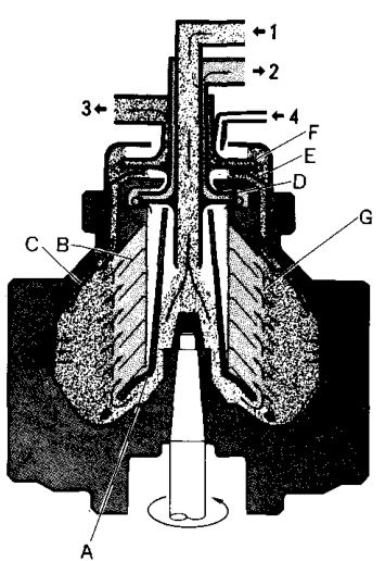
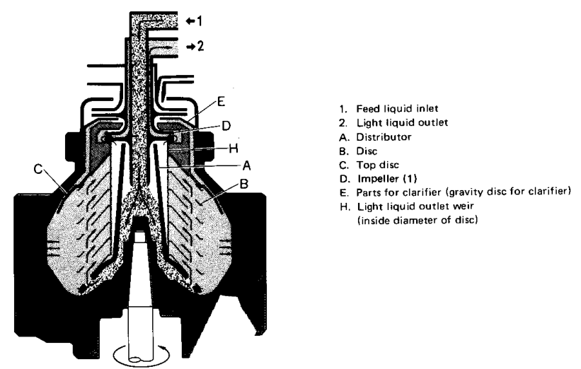
The manufacturer’s diagram identifies the following important items:
- Feed-liquid inlet
- Light-liquid outlet
- Heavy-liquid outlet
- Sealing-water inlet
- Distributor
- Disc stack
- Top disc
- Light-liquid impeller
- Gravity disc
- Heavy-liquid impeller
- Interface
[Purifier—Mitsubishi Selfjector Manual 1, p. 58]
4. External purifier structure
4.1 Frame and casing
The frame supports and encloses the rotating and hydraulic parts. It provides:
- Structural support
- Protection from rotating components
- Mounting points for pipes and valves
- Access for inspection and dismantling
- Containment for oil, water, and sludge
The frame must remain rigid and correctly secured. A loose foundation or damaged frame can transmit vibration to the purifier and connected piping.
4.2 Frame cover
The frame cover encloses the bowl and provides access during maintenance. It must be correctly locked before operation.
Never open the frame cover while the bowl is rotating.
4.3 Bowl casing and sludge cover
The casing contains the bowl and helps direct discharged sludge and water to the drain system.
The sludge cover must be correctly installed because:
- Sludge discharge is high-energy hydraulic flow.
- Leakage can contaminate the purifier room.
- Incorrect seating can affect the discharge path.
- Unbalanced deposits may remain inside the bowl.
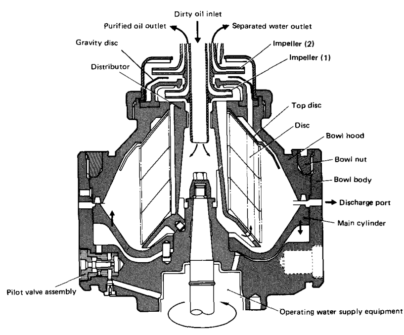
5. The bowl assembly
The bowl is the central separation component. It rotates at high speed and contains the liquid paths.
The main bowl structure consists of:
- Bowl body
- Bowl hood
- Bowl nut
- Sliding bowl bottom or main cylinder
- Disc stack
- Top disc
- Distributor
- Outlet chambers
- Gravity disc
- Sealing rings and O-rings
- Pilot valves and operating-water passages
5.1 Bowl body
The bowl body is the main rotating lower structure. It:
- Forms the lower part of the separation chamber.
- Supports the distributor and disc assembly.
- Provides the outer wall where solids accumulate.
- Contains hydraulic passages and discharge arrangements.
- Rotates with the spindle.
The inner bowl wall is the final collection surface for separated solids.
5.2 Bowl hood
The bowl hood forms the upper part of the rotating container. It:
- Encloses the disc stack.
- Provides the upper liquid-flow region.
- Supports or locates the top-disc and outlet arrangement.
- Forms part of the sealing boundary.
The main seal ring is installed beneath the bowl hood. The dismantling instructions warn that its sealing surface must not be damaged.
5.3 Bowl nut
The bowl nut clamps the bowl assembly together.
It maintains the correct compression of:
- Bowl hood
- Disc stack
- Top disc
- Sealing elements
- Internal chambers
The bowl nut is not simply a cover fastener. Its correct tightening is essential for:
- Disc-stack compression
- Bowl balance
- Hydraulic sealing
- Structural integrity at high speed
The manufacturer gives a special dismantling procedure using a disc clamp plate because removing the bowl nut directly can damage the bowl hood.
6. The rotating spindle and drive
The spindle transfers torque from the drive system to the bowl.
It must provide:
- Correct rotational speed
- Accurate alignment
- Stable support
- Safe transmission of torque
- Minimal vibration
The drive system normally includes:
- Electric motor
- Coupling or friction clutch
- Gears or worm drive, depending on model
- Bearings
- Vertical spindle
- Bowl mounting arrangement
Why spindle condition matters
A damaged, bent, worn, or contaminated spindle can cause:
- Excessive vibration
- Uneven disc loading
- Bowl rubbing
- Bearing damage
- Poor separation
- Dangerous mechanical failure
The bowl and spindle are balanced components. Do not substitute bowl parts casually. The Mitsubishi manual cautions that the bowl has been adjusted in balance and that replacement of bowl parts should be avoided even when the model is the same unless properly authorised.
7. The distributor
The distributor is the first internal flow-control component.
Its purposes are to:
- Receive dirty oil from the inlet.
- Spread the feed toward the separation chamber.
- Bring the incoming liquid close to bowl speed.
- Reduce sudden hydraulic disturbance.
- Feed the outer region of the disc stack.
Reed’s explains that radial vanes in the distributor rapidly bring the oil up to purifier rotational speed before the oil enters the disc passages.
Why acceleration matters
If incoming oil entered the disc stack without being accelerated:
- It would experience strong relative motion against the rotating bowl.
- Turbulence would increase.
- The interface could become unstable.
- Separation efficiency would decrease.
- Mechanical and hydraulic losses would increase.
Distributor maintenance concerns
Check for:
- Blocked passages
- Erosion
- Cracks
- Loose vanes
- Incorrect installation
- Damaged keys or splines
- Foreign material
The distributor also supports or locates the disc stack in many designs.
8. The disc stack
The disc stack is the main separation chamber.
It consists of many closely spaced conical discs mounted together on the distributor or central assembly.
8.1 Function
The disc stack:
- Creates many thin separation passages.
- Shortens the radial settling distance.
- Provides surfaces on which solids can migrate.
- Helps water move outward and oil move inward.
- Increases effective separation area.
- Maintains a controlled flow path.
8.2 Flow in the disc stack
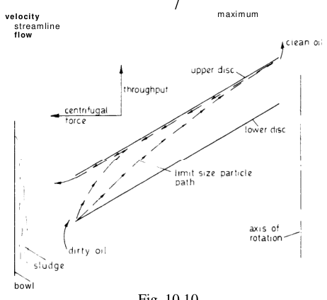
During purifier operation:
The Mitsubishi manual states that dirty oil passes through the spaces between discs, where solids and water are separated before purified oil is discharged through the centripetal pump.
8.3 Disc-stack compression
The discs must be tightly and correctly assembled.
If compression is insufficient:
- Gaps can form between discs.
- Flow distribution becomes uneven.
- Separation efficiency decreases.
- The stack may become unbalanced.
- Disc deformation can occur.
The maintenance material states that a loss of disc-set elasticity can create a gap between the top disc and the disc stack, worsening separation and causing unbalance.
8.4 Disc condition
Inspect for:
- Cracks
- Deformation
- Erosion
- Damaged key grooves
- Bent or torn edges
- Deposits and blocked passages
- Incorrect number of discs
- Poor contact between discs
Cracked discs must be replaced. Do not repair a cracked disc by welding.
9. The top disc
The top disc is located above the main disc stack. It helps define the upper separation and outlet regions.
Its functions include:
- Separating the light-liquid region from the heavy-liquid path.
- Directing heavy liquid toward the gravity-disc area.
- Forming part of the upper hydraulic boundary.
- Helping maintain the correct interface geometry.
- Supporting the outlet flow arrangement.
In the Mitsubishi purifier diagram, heavy liquid passes outside the top disc before reaching the gravity disc and heavy-liquid impeller.
Top-disc condition
A damaged or incorrectly seated top disc can cause:
- Incorrect interface position
- Oil carry-over to the heavy-liquid side
- Water carry-over to clean oil
- Internal leakage
- Poor separation
The top disc must be clean, undamaged, and correctly located during assembly.
10. The gravity disc
The gravity disc is part of the heavy-liquid outlet arrangement.
It controls the effective outlet diameter and therefore the position of the oil-water interface.
10.1 Main function
The gravity disc:
- Controls the heavy-liquid outlet radius.
- Positions the oil-water interface.
- Balances the light-liquid and heavy-liquid outlet conditions.
- Allows the purifier to handle oils of different densities.
The Mitsubishi manual states:
- A larger inside diameter moves the interface outward.
- A smaller inside diameter moves the interface inward.
10.2 Incorrect gravity disc
An incorrect disc can cause:
- Oil flowing out through the heavy-liquid outlet
- Water circulating over the light-liquid side
- Water in clean oil
- Unstable operation
- Poor separation
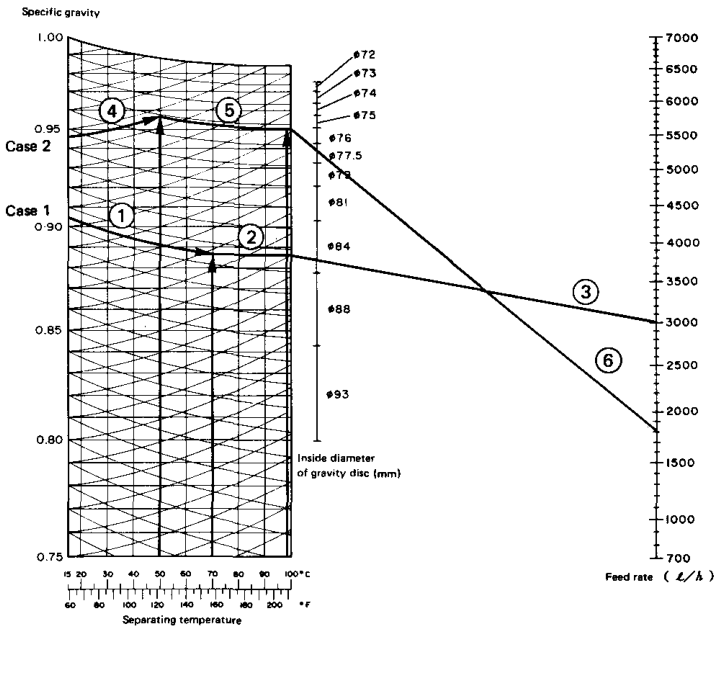
Selection depends on:
- Specific gravity
- Treating temperature
- Feed rate
- Purifier model
10.3 Gravity-disc handling
During maintenance:
- Keep discs clean and identified.
- Do not mix discs from different models or services.
- Check the inside diameter against the manual.
- Install the disc in the correct position.
- Never guess based only on appearance.
11. Light-liquid outlet and impeller
The light-liquid outlet removes purified oil.
The light-liquid impeller is a centripetal pump. It uses the rotating liquid’s energy to discharge the clean oil from the bowl.
Function
The light-liquid outlet arrangement:
- Collects oil from the inner region of the separation chamber.
- Converts rotational energy into discharge pressure.
- Sends purified oil continuously to the outlet line.
- Helps maintain the liquid flow through the bowl.
The Mitsubishi manual identifies this component as impeller (1) and states that purified oil is discharged by the centripetal pump on the upper part of the bowl.
Problems at the light-liquid outlet
Possible symptoms:
- Low clean-oil pressure
- Water in clean oil
- Irregular flow
- Oil leakage
- Excessive back pressure
- Pump or impeller damage
Check for:
- Blockage
- Incorrect assembly
- Damaged impeller
- Excessive outlet restriction
- Incorrect interface position
12. Heavy-liquid outlet and impeller
The heavy-liquid outlet removes separated water and other heavy liquid.
The heavy-liquid impeller is another centripetal pump used to discharge the heavy liquid from the bowl.
Flow path
The heavy-liquid outlet must remain free enough for the water flow to leave the bowl. A blocked outlet can shift the interface or cause water carry-over.
Symptoms of a heavy-liquid outlet problem
- Water mixing with clean oil
- Oil appearing at the water outlet
- Bowl pressure instability
- Overflow
- Incorrect interface position
- Frequent alarms
The Mitsubishi troubleshooting material lists a blocked bowl water outlet as a cause requiring cleaning and discharge-interval adjustment.
13. Interface region
The interface is not a separate solid component. It is the boundary between:
- Light liquid: oil
- Heavy liquid: water
Its position is determined by the hydraulic balance of the bowl.
The interface depends on:
- Oil specific gravity
- Water density
- Separating temperature
- Feed rate
- Outlet conditions
- Gravity-disc diameter
- Back pressure, where applicable
The interface must remain in a region where:
- Oil reaches the clean-oil outlet.
- Water reaches the heavy-liquid outlet.
- Solids move to the bowl wall.
An incorrectly positioned interface is a flow problem, not merely a “dirty oil” problem.
14. Sealing-water inlet
Sealing water is supplied before the oil feed in purifier operation.
Purpose
The sealing-water inlet:
- Supplies water to establish the liquid seal.
- Prevents oil from escaping through the heavy-liquid outlet.
- Creates the initial heavy-liquid region.
- Helps establish the correct interface before feeding oil.
The Mitsubishi manual states that sealing water is supplied through the sealing-water inlet, passes by the gravity disc and outside the top disc, and accumulates at the bowl periphery.
Consequences of poor sealing water
If there is insufficient sealing water:
- Oil may flow to the water outlet.
- The interface may not form correctly.
- Separation may be unstable.
- The purifier may require re-sealing.
If sealing-water flow is excessive:
- Water may mix with the clean oil.
- Water-discharge load may increase.
- The liquid balance may be disturbed.
15. Sliding bowl bottom or main cylinder
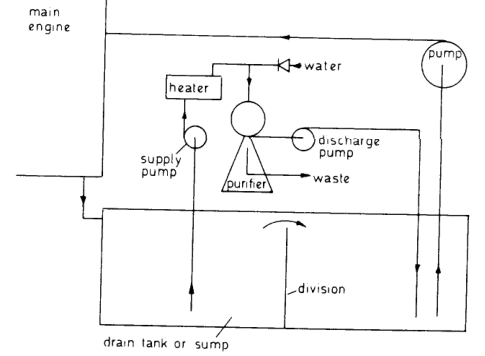
The sliding bowl bottom is the self-cleaning mechanism’s main moving element.
It is hydraulically moved up and down to:
- Close and seal the bowl during normal operation.
- Open discharge ports during sludge ejection.
- Allow accumulated solids to leave the bowl.
The Mitsubishi manual calls this a main cylinder that slides hydraulically to discharge solids accumulated on the inside wall of the bowl.
Normal running position
During purification:
- Operating water pressure holds the sliding bowl bottom closed.
- The bowl remains sealed.
- Solids accumulate at the periphery.
- Oil and water follow their outlet paths.
Discharge position
During sludge discharge:
- Oil feed is stopped or controlled.
- Operating-water valves change state.
- Hydraulic pressure moves the sliding bowl bottom.
- Discharge ports open.
- Sludge and water leave.
- The bowl closes again.
- The liquid seal is restored.
16. Operating-water system
Operating water controls the hydraulic movement of the bowl.
It is different from the oil being purified and must be clean enough to avoid blocking small passages and valves.
The operating-water system may include:
- Operating-water tank
- Reducing valve
- Solenoid valves
- Pilot valves
- Main cylinder chamber
- Opening-water passage
- Closing-water passage
- Drain and discharge passages
- Control timer
Functions
Operating water may be used to:
- Keep the bowl closed.
- Open the bowl for sludge discharge.
- Close the bowl after discharge.
- Establish or restore hydraulic sealing.
- Control partial or total discharge.
Hydraulic principle
Poor operating-water pressure can cause:
- Incomplete discharge
- Bowl opening failure
- Early closing
- Seal leakage
- Sludge remaining in the bowl
- Gasket wear
17. Pilot valves
Pilot valves control the hydraulic signal that moves the sliding bowl mechanism.
The Mitsubishi manual identifies pilot valve assemblies positioned around the bowl body.
They must:
- Open and close at the correct time.
- Respond to the operating-water pressure.
- Remain free from sludge and scale.
- Maintain correct hydraulic sequencing.
A pilot-valve fault may appear as a bowl that:
- Does not open
- Opens incompletely
- Opens too slowly
- Closes too early
- Leaks operating water
- Fails to re-establish the seal
18. Sealing rings, O-rings, and packing
Seals separate the different hydraulic and liquid regions.
They prevent:
- Oil leakage
- Water leakage
- Operating-water loss
- Internal bypass
- Loss of bowl-closing pressure
- Contamination of adjacent chambers
Important sealing parts include:
- Main seal ring
- O-rings
- Seat packing
- Valve-seat seals
- Bowl-hood seals
- Outlet packing
Seal damage symptoms
- Oil leakage from the frame
- Water mixing with oil
- Operating-water loss
- Bowl opening or closing problems
- Loss of outlet pressure
- Unstable interface
Seal surfaces must be cleaned carefully. Scratches, cuts, hardened rubber, or incorrect seating can create failures that appear to be “purifier adjustment” problems.
19. Sludge space and discharge ports
The sludge space is the outer region of the bowl where separated solids accumulate.
It must provide enough capacity between discharges.
Sludge-space functions
- Receive solid particles from the disc stack.
- Hold separated sludge during operation.
- Keep solids away from the clean-oil outlet.
- Direct solids toward discharge ports.
Discharge ports
Discharge ports allow sludge and water to leave during self-cleaning operation.
Blocked ports can cause:
- Incomplete de-sludging
- Rising sludge level
- Reduced separation area
- Disc-stack contamination
- Unbalance
- Increased vibration
The operating interval must match the contamination load. Heavy fuel or dirty lubricating oil may require more frequent discharge.
20. Inlet and outlet pipes
Dirty-oil inlet
The dirty-oil inlet delivers untreated liquid to the distributor.
Check for:
- Correct valve alignment
- Adequate pressure
- No air ingress
- Clean strainer
- Correct temperature
- No restriction
Clean-oil outlet
The clean-oil outlet carries light liquid from the inner bowl region.
Check for:
- Correct back pressure
- No blockage
- Correct discharge pressure
- No water carry-over
Heavy-liquid outlet
The heavy-liquid outlet carries water from the outer liquid region.
Check for:
- Free flow
- No sludge blockage
- Correct outlet arrangement
- No excessive oil carry-over
21. Component-to-function table
| Component | Main function | If defective or incorrectly assembled |
|---|---|---|
| Frame | Supports and encloses machine | Vibration, leakage, structural instability |
| Spindle | Rotates bowl | Vibration, low speed, bearing damage |
| Bowl body | Forms lower rotating container | Leakage, imbalance, poor discharge |
| Bowl hood | Encloses upper bowl | Seal failure, internal leakage |
| Bowl nut | Clamps bowl assembly | Loose stack, damage, unsafe operation |
| Distributor | Accelerates and distributes feed | Turbulence, poor separation, blockage |
| Disc stack | Provides separation passages | Dirty oil, poor clarification, unbalance |
| Top disc | Separates upper flow regions | Incorrect interface, carry-over |
| Gravity disc | Controls heavy-liquid outlet radius | Oil to water side or water to oil side |
| Light-liquid impeller | Discharges clean oil | Low oil pressure, poor outlet flow |
| Heavy-liquid impeller | Discharges water | Water carry-over, unstable interface |
| Sealing-water inlet | Establishes liquid seal | Oil escaping through water outlet |
| Sliding bowl bottom | Opens/closes sludge ports | Incomplete discharge or leakage |
| Pilot valves | Control hydraulic sequence | Bowl fails to open or close |
| O-rings/seal rings | Prevent internal leakage | Oil/water mixing and pressure loss |
| Sludge space | Stores separated solids | Rapid blockage and vibration |
| Discharge ports | Remove sludge | Incomplete de-sludging |
22. Purifier flow through the components
22.1 Oil path
22.2 Water path
22.3 Solids path
22.4 Operating-water path
23. Purifier and clarifier component differences
Some components are used differently in clarifier operation.
In clarifying operation:
- The liquid-solid separation remains.
- The water-seal arrangement is not used in the same way.
- The heavy-liquid outlet path is not used for normal water separation.
- The light liquid moves inward and exits through the light-liquid outlet.
- Solids move to the periphery.
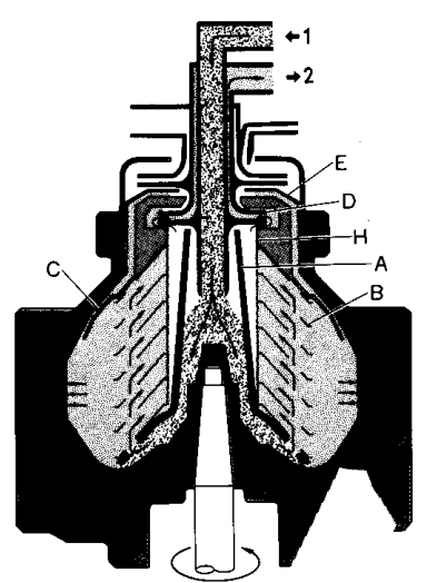
The Mitsubishi manual identifies the clarifier parts as including the distributor, discs, top disc, light-liquid impeller, clarifier gravity-disc arrangement, and light-liquid outlet weir. It states that sealing or replacement water is not supplied in clarifier operation.
24. Dismantling and assembly principles
The purifier bowl is a precision rotating assembly. Dismantling is not ordinary unscrewing and reassembly.
24.1 Before dismantling
- Stop feed.
- Stop the machine.
- Isolate power.
- Confirm the bowl is completely stationary.
- Isolate operating water where required.
- Follow the manufacturer’s tools and sequence.
- Mark or record component positions.
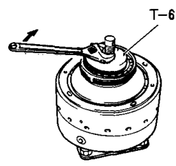
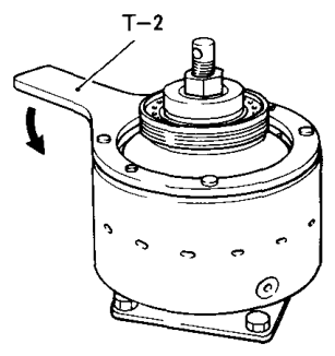
24.2 Bowl nut and disc clamp
The manufacturer specifies use of a disc clamp plate before removing the bowl nut. The clamp compresses the discs and prevents excessive force from being transmitted to the bowl hood.
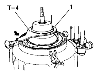
24.3 Gravity-disc removal
The gravity disc is removed with the heavy-liquid chamber, impeller, packing, and related parts according to the maker’s sequence.
24.4 Disc-stack handling
- Keep discs in order.
- Do not drop or bend them.
- Clean each disc carefully.
- Check for cracks and damaged key grooves.
- Confirm the correct number of discs.
- Compress the stack correctly.
- Confirm the top disc is seated.
Incorrect disc assembly can produce poor separation and dangerous imbalance.
25. Component inspection priorities
25.1 Disc stack
Inspect for:
- Cracks
- Erosion
- Deformation
- Deposits
- Incorrect compression
- Missing discs
- Damaged splines or key grooves
25.2 Bowl body and hood
Inspect for:
- Corrosion
- Erosion
- Cracks
- Damaged sealing surfaces
- Distortion
- Sludge deposits
25.3 Gravity disc
Inspect for:
- Correct inside diameter
- Damage
- Deposits
- Incorrect identification
- Damaged seating surface
25.4 Impellers
Inspect for:
- Wear
- Cracks
- Blocked passages
- Loose fit
- Damage to vanes
25.5 Operating-water system
Inspect for:
- Blocked strainers
- Correct pressure
- Solenoid operation
- Pilot-valve operation
- Leakage
- Correct timer sequence
25.6 Seals
Inspect for:
- Cuts
- Hardening
- Flattening
- Incorrect seating
- Chemical attack
- Abrasion
26. Troubleshooting by component
Problem: Oil flows to the water outlet
Likely component or setting causes:
- Wrong gravity disc
- Damaged top disc
- Poor water seal
- Incorrect bowl assembly
- Heavy-liquid outlet problem
- Incorrect interface position
Problem: Water enters clean oil
Likely causes:
- Wrong gravity disc
- Excessive sealing or replacement water
- Blocked water outlet
- Incorrect top-disc or outlet assembly
- Excessive feed rate
- Incorrect liquid properties
Problem: Poor separation
Likely causes:
- Dirty disc stack
- Damaged discs
- Distributor blockage
- Incorrect temperature
- Excessive feed rate
- Low bowl speed
- Incorrect interface
Problem: Bowl does not open for sludge discharge
Likely causes:
- Low operating-water pressure
- Blocked pilot valve
- Blocked operating-water passage
- Faulty solenoid valve
- Incorrect discharge timer
- Sludge packed around the sliding bowl bottom
Problem: Bowl opens or closes incorrectly
Likely causes:
- Seal-ring damage
- Incorrect operating-water flow
- Pilot-valve fault
- Sliding-cylinder contamination
- Incorrect hydraulic timing
Problem: Excessive vibration
Likely causes:
- Uneven sludge deposits
- Incorrect disc count
- Poor disc compression
- Bowl-part substitution
- Damaged spindle or bearing
- Foreign material inside the bowl
- Incorrect bowl assembly
27. Component fault-tracing method
Use this sequence instead of replacing parts randomly:
Examples:
- Water in clean oil → trace water/interface/light-liquid path.
- Oil at water outlet → trace heavy-liquid path and gravity disc.
- Bowl not opening → trace operating-water and sliding-cylinder path.
- Vibration → trace rotating assembly and sludge distribution.
- Low clean-oil pressure → trace light-liquid impeller and outlet path.
28. Revision questions with answers
Question 1
What are the three main structural parts of the bowl?
Answer: Bowl body, bowl hood, and bowl nut.
Question 2
What is the function of the distributor?
Answer: It distributes the feed and accelerates the oil toward bowl speed before the oil enters the disc stack.
Question 3
What is the function of the disc stack?
Answer: It provides many short separation passages and surfaces that help water and solids move outward while oil moves inward.
Question 4
What is the function of the top disc?
Answer: It helps separate the upper flow regions and directs the heavy liquid toward the gravity-disc and water-outlet arrangement.
Question 5
What does the gravity disc control?
Answer: It controls the heavy-liquid outlet diameter and the position of the oil-water interface.
Question 6
What is the light-liquid impeller used for?
Answer: It discharges purified oil from the bowl.
Question 7
What is the heavy-liquid impeller used for?
Answer: It discharges separated water or other heavy liquid.
Question 8
What is the purpose of sealing water?
Answer: It establishes the liquid seal and prevents oil from leaving through the heavy-liquid outlet.
Question 9
What does the sliding bowl bottom do?
Answer: It keeps the bowl sealed during operation and opens discharge ports during sludge ejection.
Question 10
Why is the bowl nut important?
Answer: It clamps the bowl and disc assembly, maintaining compression, sealing, and structural integrity.
Question 11
Why must bowl parts not be casually exchanged?
Answer: The rotating bowl is precision-balanced, and incorrect parts can cause imbalance, vibration, and unsafe operation.
Question 12
What can cause incomplete sludge discharge?
Answer: Low operating-water pressure, blocked passages or valves, incorrect timing, or sludge packed around the sliding mechanism.
29. Self-test drawing exercise
Draw a purifier cross-section and label all of the following:
- Bowl body
- Bowl hood
- Bowl nut
- Spindle
- Distributor
- Disc stack
- Top disc
- Gravity disc
- Light-liquid impeller
- Heavy-liquid impeller
- Interface
- Sealing-water inlet
- Sludge space
- Sliding bowl bottom
- Clean-oil outlet
- Heavy-liquid outlet
- Sludge-discharge ports
Then use three colours:
- Blue: water and operating water
- Yellow: oil
- Brown: sludge and solids
Trace each colour from inlet to outlet. If a component is not part of a trace, explain what mechanical or hydraulic job it performs.
30. One-minute component test
Without looking at the manual, answer:
- Where does dirty oil enter?
- Which component accelerates it?
- Where does separation mainly occur?
- Which component controls the interface?
- Which impeller discharges clean oil?
- Which impeller discharges water?
- Where do solids accumulate?
- Which moving part opens the bowl for sludge discharge?
- What fluid controls that movement?
- What prevents oil from entering the water outlet at start-up?
Correct sequence: