
Purifier Normal Operation and Monitoring
How do you know that a purifier is running normally?
Key Principles at a Glance 8 points
- Normal operation is a combination of readings rather than one green lamp: speed, current, vibration, sound, temperatures, pressures and oil quality must all be right together.
- Motor current and bowl speed together show whether the bowl is at rated speed and whether the load is normal.
- Rising vibration or a change in operating sound is the earliest warning of bowl imbalance, sludge build-up or a mechanical fault.
- Feed temperature and feed rate must be held at the recommended values, because deviation changes viscosity and residence time and shows up as poor oil quality.
- Light-liquid outlet pressure, heavy-liquid outlet flow and clean-oil quality are the direct evidence that separation is working.
- The Leakage Monitor, Water Detector and Discharge Detector supervise seal condition, water carry-over and correct sludge discharge.
- Operation should be logged and compared with the previous discharge cycle, because the trend rather than the single reading reveals deterioration.
- An alarm calls for a defined response, and the machine should be stable again after each sludge discharge.
1. Learning objectives
Course position: Topic 10 of the purifier learning sequence
Main question: How do you know that a purifier is running normally?
After studying this lesson, you should be able to:
- Define normal purifier operation.
- Identify the values that must be monitored during running.
- Explain the meaning of current, speed, vibration, temperature, pressure, and outlet conditions.
- Use the Multi-Monitor functions described in the Selfjector manual.
- Distinguish normal transient conditions from abnormal running.
- Check clean-oil and heavy-liquid outlet behaviour.
- Monitor sludge discharge and water detection.
- Recognise early signs of mechanical, hydraulic, thermal, and separation faults.
- Maintain a useful purifier log.
- Respond correctly to abnormal readings.
2. What normal operation means
A purifier is operating normally when it maintains all of these conditions together:
- Bowl speed is stable.
- Vibration and sound are normal.
- Motor current is stable.
- Feed oil temperature is at the selected value.
- Feed rate is at the planned value.
- Light-liquid outlet pressure is correct.
- Water outlet flow is appropriate.
- No oil escapes through the sludge or water outlet.
- No water appears in clean oil.
- Sludge discharge occurs at the required interval.
- The bowl remains closed between discharge operations.
- Alarms, detectors, and automatic controls remain healthy.
Normal operation is not proved by one green lamp. It is confirmed by the combination of readings, sound, vibration, outlet behaviour, and oil quality.
3. The monitoring system
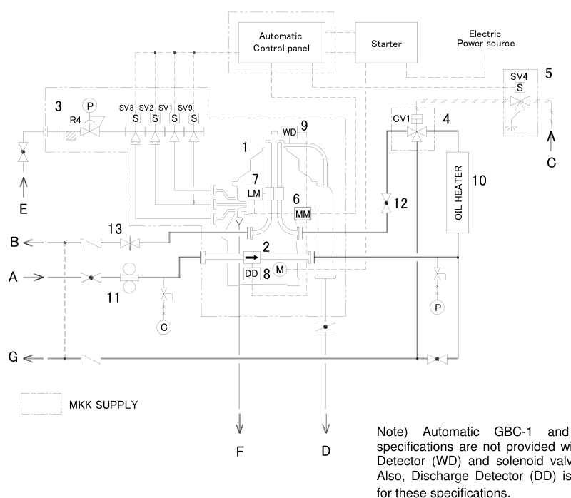
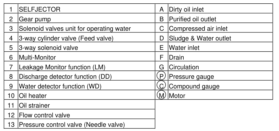
A typical automatic Selfjector system may include:
- Starter
- Gear pump
- Oil heater
- Oil strainer
- Flow-control valve
- Pressure-control valve
- Solenoid-valve unit
- Multi-Monitor
- Leakage Monitor function
- Discharge Detector function
- Water Detector function
- Pressure sensors
- Temperature sensor
- Revolution sensor
- Circulation line
The Mitsubishi manual’s typical system diagram identifies these components and their connections.
A second version of the same system arrangement is also provided in the manual:
4. The main operating values
Monitor these values during normal running:
| Value | What it tells you |
|---|---|
| Bowl speed | Whether centrifugal force is available |
| Motor current | Mechanical and electrical load |
| Vibration | Balance, bearings, bowl, and sludge condition |
| Operating sound | Drive, bearing, rubbing, and hydraulic condition |
| Feed temperature | Viscosity and separation condition |
| Feed rate | Residence time and treatment capacity |
| Feed pressure | Pump and inlet-flow condition |
| Light-liquid pressure | Clean-oil outlet and hydraulic balance |
| Water outlet | Heavy-liquid discharge condition |
| Leakage monitor | Oil or water leakage into unintended areas |
| Water detector | Water carry-over or water condition |
| Discharge detector | Confirmation of sludge-discharge operation |
| Sludge interval | Contamination loading and bowl capacity |
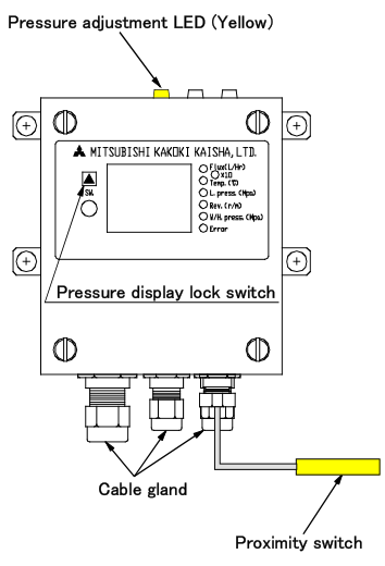
The Multi-Monitor can display flow rate, temperature, pressure, rotation number, and other values. Depending on model, it also provides leakage, discharge, and water-detection functions.
5. Bowl speed
Bowl speed determines the centrifugal force available for separation.
Normal condition
- Speed reaches the maker’s rated value.
- Speed remains stable during treatment.
- No abnormal speed alarm appears.
- The speed indication does not fluctuate unexpectedly.
Low-speed consequences
Low speed can result from:
- Motor fault
- Friction-clutch slip
- Gear or drive fault
- Bearing damage
- Excessive mechanical resistance
- Electrical supply problem
Do not continue normal feed when the bowl cannot maintain rated speed.
6. Motor current
Motor current is a useful indicator of starting and running load.
During start-up
Current is normally higher while the bowl accelerates. It should settle as the purifier reaches rated speed.
The Mitsubishi start-up instruction gives a typical settled value of approximately 50–70% of rated current for the referenced equipment.
During stable running
A stable current indicates a stable mechanical load, provided the reading is within the maker’s expected range.
Rising current may indicate
- Bearing friction
- Bowl rubbing
- Sludge accumulation
- Drive fault
- Incorrect bowl assembly
- Pump overload
- Excessive oil resistance
- Electrical motor fault
Falling or unstable current may indicate
- Loss of mechanical load
- Friction-clutch slip
- Feed-pump change
- Intermittent drive engagement
- Electrical problem
Current must be interpreted with vibration, speed, sound, and pressure. It is not a standalone diagnosis.
7. Vibration
Vibration is one of the most important purifier safety indicators.
Normal transient vibration
Some vibration may occur briefly while the bowl passes through a critical speed during acceleration. The Mitsubishi manual states that this should reduce when rated speed is achieved.
Abnormal vibration
Large or persistent vibration at rated speed requires immediate stopping and inspection.
Possible causes:
- Uneven sludge accumulation
- Incorrect disc count
- Poor disc-stack compression
- Damaged disc
- Bowl-part imbalance
- Bent spindle
- Bearing damage
- Bowl rubbing
- Loose foundation
- Foreign material inside the bowl
Never open the frame cover until the bowl has completely stopped.
8. Operating sound
A purifier should have a consistent operating sound after acceleration.
Listen for:
- Bearing noise
- Rubbing or contact sound
- Gear noise
- Repeated knocking
- Unusual hydraulic noise
- Sludge-discharge sound
The Mitsubishi manual instructs the operator to stop immediately when abnormal sound is heard and to identify the cause.
Sound changes can indicate
| Sound | Possible area |
|---|---|
| Scraping/contact | Bowl, cover, disc, or spindle alignment |
| Repeated knocking | Loose or damaged rotating part |
| Harsh bearing noise | Bearing or lubrication problem |
| Sudden hydraulic discharge sound | Automatic sludge discharge |
| No expected discharge sound | Discharge failure or blocked path |
Use sound together with current and vibration trends.
9. Feed temperature
Feed temperature controls viscosity and therefore separation efficiency.
Monitor:
- Heater inlet temperature
- Heater outlet temperature
- Feed temperature at the purifier
- Temperature stability
- High-temperature alarms
The Mitsubishi manual warns that feed-temperature fluctuations can change viscosity and therefore alter light-liquid outlet pressure and leakage-monitor behaviour.
Temperature instability
Possible causes:
- Heater fault
- Steam or electrical supply problem
- Temperature-control valve fault
- Poor circulation
- Incorrect sensor
- Changing feed condition
- Excessive or insufficient flow
Do not adjust the gravity disc to compensate for a heater fault before correcting the temperature condition.
10. Feed rate
Feed rate determines how much oil is treated and how long the liquid remains in the bowl.
Normal feed-rate condition
- Flow matches the selected operating condition.
- Feed remains stable.
- Flow-control and bypass valves are correctly positioned.
- The gravity-disc selection matches the feed rate.
The Mitsubishi instructions tell the operator to regulate the bypass and flow-control valves to a given feed rate and confirm the value on the Multi-Monitor.
Feed rate too high
- Residence time decreases.
- Fine solids may pass through.
- Water separation may deteriorate.
- Interface can become unstable.
- Outlet pressure can change.
Feed rate too low
- Production capacity decreases.
- Oil may remain heated longer than necessary.
- The system may not meet the required treatment demand.
- Excessively low flow may affect automatic-monitor settings.
The correct feed rate is the rate that meets both treatment capacity and required oil cleanliness.
11. Feed pressure and inlet condition
Feed pressure confirms that the gear pump and inlet path are supplying the purifier correctly.
Check for:
- Stable pump pressure
- No sudden pressure drop
- No excessive pressure rise
- No air entering the suction line
- Clean strainer
- Open inlet valve
- Correct bypass position
Low feed pressure may indicate
- Empty or low-level supply tank
- Pump wear
- Suction blockage
- Air leakage
- Closed valve
- Strainer blockage
- Excessive bypass
High feed pressure may indicate
- Closed or restricted valve
- Blocked strainer
- Excessive viscosity
- Heater problem
- Downstream restriction
12. Light-liquid outlet pressure
The light-liquid outlet pressure is the pressure of the purified-oil discharge line.
The Mitsubishi system uses a pressure-control valve in the light-liquid outlet line. The manual gives a standard example of approximately 0.15 MPa, or 1.5 kgf/cm², for the referenced system.
The exact value for the installed purifier must come from its manual.
Why pressure matters
Light-liquid pressure affects:
- Oil discharge
- Internal hydraulic balance
- Interface condition
- Leakage-monitor function
- Stable outlet flow
The manual states that the light-liquid outlet pressure is critical for correct leakage-monitor operation.
Pressure too low
Possible causes:
- Open or incorrectly adjusted back-pressure valve
- Low feed rate
- Pump problem
- Internal leakage
- Outlet-line condition
- Interface disturbance
Pressure too high
Possible causes:
- Excessive back pressure
- Restricted outlet line
- Incorrect valve position
- High viscosity
- Incorrect flow condition
Do not adjust pressure without confirming the feed rate and temperature.
13. Heavy-liquid outlet and water flow
The heavy-liquid outlet carries separated water.
Monitor:
- Water flow
- Oil carry-over
- Sudden loss of water discharge
- Sludge presence
- Outlet-line blockage
- Water pressure or detector response
Normal water-outlet condition
- Water leaves consistently according to the oil’s water loading.
- Excessive oil is not present.
- The outlet is not blocked.
- The interface remains stable.
Oil at the water outlet
Check:
- Gravity disc
- Sealing water
- Oil specific gravity
- Treating temperature
- Feed rate
- Interface position
- Heavy-liquid outlet restriction
No water flow
Possible reasons:
- Low water contamination
- Blocked outlet
- Incorrect interface
- Water-seal problem
- Heavy-liquid impeller or chamber problem
14. Clean-oil quality
The clean-oil outlet is the final practical test of separation performance.
Check for:
- Free water
- Sediment
- Cloudiness
- Unusual colour
- Sludge or fine particles
- Abnormal odour from contamination
Clean-oil quality should be checked using the methods available on board and through laboratory analysis where required.
Poor clean-oil quality can result from:
- Incorrect temperature
- Excessive feed rate
- Wrong gravity disc
- Poor water seal
- Dirty disc stack
- Low bowl speed
- High water or solids loading
- Incorrect bowl assembly
15. Leakage Monitor function
The Leakage Monitor function detects abnormal liquid leakage conditions and depends on correct light-liquid outlet pressure.
The Mitsubishi manual states that the pressure must be adjusted to the level preset in the Multi-Monitor through the back-pressure control valve.
Why calibration matters
If normal outlet pressure is wrong:
- The monitor may alarm unnecessarily.
- A real leak may not be detected correctly.
- The operator may misinterpret the purifier condition.
During normal operation:
- Monitor pressure indication.
- Check the pressure-control LED.
- Confirm no unexplained leakage alarm.
- Recheck after large temperature or flow changes.
The manual states that once adjusted during trial operation, light-liquid outlet pressure normally requires no further adjustment unless flow rate or temperature fluctuates.
16. Water Detector function
A water detector identifies water-related conditions in the treated liquid or outlet system, depending on the installed configuration.
The Multi-Monitor types provide different detection functions:
- MM-1, MM-2, MM-3 may provide leakage monitoring.
- MM-2 and MM-3 may provide discharge detection.
- MM-3 may provide water detection.
[Purifier—Mitsubishi Selfjector Manual 2, p. 15]
A water alarm should trigger checks of:
- Water carry-over
- Interface
- Gravity disc
- Sealing and replacement water
- Heavy-liquid outlet
- Feed rate
- Oil temperature
Do not repeatedly reset a water alarm without identifying the cause.
17. Discharge Detector function
The Discharge Detector confirms that an automatic sludge-discharge operation has occurred.
Evidence of discharge may include:
- Current change
- Discharge sound
- Detector response
- Water or sludge movement
- Control-panel sequence
If discharge is not detected:
- Sludge may remain in the bowl.
- Bowl capacity decreases.
- Separation quality may deteriorate.
- Unbalance may develop.
- Vibration may increase.
The Mitsubishi start-up procedure specifically tells the operator to confirm discharge by the increase in current reading or discharge sound.
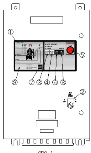
18. Automatic control panel and Multi-Monitor
The control panel coordinates:
- Start
- Automatic start
- Automatic stop
- Feed-valve operation
- Water solenoids
- Bowl opening and closing
- Sludge discharge
- Water sealing
- Alarm and detector functions
The Mitsubishi manual states that AUTO START begins the predetermined sequence after rated speed is reached, while AUTO STOP switches the feed valve to bypass, performs water replacement and sludge discharge, and then stops the motor.
Operator responsibility
Automatic control does not remove the need to:
- Check actual readings.
- Listen to the machine.
- Observe outlet conditions.
- Confirm discharge.
- Record trends.
- Respond to alarms.
19. Sludge-discharge monitoring
During normal running, solids accumulate at the bowl periphery. The purifier must discharge sludge at the planned interval.
Monitor:
- Discharge interval
- Discharge sound
- Current change
- Detector response
- Sludge quantity
- Water quantity
- Bowl vibration after discharge
Discharge too infrequent
- Sludge space fills.
- Flow passages become contaminated.
- Bowl balance may deteriorate.
- Separation becomes poorer.
Discharge too frequent
- More oil may be lost.
- More water may be consumed.
- Production capacity may decrease.
- Mechanical and hydraulic cycling increases.
The correct interval depends on oil type, contamination, feed rate, and purifier model.
20. Normal operating log
A purifier log should record trends, not only isolated values.
| Time | Speed | Current | Feed temp. | Feed rate | Light-liquid pressure | Water outlet | Vibration | Discharge | Remarks |
|---|---|---|---|---|---|---|---|---|---|
| Start | |||||||||
| Stable | |||||||||
| After discharge | |||||||||
| End of watch |
Record:
- Actual values
- Alarm events
- Valve adjustments
- Fuel or oil change
- Heater changes
- Discharge observations
- Clean-oil quality
- Vibration or sound changes
Why trends matter
A slow increase in current or vibration may reveal deterioration before an alarm occurs.
A gradual change in pressure may indicate:
- Flow restriction
- Temperature change
- Interface shift
- Pump wear
- Leakage
21. Normal versus abnormal conditions
| Parameter | Normal indication | Abnormal indication |
|---|---|---|
| Speed | Stable rated speed | Low or fluctuating speed |
| Current | Settled and stable | Rising, high, or unstable |
| Vibration | Low after acceleration | Large or persistent at speed |
| Sound | Consistent | Rubbing, knocking, harsh bearing sound |
| Temperature | Stable selected value | Low, high, or fluctuating |
| Feed rate | Planned value | Excessive, low, or unstable |
| Light pressure | Correct preset range | Low, high, or rapidly changing |
| Water outlet | Expected water flow | Oil carry-over, blockage, no flow |
| Clean oil | Dry and clean | Water, sediment, fine solids |
| Discharge | Confirmed at interval | No discharge or incomplete discharge |
| Leakage monitor | Normal indication | Alarm or unexplained fluctuation |
22. Fault diagnosis by symptom
Symptom: high current
Check:
- Bowl speed
- Vibration
- Sound
- Bearing and drive
- Sludge loading
- Pump and oil viscosity
- Bowl assembly
Symptom: low light-liquid pressure
Check:
- Feed rate
- Feed temperature
- Back-pressure valve
- Outlet line
- Internal leakage
- Interface condition
- Pump condition
Symptom: water in clean oil
Check:
- Gravity disc
- Water seal
- Water flow
- Water outlet
- Feed temperature
- Feed rate
- Specific gravity
Symptom: oil at water outlet
Check:
- Interface
- Gravity disc
- Sealing water
- Feed condition
- Heavy-liquid outlet
- Bowl assembly
Symptom: no sludge discharge
Check:
- Operating-water pressure
- Solenoids
- Pilot valves
- Discharge ports
- Timer
- Sludge packing
- Discharge detector
Symptom: increasing vibration after several hours
Check:
- Sludge accumulation
- Discharge interval
- Disc-stack cleanliness
- Bowl balance
- Bearings
- Foundation
23. Stable running after sludge discharge
After an automatic discharge:
- Confirm the bowl closes.
- Confirm the water seal is restored.
- Confirm feed resumes only after the programmed sequence.
- Check light-liquid pressure.
- Check water outlet.
- Check for oil at sludge or water outlets.
- Check current and vibration.
- Confirm the detector returns to normal.
The Mitsubishi manual notes that pressure and flow conditions after discharge may need time to return to preset values.
Do not increase feed immediately after discharge just because the outlet appears temporarily clear.
24. Normal operation flow chart
25. Operator response to an alarm
When an alarm occurs:
- Read the alarm and identify the parameter.
- Check whether feed should be stopped automatically or manually.
- Observe current, speed, vibration, temperature, and pressure.
- Check clean-oil and water outlets.
- Follow the maker’s alarm procedure.
- Do not reset repeatedly without identifying the cause.
- Record the event and corrective action.
- Inspect the purifier if the alarm indicates a mechanical or bowl fault.
Mechanical alarms
Treat as urgent:
- High vibration
- Abnormal sound
- Low speed
- High current
- Bearing temperature
Separation alarms
Investigate:
- Water detector
- Leakage monitor
- Outlet pressure
- Oil or water carry-over
Hydraulic alarms
Investigate:
- Operating-water pressure
- Bowl opening/closing
- Solenoid valves
- Discharge sequence
26. Common monitoring mistakes
Mistake 1: Watching only the control panel
A panel may not reveal a gradual change in sound, vibration, or outlet quality.
Mistake 2: Ignoring trends
One normal reading does not prove that the purifier will remain healthy.
Mistake 3: Adjusting several valves simultaneously
Change one relevant condition at a time so the result can be understood.
Mistake 4: Adjusting back pressure without checking temperature
Temperature changes viscosity and may change outlet pressure naturally.
Mistake 5: Resetting alarms repeatedly
An alarm is information about a condition, not merely a nuisance.
Mistake 6: Continuing with high vibration
High vibration can damage the bowl, bearings, spindle, and frame.
Mistake 7: Assuming discharge occurred because the timer ran
Confirm discharge through sound, current, detector, or visible system response.
27. Revision questions with answers
Question 1
What proves that a purifier is running normally?
Answer: Stable speed, current, sound, vibration, temperature, feed rate, outlet pressure, outlet quality, and automatic-control behaviour.
Question 2
What does the Multi-Monitor display?
Answer: Depending on model, flow rate, temperature, pressure, rotation number, leakage, discharge, and water-detection information.
Question 3
What happens to current after the bowl reaches speed?
Answer: It should settle within the maker’s expected operating range.
Question 4
What vibration can be normal during starting?
Answer: Temporary vibration while passing through a critical speed.
Question 5
What vibration is abnormal?
Answer: Large or persistent vibration at rated speed.
Question 6
Why must feed temperature be stable?
Answer: Temperature changes viscosity and can affect separation and light-liquid pressure.
Question 7
Why is light-liquid outlet pressure important?
Answer: It affects hydraulic balance, oil discharge, and leakage-monitor function.
Question 8
What does the water detector indicate?
Answer: A water-related condition in the installed monitoring arrangement, requiring checks of water carry-over, interface, seal, and outlet flow.
Question 9
How can sludge discharge be confirmed?
Answer: Through current change, discharge sound, detector response, or system observation.
Question 10
What can rising current and vibration together indicate?
Answer: Mechanical resistance, sludge accumulation, imbalance, bearing trouble, or bowl/drive problems.
Question 11
What should be done if oil appears at the water outlet?
Answer: Check interface, gravity disc, water seal, temperature, feed rate, and heavy-liquid outlet.
Question 12
What should be done after an abnormal alarm?
Answer: Identify the parameter, follow the stopping/feed procedure, investigate the cause, record it, and do not repeatedly reset without correction.
28. Self-test operating log exercise
Create a log for one watch with these fields:
Then answer:
- Which values should remain nearly stable?
- Which value may change after sludge discharge?
- Which reading would make you stop immediately?
- Which readings should be compared together?
- What trend could indicate a developing fault before an alarm?
29. Daily monitoring checklist
- [ ] Rated bowl speed confirmed.
- [ ] Motor current stable.
- [ ] Vibration normal.
- [ ] Sound normal.
- [ ] Feed temperature stable.
- [ ] Feed rate at planned value.
- [ ] Feed pressure normal.
- [ ] Light-liquid pressure within specified range.
- [ ] Water outlet free and normal.
- [ ] No oil at water or sludge outlet.
- [ ] Clean oil free of visible water and sediment.
- [ ] Leakage monitor normal.
- [ ] Water detector normal.
- [ ] Discharge detector normal.
- [ ] Sludge discharge interval appropriate.
- [ ] No abnormal alarm history.
- [ ] Values entered in the purifier log.