
Purifier Automatic Sludge Discharge and Bowl Cleaning
How does a self-cleaning purifier remove accumulated sludge and restore normal operation?
Key Principles at a Glance 8 points
- Sludge must be removed before the sludge space fills, because a full bowl loses separating area and separation collapses.
- A self-cleaning purifier discharges by hydraulically dropping the sliding bowl bottom, so the bowl wall opens momentarily and the sludge is thrown out.
- Total discharge empties the whole sludge space; partial discharge releases only part of it and is used to limit oil loss.
- Operating water does three separate jobs: opening water drops the bowl bottom, closing water raises and seals it, and sealing or replacement water maintains the liquid seal.
- Discharge timing is set by timers and must be matched to the contamination load — too long an interval overloads the bowl, too short a one wastes oil.
- Discharge must be confirmed by the Discharge Detector, by sound or by a current change; an unconfirmed discharge means the bowl did not open.
- Fuel-oil and lubricating-oil duties use different discharge practice, and lubricating-oil bowls are washed during operation.
- If the bowl will not open, closes too early, loses excess oil or trips the water detector repeatedly, suspect the operating-water system or the timer setting first.
1. Learning objectives
Course position: Topic 11 of the purifier learning sequence
Main question: How does a self-cleaning purifier remove accumulated sludge and restore normal operation?
After studying this lesson, you should be able to:
- Explain why sludge must be removed from the bowl.
- Distinguish total discharge from partial discharge.
- Explain the functions of operating water, closing water, opening water, sealing water, and replacement water.
- Describe the sliding bowl bottom or main-cylinder mechanism.
- Trace a complete automatic sludge-discharge cycle.
- Explain timer and solenoid-valve functions.
- Explain lubricating-oil bowl washing.
- Select the correct logic for fuel-oil and lubricating-oil discharge.
- Recognise incomplete discharge and no-discharge faults.
- Explain the safe procedure for a manual sludge discharge during feeding.
- Diagnose problems using current, sound, detector, pressure, and outlet observations.
2. Why sludge discharge is necessary
During purification, solids move to the bowl wall and accumulate in the sludge space.
If sludge remains too long:
- Bowl capacity decreases.
- Disc passages become contaminated.
- Separation efficiency falls.
- Solids may be carried back into the liquid stream.
- The bowl becomes unbalanced.
- Vibration may increase.
- Discharge ports may become blocked.
- Mechanical parts may be damaged.
McGeorge explains that solids collect at the bowl periphery and that the oil feed is stopped at intervals so the bowl can open and discharge the solids through ports. After discharge, the bowl closes and the liquid seal is re-established before oil feed continues.
3. What is a self-cleaning purifier?
A self-cleaning purifier uses hydraulic operating water to open and close the bowl without dismantling it after every discharge.
The main moving part is commonly called:
- Sliding bowl bottom
- Main cylinder
- Operating slide, depending on purifier design
During normal purification:
- Operating water keeps the moving bowl part closed.
- The sliding part presses against a sealing ring.
- Oil, water, and solids remain within their intended paths.
During sludge discharge:
- The oil feed is stopped or diverted.
- Operating-water valves change position.
- Hydraulic pressure moves the sliding part.
- Discharge ports open.
- Sludge and water leave.
- The bowl closes again.

4. Total discharge and partial discharge
The Mitsubishi manual defines:
- Total discharge: the total contents of the bowl are discharged.
- Partial discharge: only the separated water and solids are discharged while the bowl retains the main oil charge.
4.1 Total discharge
In total discharge:
- Oil feed is stopped or diverted.
- The bowl opens more fully.
- Water, sludge, and contained liquid are discharged.
- The bowl is closed again.
- Sealing water is restored.
- Oil feed resumes.
4.2 Partial discharge
In partial discharge:
- Separated water and sludge are discharged.
- The bowl does not empty in the same way as total discharge.
- Less treated oil may be lost.
- The cycle is useful for frequent water removal.
The exact hydraulic sequence depends on purifier model and automatic-control configuration.
4.3 Comparison
| Feature | Total discharge | Partial discharge |
|---|---|---|
| Bowl contents | Mainly all discharged | Water and solids discharged |
| Oil loss | Potentially greater | Normally lower |
| Main purpose | Sludge removal and full clearing | Frequent water/solid removal |
| Re-sealing | Required | Required according to model |
| Bowl washing | May follow for lubricating oil | May be separate or programmed |
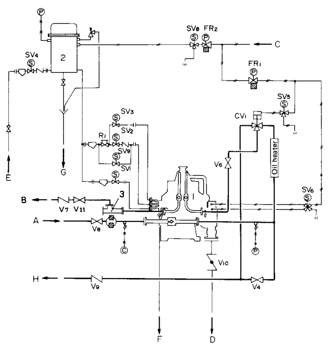
5. Main hydraulic components
The discharge system may include:
- Operating-water tank
- Reducing valve
- Solenoid-valve unit
- Closing-water passage
- Opening-water passage
- Sealing-water passage
- Replacement-water passage
- Pilot valves
- Main-cylinder chamber
- Sliding bowl bottom
- Discharge ports
- Sludge chute
- Water drains
- Automatic timer and control panel
The Mitsubishi manual states that the operating-water solenoid unit controls water for:
- Opening the bowl
- Closing the bowl
- Sealing water
- Replacement water
[Purifier—Mitsubishi Selfjector Manual 2, p. 19]
6. Operating water during normal purification
During normal running, operating water holds the sliding bowl mechanism in its closed position.
The closed bowl allows:
- Oil to remain in the separation chamber.
- Water to pass to the heavy-liquid outlet.
- Solids to accumulate at the bowl wall.
- The purifier to continue normal operation.
If operating-water pressure is too low:
- The bowl may leak.
- The bowl may open unexpectedly.
- Sludge discharge may be incomplete.
- The seal may not be maintained.
7. Opening water
Opening water is pressure water used to move the main cylinder or sliding bowl bottom into the open position.
The Mitsubishi manual states that opening water forces the main cylinder down to open the bowl and release sludge and water accumulated during total or partial discharge.
Opening water must be supplied for the correct time and at the correct pressure.
Too little or too short a supply may produce:
- Partial opening
- Incomplete discharge
- Sludge remaining in the bowl
Too much or too long a supply may produce:
- Excessive water consumption
- Unnecessary oil loss
- Hydraulic shock
- Seal wear
8. Closing water
Closing water moves the bowl mechanism back to the sealed position.
The bowl must be fully closed before normal oil feed resumes.
A bowl that closes too early may press solids into the gasket. A bowl that fails to close may leak oil, water, and operating water.
9. Sealing water and replacement water
These water supplies have different purposes.
9.1 Sealing water
Sealing water establishes the oil-water liquid seal and prevents oil from escaping through the heavy-liquid outlet.
9.2 Replacement water
Replacement water restores the liquid arrangement after discharge and helps prepare the bowl for renewed purification.
Incorrect water timing can cause:
- Oil at the water outlet
- Water in clean oil
- Unstable interface
- False leakage alarms
- Poor restart after discharge
10. Automatic discharge cycle
A typical automatic cycle is:
The Mitsubishi timing diagram shows the relationship between the purifying period, feed-valve closing, opening water, sludge discharge, closing water, replacement water, sealing water, and feed restart.
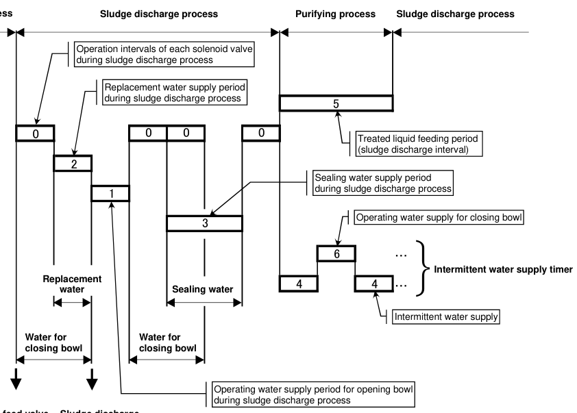
11. Timer settings
The automatic control panel contains timers that control:
- Feed-valve closing
- Opening-water period
- Sludge-discharge period
- Closing-water period
- Sealing-water period
- Replacement-water period
- Intermittent water supply
- Treated-liquid feeding period
- Sludge-discharge interval
- Bowl washing, where applicable
The Mitsubishi manual states that correct timer settings are essential for normal and efficient operation, and that settings vary with operating-water flow rate.
Incorrect timer settings can cause
- Bowl opening too briefly
- Incomplete discharge
- Bowl closing too soon
- Sludge pressed into seals
- Insufficient sealing water
- Feed restarting too early
- Excessive water consumption
- False discharge confirmation
Never change timer values without checking the correct purifier type, water flow, and manufacturer’s tables.
12. Discharge timing and contamination load
Discharge interval depends on:
- Fuel or oil type
- Solids concentration
- Water content
- Feed rate
- Purifier size
- Bowl capacity
- Engine operation
- Water-detector commands
The Mitsubishi HIDENS table gives example intervals for automatic GSH-1 operation:
| Treated oil | Example sludge-discharge interval |
|---|---|
| A heavy oil | 120 minutes |
| C heavy oil | 60 minutes |
| Cross-head-engine lubricating oil | 120 minutes |
| Trunk-piston-engine lubricating oil | 60 minutes |
These are manual examples, not universal settings.
The same table gives example sludge-discharge frequencies of 12 or 24 times per day depending on the oil condition and arrangement.
Too long an interval
- Sludge space fills.
- Disc stack becomes contaminated.
- Vibration may increase.
- Separation efficiency decreases.
Too short an interval
- Oil loss may increase.
- Water consumption increases.
- Automatic components cycle unnecessarily.
- Production capacity falls.
13. Lubricating-oil bowl washing
Lubricating-oil purification may include a bowl-washing step after total discharge.
The purpose is to remove residual solids that remain after the main sludge discharge.
The Mitsubishi manual states that washing water is introduced into lubricating-oil purifiers at predetermined intervals and that no washing water is required for its fuel-oil purifier arrangement.
Washing sequence
The manual provides model-dependent washing-water quantities. Do not use a quantity from another model.
If bowl washing is omitted
- Solids remain in the bowl.
- Separation performance declines.
- Deposits harden.
- Mechanical trouble may develop.
14. Fuel-oil versus lubricating-oil discharge
Fuel-oil purifier
- Sludge discharge removes fuel sludge and solids.
- Water separation may use partial discharge.
- Washing-water requirements differ.
- Fine catalyst particles require suitable throughput.
Lubricating-oil purifier
- Sludge may include wear particles and oxidation products.
- Bowl washing may be programmed.
- Discharge intervals may change after engine stoppage or long interruption.
- Solids can become dense and difficult to remove.
The operation must be selected for the actual treated liquid, not only for the purifier model.
15. Partial-discharge mechanism
In partial discharge, the bowl remains mainly filled while separated water and sludge are removed.
The Mitsubishi manual describes the partial-discharge mechanism as follows:
- Operating water fills the closing-bowl pressure chamber.
- The main cylinder is pushed upward to seal the main seal ring during purification.
- Opening water is supplied through the opening-water inlet.
- The opening-water path eventually moves the bowl mechanism for discharge.
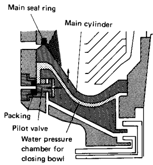
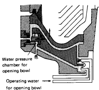
The exact pressure chambers and flow paths vary by model.
16. Operating-water solenoid valves
The solenoid valves are electrically controlled water valves.
They may control:
- Opening bowl, total discharge
- Opening bowl, partial discharge
- Closing bowl
- Sealing water
- Replacement water
- Operating-water tank
The automatic control panel sends signals to operate these valves in the programmed sequence.
Solenoid-valve fault symptoms
| Fault | Possible result |
|---|---|
| Valve fails closed | No bowl opening, no sealing water, or no discharge |
| Valve fails open | Continuous water flow, leakage, or unexpected bowl movement |
| Slow operation | Incomplete discharge or delayed closure |
| Blocked pilot passage | Incorrect hydraulic sequence |
| Electrical fault | No automatic discharge command |
Check electrical signal, valve movement, water pressure, and the downstream passage.
17. Discharge confirmation
Automatic control should be verified by actual machine response.
Possible confirmation signs:
- Short discharge sound
- Current increase or change
- Discharge detector response
- Water or sludge flow to the drain
- Control-panel indication
- Return of pressure after discharge
- Normal bowl-closing response
The Multi-Monitor discharge detector can indicate whether discharge has occurred, depending on the installed model.
No-discharge condition
A no-discharge indication may mean:
- Bowl did not open.
- Operating-water pressure was low.
- Solenoid valve failed.
- Discharge port was blocked.
- Sludge was packed.
- Detector or proximity signal failed.
- Timer setting was incorrect.
Do not assume that the timer command proves physical discharge.
18. Manual sludge discharge during operation
A manual discharge may be required while the purifier is feeding.
The Mitsubishi procedure instructs the operator to:
- Press the STOP FEEDING control.
- Stop oil feed to the purifier.
- Perform the specified discharge steps.
- Complete the closing and sealing sequence.
- Resume feed according to the procedure.
Do not manually open plugs or access parts during a sludge-discharge process. The manual warns against opening the sludge-outlet plug during discharge.
19. Safety during discharge
During discharge:
- The bowl remains a high-speed rotating machine.
- Sludge and water may leave at high velocity.
- Oil may be hot.
- Operating-water pressure is present.
- Automatic valves may move without further warning.
Never:
- Open the frame cover during rotation.
- Open a sludge plug during discharge.
- Put hands near discharge ports.
- Bypass an interlock casually.
- Resume feed before the bowl is closed and sealed.
- Stand over an unprotected sludge outlet.
20. Fault: incomplete de-sludging
Symptoms
- Sludge remains after discharge.
- Vibration increases after several cycles.
- Clean-oil quality deteriorates.
- Discharge quantity is less than expected.
- No-discharge alarm appears.
Possible causes
- Low operating-water pressure
- Insufficient opening-water time
- Blocked discharge ports
- Sludge too dense or packed
- Incorrect timer settings
- Insufficient disc-stack pressure
- Too few discs or deformed discs
- Bowl closing too early
- Faulty solenoid or pilot valve
The troubleshooting material identifies low or insufficient disc-stack pressure, too few discs, deformed discs, and early bowl closing as possible causes of incomplete de-sludging.
21. Fault: bowl does not open
Check:
- Operating-water pressure.
- Opening-water solenoid valve.
- Closing-water chamber.
- Pilot valves.
- Water strainers and passages.
- Timer command.
- Sliding bowl mechanism.
- Sludge packed around the moving part.
- Drain passages.
The Mitsubishi troubleshooting procedure recommends cleaning the bowl and operating-water equipment and raising operating-water pressure when the bowl cannot open.
22. Fault: bowl closes too early
Possible causes:
- Closing-water timer too long or incorrectly sequenced.
- Opening-water supply interrupted.
- Solenoid valve sticking.
- Incorrect pressure.
- Control-panel timing fault.
- Sludge pressed into the gasket.
Consequences:
- Incomplete discharge
- Gasket wear
- Sludge remaining in the bowl
- Repeated no-discharge alarms
23. Fault: excess oil loss during discharge
Possible causes:
- Total discharge used when partial discharge was suitable.
- Feed not stopped before opening.
- Discharge timing too long.
- Bowl not correctly closed before feed.
- Incorrect water sequence.
- Excessive opening-water quantity.
- Wrong operating mode selected.
Corrective direction:
- Confirm the purifier’s discharge type.
- Confirm feed-valve sequence.
- Check timers and solenoid operation.
- Confirm bowl closure and seal restoration.
24. Fault: repeated water-detector operation
Possible causes:
- High water load.
- Incorrect interface.
- Excessive feed rate.
- Wrong gravity disc.
- Water outlet restriction.
- Incorrect sealing or replacement water.
- Water-detector pressure-line issue.
The G-HIDENS Water Detector monitors changing separated-water levels through a pressure sensor in the circulation line.
25. Discharge process diagram
Interpret the timing diagram as a sequence of states:
The diagram also distinguishes timer-controlled periods for:
- Feed interval
- Opening-water supply
- Discharge
- Closing bowl
- Sealing water
- Replacement water
- Intermittent water supply
26. Discharge interval decision
Use this logic:
The timer should not be adjusted blindly. A change in interval may indicate:
- New fuel batch
- Engine operating change
- Increased water ingress
- Filter or tank problem
- Purifier deterioration
27. Operator checklist for sludge discharge
Before discharge
- [ ] Purifier is at normal speed.
- [ ] Discharge command is correct for the purifier type.
- [ ] Feed is stopped or diverted as required.
- [ ] Automatic control is in the correct mode.
- [ ] Discharge outlet is open and safe.
- [ ] Operating-water pressure is normal.
- [ ] No personnel are near the sludge outlet.
During discharge
- [ ] Opening-water valve operates.
- [ ] Expected discharge sound occurs.
- [ ] Current or detector response confirms discharge.
- [ ] No abnormal vibration occurs.
- [ ] No uncontrolled leakage occurs.
- [ ] No plug or cover is opened.
After discharge
- [ ] Bowl closes fully.
- [ ] Sealing or replacement water is supplied.
- [ ] Water seal is restored.
- [ ] Feed resumes only after the correct sequence.
- [ ] Light-liquid pressure returns to normal.
- [ ] No oil appears at the water or sludge outlet.
- [ ] Vibration and current are normal.
- [ ] Event is recorded in the log.
28. Revision questions with answers
Question 1
Why must sludge be discharged?
Answer: To restore bowl capacity, maintain separation efficiency, prevent imbalance, and avoid blocked passages.
Question 2
What is a self-cleaning purifier?
Answer: A purifier that uses operating water to open and close the bowl and remove sludge without routine dismantling.
Question 3
What is total discharge?
Answer: Discharge of the total or substantially total contents of the bowl.
Question 4
What is partial discharge?
Answer: Discharge mainly of separated water and solids while retaining most of the treated oil.
Question 5
What does opening water do?
Answer: It moves the main cylinder or sliding bowl bottom to open the discharge ports.
Question 6
What does closing water do?
Answer: It moves the bowl mechanism back to the sealed position.
Question 7
What is sealing water used for after discharge?
Answer: To restore the heavy-liquid region and prevent oil from escaping through the water outlet.
Question 8
Why are timer settings important?
Answer: They control valve operation, opening time, discharge time, closing, sealing, replacement water, and feed restart.
Question 9
What confirms that discharge actually occurred?
Answer: Current change, discharge sound, detector response, visible sludge/water flow, and return to normal pressure.
Question 10
What causes incomplete de-sludging?
Answer: Low water pressure, blocked ports, short opening time, packed sludge, poor disc pressure, deformed discs, or early closing.
Question 11
When is washing water used?
Answer: In the referenced Selfjector arrangement, washing water is used for lubricating-oil purifier bowl cleaning, not the fuel-oil purifier arrangement.
Question 12
What must be done before manual discharge during feeding?
Answer: Stop or divert the oil feed according to the manufacturer’s procedure before performing discharge.
29. Self-test sequence exercise
Put these events in the correct order:
- Supply closing water
- Stop or divert oil feed
- Resume oil feed
- Supply opening water
- Confirm discharge
- Establish sealing water
- Normal purification
- Sludge leaves bowl
Correct order: