
Purifier Bowl Construction and Disc-Stack Assembly
How is the purifier bowl built, and why is the disc stack assembled so precisely?
Key Principles at a Glance 7 points
- The bowl is a precision high-speed assembly: body, hood, bowl nut, distributor, disc stack, top disc and sliding bottom are matched parts, not interchangeable ones.
- Discs are stacked in a specific order and orientation; a wrong disc, a wrong order or a missing disc changes the flow path and ruins separation.
- The bowl nut compresses the disc stack so the discs stay evenly spaced and the stack cannot move at speed.
- Bowl parts are individually balanced and carry tally marks — they must go back in their original relative positions or the bowl will vibrate.
- Disc defects such as deformation, corrosion, clogged holes or a wrong disc count directly reduce separation efficiency.
- Cleanliness and correct O-ring and seal seating during assembly decide whether the bowl will seal and discharge correctly.
- A purifier bowl carries a gravity disc and a sliding bottom; a clarifier bowl does not.
1. Learning objectives
Course position: Topic 5 of the purifier learning sequence
Main question: How is the purifier bowl built, and why is the disc stack assembled so precisely?
After studying this lesson, you should be able to:
- Describe the construction of a purifier bowl.
- Identify the bowl body, bowl hood, bowl nut, distributor, discs, top disc, and sealing elements.
- Explain how the disc stack forms the separation chamber.
- Explain why disc compression and the correct number of discs matter.
- Describe the role of different disc sizes and distance pieces.
- Explain why bowl balance and tally-mark alignment are safety-critical.
- Describe the safe logic of bowl dismantling and assembly.
- Identify common disc and bowl defects.
- Explain how poor disc assembly causes poor separation and vibration.
- Read the manufacturer’s bowl-part and dismantling graphics.
2. Why bowl construction matters
The purifier bowl is both:
- A high-speed rotating mechanical assembly, and
- A precision hydraulic separation chamber.
It must perform several jobs simultaneously:
- Rotate safely at operating speed.
- Hold the disc stack under the correct compression.
- Maintain separate oil and water flow paths.
- Collect solids at the outer bowl wall.
- Discharge sludge without dismantling the bowl.
- Maintain seals under hydraulic pressure.
- Remain dynamically balanced.
A small assembly error can therefore produce two types of failure at once:
- Separation failure: water, oil, or solids go to the wrong location.
- Mechanical failure: vibration, rubbing, seal damage, or bowl damage occurs.
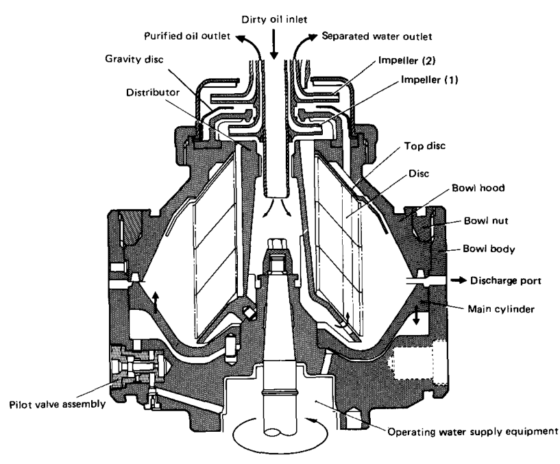
The Mitsubishi manual describes the bowl as a container formed by the bowl body, bowl hood, and bowl nut. Inside it are the disc-and-top-disc separation chamber and the distributor. A hydraulically operated main cylinder discharges solids accumulated on the bowl wall.
3. Bowl construction overview
The actual configuration varies by model, but the construction logic is consistent:
- The bowl body forms the lower rotating container.
- The bowl hood closes the upper region.
- The bowl nut clamps the assembly.
- The distributor introduces feed liquid.
- The disc stack provides the separation passages.
- The top disc defines the upper liquid arrangement.
- The main cylinder or sliding bowl bottom controls sludge discharge.
4. Bowl body
The bowl body is the main lower rotating section.
4.1 Functions
The bowl body:
- Supports the internal rotating components.
- Forms the outside wall of the separation chamber.
- Receives solids thrown outward by centrifugal force.
- Contains hydraulic passages for bowl opening and closing.
- Provides the location for pilot valves and discharge mechanisms.
- Transfers rotation from the spindle to the bowl assembly.
4.2 Sludge collection
During operation, solids move outward and collect against the inside wall of the bowl body.
The wall must remain sound and correctly shaped. Corrosion, erosion, or impact damage can affect:
- Bowl strength
- Sludge capacity
- Hydraulic sealing
- Balance
- Safe rotation
4.3 Main-cylinder location
The main cylinder or sliding bowl mechanism is fitted in the bowl body. It moves hydraulically to open and close the sludge-discharge path.
If the cylinder does not move correctly:
- Sludge remains in the bowl.
- Separation area decreases.
- The bowl can become unbalanced.
- Gaskets may be damaged.
- Discharge cycles may fail.
5. Bowl hood
The bowl hood forms the upper part of the rotating bowl.
5.1 Functions
The bowl hood:
- Encloses the disc stack.
- Forms the upper boundary of the separation chamber.
- Supports the top-disc and outlet arrangement.
- Contains or locates sealing surfaces.
- Helps maintain the correct internal flow geometry.
5.2 Seal surface
The main seal ring is installed beneath the bowl hood. During dismantling, the manufacturer warns that the seal surface must not be damaged.
A damaged bowl-hood seal surface can cause:
- Internal oil leakage
- Operating-water leakage
- Loss of hydraulic pressure
- Water and oil mixing
- Failure of bowl closing
5.3 Removing the bowl hood
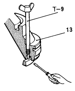
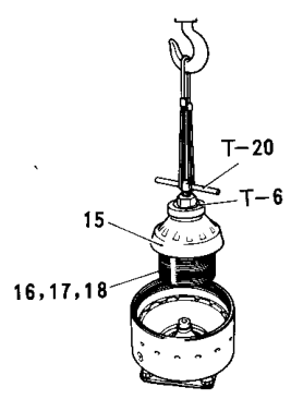
The manual uses a jack and specified tool holes to lift the bowl hood. Do not force the hood with improvised tools because this can damage:
- The bowl hood
- The top disc
- The main seal ring
- The disc stack
- The bowl body
6. Bowl nut
The bowl nut clamps the bowl assembly together.
6.1 What the bowl nut maintains
Correct bowl-nut tightening maintains:
- Disc-stack compression
- Top-disc seating
- Bowl-hood seating
- Seal compression
- Internal hydraulic geometry
- Mechanical integrity at high speed
6.2 Why direct removal is unsafe for the bowl
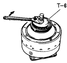
The manufacturer instructs the operator to install a disc clamp plate before removing the bowl nut. The clamp compresses the discs and prevents excessive force from being transferred to the bowl hood.
If the bowl nut is removed directly:
- The disc stack can release unevenly.
- Excessive force can reach the bowl hood.
- The hood may be damaged.
- The assembly may shift or become difficult to control.
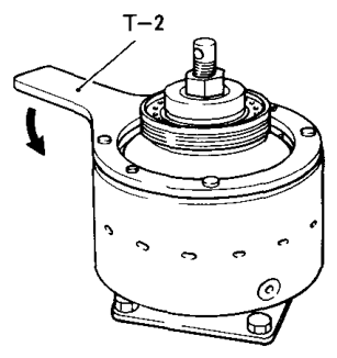
6.3 Bowl-nut tightening
The bowl nut must be tightened using the manufacturer’s specified method. The operator must not substitute:
- An unknown torque value
- An improvised hammering method
- A different nut or clamp
- A missing disc
- A damaged thread
The bowl nut is part of a balanced rotating assembly, not an ordinary stationary cover.
7. Distributor construction
The distributor sits below or within the disc stack and receives dirty oil from the inlet.
7.1 Main functions
The distributor:
- Receives dirty oil.
- Spreads the oil to the separation chamber.
- Accelerates the oil toward bowl speed.
- Feeds the correct radial region of the discs.
- Supports or locates the disc assembly in many designs.
Reed’s explains that radial distributor vanes rapidly bring the oil up to bowl speed before the oil enters the disc passages.
7.2 Distributor and disc mounting
The discs are mounted on or located by the distributor. They must be:
- Correctly oriented
- Correctly ordered
- Fully seated
- Properly compressed
- Free from damaged keys and splines
A disc that is not pressed correctly onto the distributor can damage its key groove. The maintenance instructions identify key-groove deformation, especially among upper discs, as a problem associated with poor disc setting.
8. Disc stack construction
The disc stack is a set of thin conical discs arranged closely together.
The drawing is conceptual. Exact disc profiles and spacing depend on the purifier model.
8.1 Why many discs are used
A single open bowl gives particles a relatively long settling distance. Multiple discs divide the chamber into many thin passages.
This provides:
- Shorter settling distances
- More separation surface
- Better movement of solids toward disc surfaces
- More controlled liquid flow
- Greater effective separation capacity
Reed’s describes conical discs as reducing the settling distance in a large-diameter bowl centrifuge.
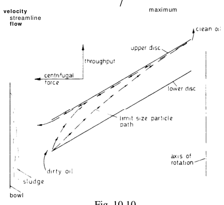
8.2 Flow through the stack
In purifier operation:
- Feed enters the outer region of the disc stack.
- Water and solids move outward.
- Oil moves inward between the discs.
- Solids reach disc surfaces and migrate to the sludge space.
- Water passes toward the heavy-liquid region.
- Clean oil reaches the light-liquid outlet.
9. Different disc forms in the stack
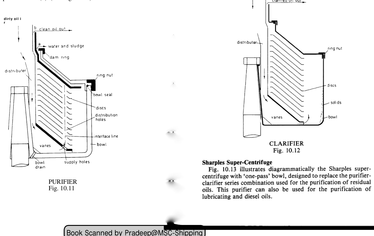
The Mitsubishi dismantling instructions identify different disc arrangements.
9.1 Main discs
The main discs form most of the separation stack. They establish the closely spaced passages through which the oil flows.
9.2 Smaller-diameter discs
The manual states that discs with smaller diameter are installed in the lower part of the disc set for certain models.
Their purpose is to match the internal flow geometry at the lower part of the bowl and provide the correct transition from distributor flow into the main separation region.
9.3 Discs with distance pieces
The lowermost disc may include distance pieces on the inside and outside.
These pieces help maintain:
- Correct axial spacing
- Correct lower flow passage
- Stable support of the disc stack
- Correct location relative to the distributor and bowl body
9.4 Model-specific arrangements
Not every purifier model uses exactly the same disc set. The manual notes that some disc arrangements differ by model.
Therefore:
Never transfer a disc arrangement from one purifier model to another without checking the maker’s drawing.
10. Disc stack compression
The disc stack must be compressed so the discs remain in their designed positions during rotation.
10.1 Compression purpose
Compression prevents:
- Axial movement
- Gaps between discs
- Uneven flow distribution
- Disc vibration
- Mechanical rubbing
- Unbalance
10.2 Loss of elasticity
The Mitsubishi maintenance instructions explain that disc sets can lose elasticity. Discs that were not initially in close contact can settle under bowl-nut tightening and centrifugal force, creating a gap between the top disc and the disc set. This worsens separation and can cause unbalance.
The corrective action is model-specific and may require adding the proper spare or compensating disc according to the manufacturer’s figure.
10.3 Too many or too few discs
Incorrect disc count changes:
- Stack height
- Compression
- Separation passage geometry
- Outlet flow
- Bowl balance
A missing disc is not a minor omission. It changes the purifier’s hydraulic and mechanical condition.
11. Disc defects
11.1 Cracks
Cracked discs must be replaced. The maintenance material specifically states that cracked discs must not be repaired by welding.
11.2 Deformation
Deformed discs can:
- Touch adjacent discs
- Reduce passage area
- Disturb flow
- Create local pressure losses
- Produce unbalance
11.3 Damaged key grooves
A deformed key groove can allow disc movement or incorrect seating on the distributor.
11.4 Torn edges
A torn disc edge may be repaired only according to the maker’s permitted method if the original shape and thickness can be preserved. If the damage produces a crack, replacement is required.
11.5 Deposits
Hardened sludge on discs:
- Reduces passage area
- Increases resistance
- Changes liquid distribution
- Reduces effective separation area
- Makes the bowl unbalanced
12. Top disc and disc-stack relationship
The top disc closes and defines the upper end of the main disc stack.
It must be correctly located relative to:
- The bowl hood
- The main seal ring
- The light-liquid chamber
- The heavy-liquid path
- The gravity-disc and outlet arrangement
A gap between the top disc and the main stack can produce:
- Internal bypass flow
- Poor separation
- Interface instability
- Unbalance
- Outlet contamination
The top disc is therefore both a hydraulic boundary and a mechanical compression reference.
13. Bowl seals and O-rings
Bowl construction includes many seals:
- Main seal ring
- O-rings
- Seat packing
- Valve-seat seals
- Chamber packing
- Outlet seals
13.1 Purpose
Seals separate:
- Oil from water
- Oil from operating water
- Operating water from the drain
- Internal chambers from the frame
13.2 Correct installation
During assembly:
- Clean grooves.
- Inspect sealing surfaces.
- Lubricate only with the approved lubricant.
- Do not twist O-rings.
- Do not pinch seals during insertion.
- Do not reuse damaged or hardened seals.
- Confirm the seal is fully seated.
The assembly instructions specifically caution against twisting O-rings and recommend lubrication of relevant sliding and operating-water parts.
13.3 Seal failure symptoms
- Oil leaking from the bowl
- Water mixing with oil
- Bowl unable to close
- Bowl opening after a long delay
- Loss of operating-water pressure
- Sludge pressed into a gasket
14. Bowl balance and tally marks
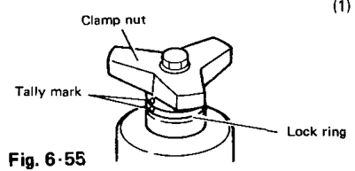
The bowl is dynamically balanced. During assembly, matching marks must be aligned.
The manual instructs operators to align the tally marks of the bowl nut and heavy-liquid chamber with the tally mark on the bowl body to prevent unbalance.
If parts are assembled in the wrong angular relationship:
- Mass distribution changes.
- Vibration increases.
- Bearings are loaded unevenly.
- The bowl may rub or fail.
Balance rule
Never treat bowl-part orientation as cosmetic. It is a rotating-balance requirement.
15. Bowl removal from the frame
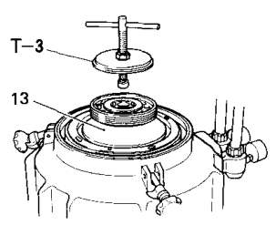
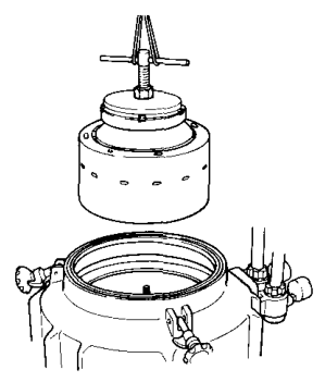
The bowl is removed vertically using the manufacturer’s jack, lifting arrangement, and dismantling stand.
The manual shows:
- Installing the jack.
- Lifting the bowl.
- Drawing it out vertically.
- Placing it on a dismantling stand.
- Ensuring the stand pins enter the correct bowl-body holes.
Safety requirements
Before lifting:
- Stop and isolate electrical power.
- Confirm the bowl has stopped completely.
- Secure the lifting equipment.
- Keep personnel clear of the suspended load.
- Use the correct dismantling stand.
- Do not support the bowl on vulnerable seal or outlet surfaces.
16. Disc-stack removal sequence
A simplified learning sequence is:
- Stop and isolate the purifier.
- Remove the frame cover using the maker’s method.
- Remove or draw out the gravity-disc and heavy-liquid arrangement as required.
- Install the disc clamp plate.
- Compress the disc stack.
- Remove the bowl nut.
- Remove the bowl hood and top disc using the specified tool.
- Lift the disc set using the distributor and approved handle.
- Keep discs in order.
- Inspect, clean, and record defects.
The actual sequence must follow the installed purifier’s operation manual.
17. Disc-stack cleaning
Cleaning is required because the disc passages are narrow and contamination reduces their effective area.
17.1 Cleaning objectives
Remove:
- Sludge
- Asphaltic deposits
- Rust particles
- Catalyst fines
- Carbonaceous deposits
- Hardened oil
17.2 Cleaning precautions
- Use an approved cleaning method.
- Do not scratch disc surfaces.
- Do not bend discs.
- Do not use excessive force on edges.
- Do not weld damaged discs.
- Dry parts before reassembly.
- Keep different disc types in their correct order.
17.3 Why cleanliness matters
Deposits also create uneven mass distribution, which may cause vibration.
18. Bowl assembly sequence
A simplified assembly logic is:
Assembly checks
Before returning to service:
- Correct disc count
- Correct disc order
- Correct disc orientation
- Correct top-disc position
- Correct gravity-disc size
- Correct seal installation
- Correct tally-mark alignment
- Correct bowl-nut tightening
- Correct outlet impeller installation
- Correct free movement of the sliding bowl mechanism
- No tools or foreign material left inside
19. Why disc order matters
Different discs may have different:
- Diameters
- Internal holes
- External profiles
- Distance pieces
- Key arrangements
- Flow openings
If a disc is placed in the wrong position:
- Feed distribution can change.
- The lower transition can be blocked.
- The disc stack may not compress correctly.
- Separation efficiency can decrease.
- The bowl may become unbalanced.
The Mitsubishi manual specifically notes that small-diameter discs are fitted in the lower part for applicable models and that the lowermost disc can include distance pieces.
20. Construction relationship to separation
Every construction feature has a separation reason.
| Construction feature | Separation purpose |
|---|---|
| Distributor vanes | Accelerate and distribute feed |
| Conical discs | Reduce settling distance |
| Disc spacing | Create thin controlled passages |
| Top disc | Define upper liquid regions |
| Bowl wall | Collect solids |
| Gravity-disc seat | Control heavy-liquid outlet radius |
| Light-liquid chamber | Collect clean oil |
| Heavy-liquid chamber | Collect separated water |
| Bowl seals | Prevent internal bypass |
| Sliding bowl bottom | Remove accumulated sludge |
| Bowl nut | Maintain disc compression |
| Tally marks | Maintain rotating balance |
22. Purifier versus clarifier construction
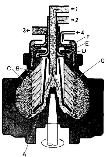
The same basic bowl can be arranged differently for clarifier operation.
Purifier arrangement
- Disc stack separates oil, water, and solids.
- Sealing water establishes the liquid seal.
- Gravity disc controls the heavy-liquid side.
- Heavy-liquid outlet discharges water.
Clarifier arrangement
- Disc stack separates oil and solids.
- Sealing water is not supplied in the same way.
- The water-separation path is not used as in purifier operation.
- The light liquid leaves through the clarifier arrangement.
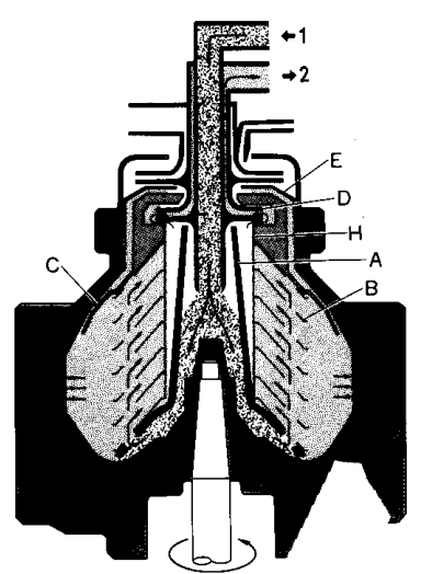
The construction must match the intended operating mode.
23. Revision questions with answers
Question 1
What are the principal parts forming the bowl container?
Answer: Bowl body, bowl hood, and bowl nut.
Question 2
Why is the bowl nut important?
Answer: It clamps the bowl and maintains disc compression, sealing, and mechanical integrity.
Question 3
What is the purpose of the distributor?
Answer: It receives dirty oil, accelerates it toward bowl speed, and distributes it to the disc stack.
Question 4
Why are conical discs used?
Answer: They reduce the settling distance and provide controlled separation passages.
Question 5
What happens if the disc stack is not compressed correctly?
Answer: Gaps, poor separation, disc movement, and unbalance may occur.
Question 6
Why must disc order be preserved?
Answer: Different discs may have different diameters, holes, and distance pieces that match specific positions in the bowl.
Question 7
Why must cracked discs be replaced rather than welded?
Answer: A crack compromises a high-speed rotating component, and welding may not restore its strength or balance.
Question 8
What is the purpose of the top disc?
Answer: It defines the upper separation and outlet regions and helps direct the heavy-liquid flow.
Question 9
What causes a disc-stack gap?
Answer: Loss of disc-set elasticity, insufficient compression, or an incorrect number of discs.
Question 10
Why are tally marks aligned during assembly?
Answer: To preserve the bowl’s designed mass balance and prevent vibration.
Question 11
What can happen if the bowl hood seal is damaged?
Answer: Oil or operating-water leakage, internal bypass, pressure loss, and poor separation.
Question 12
What part opens the bowl during sludge discharge?
Answer: The hydraulically operated sliding bowl bottom or main cylinder.
24. Self-test drawing exercise
Draw the bowl in five layers:
- Bowl body and sludge space
- Distributor
- Disc stack
- Top disc and bowl hood
- Bowl nut and outlet chambers
Then label:
- Feed inlet
- Clean-oil path
- Water path
- Solid-particle path
- Main seal ring
- Gravity disc
- Light-liquid chamber
- Heavy-liquid chamber
- Sliding bowl bottom
- Discharge ports
Finally answer:
- Which parts rotate?
- Which parts form the separation chamber?
- Which part controls disc compression?
- Which part introduces feed oil?
- Which parts define the liquid outlets?
- Which part removes sludge?
- Which marks preserve balance?
25. Assembly inspection checklist
Before starting the purifier after bowl assembly, confirm:
- [ ] Bowl body is clean and undamaged.
- [ ] Bowl hood is correctly seated.
- [ ] Main seal ring is undamaged.
- [ ] All O-rings are correctly installed and untwisted.
- [ ] Distributor is correctly fitted.
- [ ] Disc types and order match the manual.
- [ ] Disc count is correct.
- [ ] Disc stack is compressed correctly.
- [ ] Top disc is seated.
- [ ] Bowl nut is correctly tightened.
- [ ] Gravity disc matches the oil condition.
- [ ] Light-liquid impeller is correctly fitted.
- [ ] Heavy-liquid impeller is correctly fitted.
- [ ] Tally marks are aligned.
- [ ] Sliding bowl mechanism moves correctly.
- [ ] Operating-water passages are clear.
- [ ] No foreign material remains inside.
- [ ] Bowl rotates freely by the maker’s permitted check.
- [ ] Frame cover is correctly installed and locked.