
Purifier Troubleshooting and Fault Diagnosis
How can purifier symptoms be converted into safe, logical fault diagnosis?
Key Principles at a Glance 8 points
- Troubleshoot from symptoms and recorded data rather than guesses — record speed, current, temperatures, pressures, discharge behaviour and oil quality before changing anything.
- Safety comes before diagnosis: isolate and stop the machine before investigating anything mechanical.
- Faults fall into a few families — oil leaving by the wrong outlet, water carry-over, discharge faults, drive faults and control faults — and each family has a short list of likely causes.
- Oil-to-wrong-outlet faults are almost always an interface problem: wrong gravity disc, wrong feed rate, wrong treating temperature or a failed water seal.
- Discharge faults point at the operating-water system: insufficient operating water, low air pressure, a stuck pilot valve or a wrong timer setting.
- Drive faults such as low speed, overload, high vibration and abnormal sound point at the motor, the bowl assembly or the gearing.
- A fault appearing immediately after an overhaul is compared first with what was assembled or set during that overhaul.
- Never adjust settings blindly: change one thing, observe the result, and record it.
1. Learning objectives
Course position: Topic 14 of the purifier learning sequence
Main question: How can purifier symptoms be converted into safe, logical fault diagnosis?
After studying this lesson, you should be able to:
- Troubleshoot from symptoms rather than guesses.
- Separate process faults from mechanical faults.
- Diagnose oil and water flowing to the wrong outlet.
- Diagnose water in purified oil.
- Diagnose a bowl that will not open or close.
- Diagnose incomplete sludge discharge.
- Diagnose low feed rate and high motor current.
- Diagnose vibration and abnormal sound.
- Use temperature, gravity disc, pressure, speed, and flow checks correctly.
- Decide when to stop immediately.
- Build a logical troubleshooting tree.
- Answer an examination question on purifier faults.
2. The troubleshooting rule
A purifier fault should be diagnosed in this order:
Do not start by dismantling the bowl for every fault.
Do not continue operation to collect more evidence when the symptom is dangerous vibration, contact sound, or a severe leak.
3. Safety before diagnosis
Stop immediately if there is
- Excessive vibration
- Contact or rubbing sound
- Abnormal bearing sound
- Sudden current rise
- Oil escaping from an unsafe location
- Uncontrolled water or oil discharge
- Failure of a critical safety device
- Smoke, burning smell, or electrical fault
The Mitsubishi manual instructs that excessive vibration requires immediate stopping.
Before inspection
- Stop feed.
- Stop the purifier safely.
- Confirm zero bowl speed.
- Switch off and isolate the starter.
- Isolate operating water if required.
- Release pressure safely.
- Do not open the machine while the bowl is rotating.
4. Fault-classification map
| Symptom group | Main systems to examine |
|---|---|
| Oil to heavy-liquid outlet | Seal, gravity disc, temperature, interface, pressure |
| Oil to sludge outlet | Bowl closure, main seal, pilot valve, operating water |
| Water in oil | Sealing/replacement water, interface, bowl closure |
| Bowl will not open | Operating-water pressure, timer, passages, sludge blockage |
| Incomplete discharge | Interval, discharge quantity, opening time, ports, solenoid |
| Low feed rate | Pump, strainer, air leak, relief valve, speed |
| High current | Feed resistance, mechanical drag, friction clutch, bearing |
| Vibration | Sludge imbalance, disc stack, bowl damage, shaft, foundation |
| Abnormal sound | Bearing, gear, rubbing, loose part, friction clutch |
| No rated speed | Friction clutch, motor, overload, mechanical drag |
5. Data to record before changing settings
Record:
- Oil type
- Feed temperature
- Feed rate
- Oil specific gravity or density
- Water content
- Current
- Bowl speed
- Light-liquid pressure
- Heavy-liquid pressure
- Operating-water pressure
- Air pressure
- Discharge interval
- Discharge sound
- Vibration level
- Alarm code
- Valve positions
- Gravity-disc size
- Recent maintenance or changeover
A fault that appears immediately after overhaul should first be compared with assembly and setting changes.
6. Troubleshooting process flow
7. Fault 1 — Oil flows to the heavy-liquid outlet
Symptom
Oil appears at the water or heavy-liquid outlet instead of remaining in the light-liquid outlet.
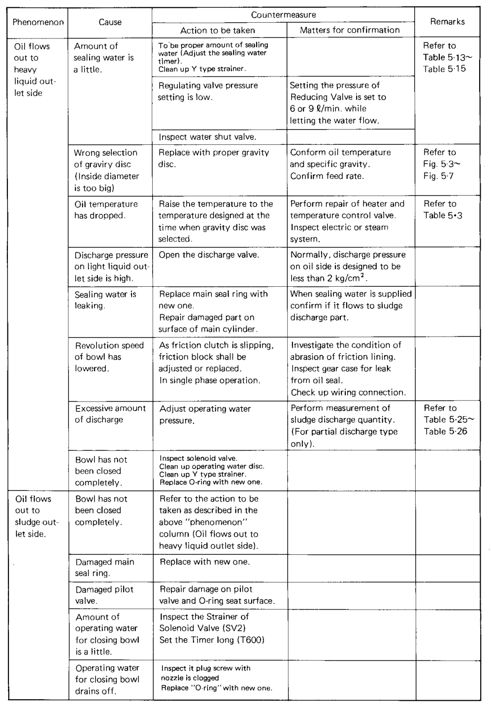
Likely causes
- Insufficient sealing water
- Wrong gravity disc
- Gravity-disc inside diameter too large
- Oil temperature too low
- Heavy-liquid outlet pressure too high
- Sealing-water leakage
- Bowl speed reduced
- Interface displaced outward
Diagnosis sequence
- Confirm actual oil temperature.
- Confirm feed rate.
- Check oil specific gravity or density.
- Verify gravity-disc selection.
- Check sealing-water quantity and timing.
- Inspect sealing-water strainer and valve.
- Check heavy-liquid outlet pressure.
- Confirm bowl speed and current.
- Inspect for bowl or seal faults if external checks are normal.
Explanation
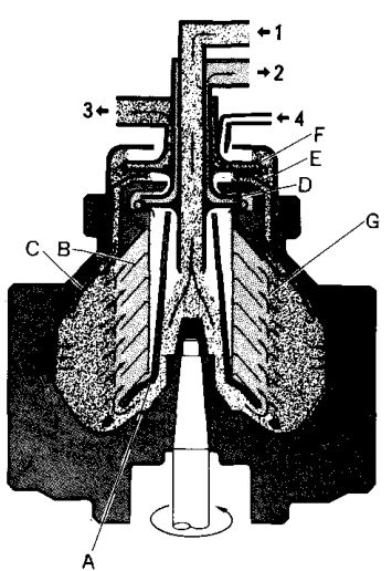
A large gravity-disc inside diameter moves the interface outward. If the interface moves too far, oil can reach the heavy-liquid outlet.
The maker explains that gravity-disc selection is one of the most important adjustments in purifier operation.
8. Gravity-disc diagnosis
The gravity disc controls the radial position of the interface between light liquid and heavy liquid.
If oil goes to the heavy-liquid side
The interface may be too far outward. Possible responses include:
- Select a smaller correct gravity disc.
- Confirm oil temperature and specific gravity.
- Confirm feed rate and outlet pressure.
- Confirm a proper water seal.
Do not select a disc from memory alone. Use the maker’s chart for the actual oil, temperature, and throughput.
If water goes to the light-liquid side
The interface may be too far inward. Possible responses include:
- Select a larger correct gravity disc.
- Confirm water seal and feed conditions.
- Check heavy-liquid discharge pressure.
- Confirm the bowl is operating at rated speed.
9. Fault 2 — Oil flows to the sludge outlet
Likely causes
- Bowl has not closed completely.
- Main seal ring is damaged.
- Main cylinder sealing surface is damaged.
- Pilot valve is damaged or leaking.
- Closing-water quantity is insufficient.
- Operating water drains away.
- Excessive discharge occurred.
- Bowl speed is low.
- Friction clutch is slipping.
Diagnosis
- Stop feed if oil loss is significant.
- Confirm the bowl-closing sequence.
- Check discharge sound and current change.
- Check closing-water pressure and timer.
- Inspect the main seal ring.
- Inspect main-cylinder sealing surface.
- Inspect pilot valve and O-ring seat.
- Check the operating-water strainer.
- Check gear case for leakage and friction-clutch condition.
The troubleshooting table specifically links oil at the sludge outlet with incomplete bowl closure, damaged sealing components, and hydraulic faults.
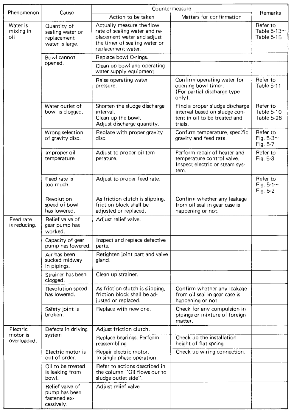
10. Fault 3 — Water is mixed with purified oil
Likely causes
- Sealing-water quantity too high
- Replacement-water quantity too high
- Interface positioned incorrectly
- Bowl not fully closed
- Gravity-disc selection incorrect
- Oil temperature incorrect
- Excess feed rate
- Damaged O-ring or main seal
- Heavy-liquid outlet pressure abnormal
Diagnosis sequence
The manual recommends actually measuring sealing-water and replacement-water flow rather than assuming the timer setting is correct.
Immediate checks
- Stop or divert contaminated oil.
- Confirm clean-oil outlet condition.
- Check the water detector.
- Verify sealing-water timer.
- Check for water flowing during the wrong sequence.
11. Fault 4 — Bowl will not open
Symptom
A discharge command occurs, but no discharge sound, current change, or sludge movement is observed.
Likely causes
- Operating-water pressure too low
- Opening-water valve not operating
- Opening timer too short
- Operating-water strainer clogged
- Water passage blocked by scale or sludge
- Bowl discharge port blocked
- Main cylinder seal damaged
- Pilot valve not switching
- Control wiring or solenoid fault
- Sludge compacted in the bowl
Diagnosis sequence
- Confirm the discharge command reached the control panel.
- Confirm solenoid operation.
- Check operating-water pressure.
- Inspect the strainer.
- Check opening-water quantity and timer.
- Confirm water reaches the correct chamber.
- Inspect discharge ports after safe isolation.
- Inspect the main cylinder and pilot valve.
Do not repeatedly force a discharge cycle without finding why the bowl does not open.
12. Fault 5 — Bowl opens but closes too early
Symptoms
- Incomplete sludge discharge
- Sludge remains in the bowl
- Discharge is small or weak
- Vibration returns soon after discharge
Causes
- Closing-water timer too long or incorrectly sequenced
- Insufficient opening-water quantity
- Restricted operating-water passage
- Solenoid valve leakage
- Pilot-valve fault
- Main-cylinder friction or seal damage
- Control timer error
Corrective checks
- Confirm the opening duration.
- Confirm discharge quantity.
- Inspect solenoid valves and strainers.
- Confirm operating-water pressure during the cycle.
- Check that the bowl remains open long enough.
- Clean the bowl and ports.
13. Fault 6 — Incomplete sludge discharge
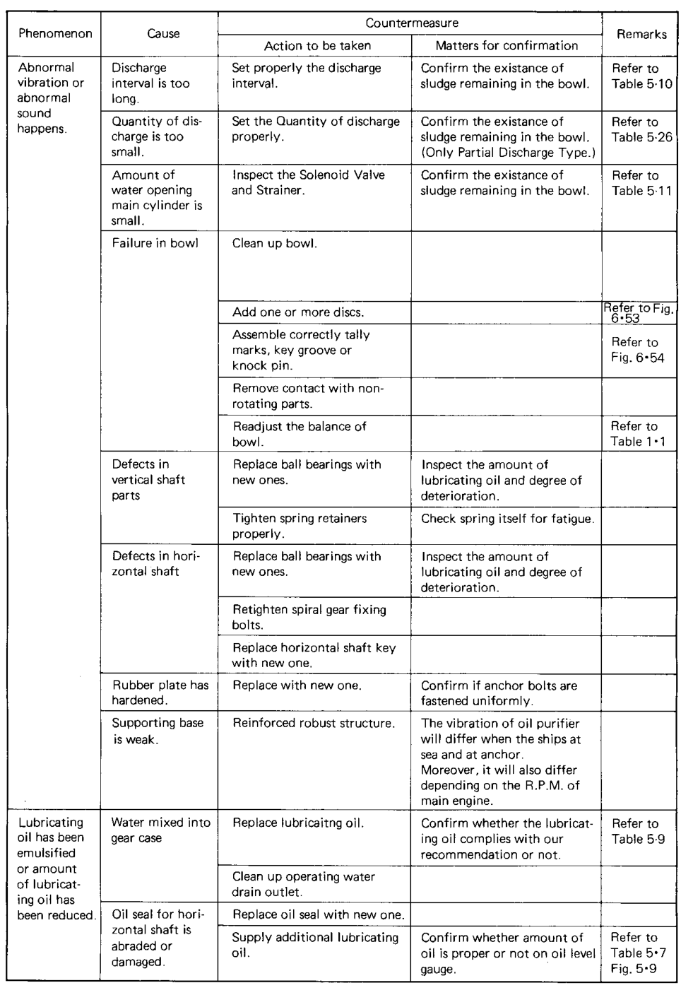
Likely causes
- Discharge interval too long
- Discharge quantity too small
- Bowl does not open fully
- Opening-water quantity too small
- Solenoid valve restricted
- Water strainer clogged
- Sludge ports blocked
- Incorrect disc or bowl assembly
- Sludge too dense or hardened
The troubleshooting table recommends checking the actual sludge remaining in the bowl and adjusting interval or discharge quantity.
Diagnosis
Consequences
- Reduced bowl capacity
- Faster imbalance
- Increasing vibration
- Reduced separation efficiency
- More frequent alarms
- Difficult future discharge
14. Fault 7 — Feed rate is low
Likely causes
- Feed strainer clogged
- Pump capacity reduced
- Relief valve setting incorrect
- Air entering suction piping
- Loose pipe joint or valve gland
- Bowl speed reduced
- Foreign matter in pump or pipe
- Friction clutch slipping
- Motor problem
Diagnosis sequence
- Check tank level and suction valve.
- Check the feed strainer.
- Check pump suction for air leakage.
- Check pressure and relief-valve setting.
- Check pipe joints and valve glands.
- Check bowl speed and current.
- Inspect pump and drive if external checks are satisfactory.
Do not compensate for a restricted feed path by randomly changing purifier settings.
15. Fault 8 — Motor is overloaded
Likely causes
- Mechanical drag
- Bearing damage
- Bowl rubbing stationary parts
- Excessive sludge imbalance
- Feed resistance or pump overload
- Friction clutch fault
- Electrical motor fault
- Incorrect assembly
Immediate action
If current rises abnormally:
- Stop feed.
- Observe vibration and sound.
- Stop the purifier if the rise persists or is dangerous.
- Compare current with the maker’s expected range.
- Inspect mechanical and electrical causes.
The manual links motor overload with driving-system defects and electrical faults.
16. Fault 9 — Bowl speed is low
Causes
- Friction clutch slipping
- Worn friction block
- Motor fault
- Low supply voltage
- Excessive mechanical drag
- Bearing failure
- Gear or shaft fault
- Overloaded pump
Why low speed is serious
Lower speed reduces centrifugal acceleration:
Since acceleration varies with the square of angular speed, even a modest speed reduction can strongly reduce separation performance.
Low speed can also cause:
- Interface instability
- Poor water separation
- Oil to heavy-liquid outlet
- Higher sludge carry-over
- Abnormal discharge behaviour
Do not feed oil at normal throughput when rated speed is not achieved.
17. Fault 10 — Excessive vibration
Immediate response
- Stop feed.
- Stop the purifier immediately if vibration is excessive.
- Do not perform normal sludge discharge if it may increase danger.
- Keep personnel away.
- Confirm complete stop.
- Isolate and investigate.
Possible causes
- Uneven sludge deposition
- Bowl incorrectly assembled
- Parts from different bowls mixed
- Disc-stack pressure relaxed
- Damaged bowl parts
- Missing disc or distance piece
- Shaft or bearing defect
- Weak foundation
- Loose anchor bolts
- Ship vibration
- Gear or horizontal-shaft fault
A troubleshooting reference attributes uneven running to uneven solids deposition, incorrect assembly, relaxed disc-stack pressure, or damaged parts.
Investigation after stop
- Check whether sludge is uneven.
- Check bowl assembly marks.
- Confirm correct disc set.
- Inspect bowl parts for damage.
- Inspect bearings and shaft.
- Check supporting base and anchor bolts.
- Check whether vibration depends on ship or engine speed.
18. Fault 11 — Abnormal sound
Sound classification
| Sound | Possible area |
|---|---|
| Rubbing/contact | Bowl, disc, stationary part |
| Grinding | Bearing or gear |
| Knocking | Loose or damaged rotating part |
| Repeated hydraulic clicking | Solenoid or valve sequence |
| High-pitched slipping | Friction clutch |
| Sudden bearing noise | Bearing failure |
Abnormal sound should not be ignored because high-speed contact can escalate rapidly.
Correct response
- Stop feed.
- Stop the purifier.
- Do not open the bowl until zero speed.
- Isolate power.
- Inspect systematically.
19. Fault 12 — Discharge current or sound is absent
Possible causes
- Discharge command not generated
- Timer fault
- Solenoid valve not energised
- Operating-water pressure low
- Bowl does not open
- Discharge port blocked
- Detector or indication fault
Check
- Automatic panel status
- Timer setting
- Solenoid coil and valve movement
- Strainer
- Operating-water pressure
- Current trace
- Discharge sound
- Actual sludge remaining after safe inspection
Never declare successful discharge from a timer indication alone.
20. Fault 13 — Discharge occurs but detector alarms
Possible causes
- Water leakage through an incorrect path
- Bowl not fully closed
- Main seal damaged
- Pilot-valve leakage
- Incorrect replacement-water timing
- Water detector contamination
- Operating-water drain problem
Diagnosis
Compare:
- Detector signal
- Actual discharge sound
- Current increase
- Water movement
- Bowl closure
- Seal condition
A detector alarm can be caused by a real leakage path or by a sensor/control fault. Confirm both.
21. Fault 14 — Purified-oil pressure is high
Causes
- Outlet valve partly closed
- Downstream restriction
- Back-pressure valve set too high
- Outlet line blocked
- Pump or impeller fault
- Oil too viscous due to low temperature
- Excessive feed rate
Effects
- Interface displacement
- Oil to heavy-liquid outlet
- Motor load increase
- Reduced throughput
- Seal stress
Check downstream restrictions before changing gravity disc.
22. Fault 15 — Oil temperature is incorrect
Low temperature causes
- High viscosity
- Lower flow through the disc stack
- Higher pump load
- Poor separation
- Changed interface conditions
- Possible oil to the wrong outlet
High temperature causes
- Oil degradation
- Seal damage
- Fire hazard
- Unstable viscosity and density
- Unsafe handling condition
Checks
- Heater output
- Temperature-control valve
- Steam or electrical supply
- Sensor calibration
- Insulation
- Actual oil temperature at purifier inlet
The troubleshooting table directs the operator to repair the heater and temperature-control system when temperature is incorrect.
23. Fault 16 — Sealing-water problem
Too little sealing water
May cause oil to move toward the heavy-liquid outlet.
Too much sealing water
May cause water contamination or unstable interface.
Sealing-water leakage
May be caused by:
- Main seal ring
- Main-cylinder surface
- Pilot valve
- O-ring
- Valve seat
- Incorrect timing
Diagnosis
- Measure actual flow.
- Check timer.
- Inspect strainer.
- Confirm pressure.
- Inspect the bowl seal after isolation.
24. Fault 17 — Operating water is insufficient
Symptoms
- Bowl fails to open
- Bowl closes incompletely
- Discharge is weak
- Leakage detector operates
- Discharge sequence is irregular
Causes
- Low supply pressure
- Regulating valve setting low
- Source valve partly closed
- Strainer blocked
- Solenoid valve restricted
- Pipe leakage
- Air in water line
- Operating-water tank problem
The pre-running inspection requires confirmation of operating-water pressure and air pressure before starting.
25. Fault 18 — Air pressure is low
Compressed air may operate:
- Feed valve
- Control valves
- Operating-water tank system
- Leakage detector system
Low air pressure can create false sequence behaviour.
Check:
- Primary air pressure
- Filter-regulator
- Air leaks
- Drain condition
- Valve actuator movement
- Control-panel alarm
Do not interpret a valve that fails to move as a mechanical bowl fault until air and control supply are confirmed.
26. Fault 19 — Gravity disc appears correct but separation is poor
Possible causes:
- Oil specific gravity changed
- Oil temperature changed
- Feed rate too high
- Bowl speed low
- Interface disturbed by outlet pressure
- Disc stack dirty
- Sealing water wrong
- Sludge discharge interval too long
- Feed contains unusual water or solids load
Gravity-disc selection is only one part of separation control.
27. Fault 20 — Frequent sludge discharge required
Possible reasons
- Feed has high solids content.
- Catalyst fines are present.
- Sludge discharge interval is too long for the load.
- Bowl washing is insufficient.
- Feed rate exceeds practical capacity.
- Sludge ports are partially blocked.
- The previous discharge was incomplete.
Response
- Examine sludge quantity and character.
- Shorten interval according to manual guidance.
- Confirm discharge quantity.
- Check bowl washing.
- Check feed quality and pretreatment.
- Inspect bowl if discharge remains poor.
Do not simply increase discharge frequency while ignoring an incomplete-opening fault.
28. Fault 21 — Purifier cannot reach rated speed
Causes
- Friction clutch problem
- Friction block worn
- Motor fault
- Excessive bowl drag
- Bearing problem
- Bowl assembly error
- Electrical supply problem
The Mitsubishi startup guidance states that if rated speed is not reached after the specified time, stop and inspect the friction block and associated system.
Correct response
- Do not introduce feed.
- Stop after the allowed starting period.
- Check current and sound.
- Inspect clutch and drive.
- Check for mechanical resistance.
29. Fault 22 — Gear-case oil or water abnormal
Gear-case oil level low
Possible causes:
- Oil seal leak
- Drain leak
- Incorrect filling
- Shaft-seal damage
Water in gear case
Possible causes:
- Operating-water leakage
- Condensation
- Damaged oil seal
- Blocked drain
Corrective action
- Stop if contamination threatens bearings.
- Identify the source.
- Drain contaminated oil.
- Replace seal or repair leak.
- Refill with specified lubricant only after the cause is corrected.
30. Fault 23 — Safety joint breaks
A broken safety joint can indicate:
- Excessive torque
- Bowl contact
- Drive seizure
- Gear problem
- Bearing failure
- Foreign matter
- Severe sludge imbalance
Do not simply replace the joint and restart.
Investigate why torque became excessive.
31. Fault 24 — Electrical motor fault
Symptoms
- Motor does not start
- Motor trips
- Overload operates
- Current is unbalanced
- Motor heats excessively
- Starter alarm appears
Checks
- Supply voltage
- Phase condition
- Wiring connections
- Overload setting
- Insulation
- Motor bearings
- Starter and contactor
- Control interlocks
Separate an electrical motor fault from a mechanically overloaded purifier by comparing no-load and connected behaviour under the approved test procedure.
32. Fault 25 — Control-panel sequence fault
Symptoms
- Feed valve does not close
- Water valves operate in the wrong order
- Discharge timer does not start
- Bowl opens and closes incorrectly
- Alarm appears without a mechanical symptom
Checks
- Correct mode selected
- AUTO/MANUAL switch
- Timer values
- Solenoid outputs
- Limit or detector signals
- Wiring connectors
- Air supply
- Sensor state
Do not change multiple timers at once. Record the original values and change one controlled variable at a time.
33. Troubleshooting order for oil-to-wrong-outlet faults
This avoids changing the gravity disc when the real problem is low speed, high pressure, or a failed seal.
34. Troubleshooting with measurements
Temperature
Measure actual temperature at the purifier inlet, not only the heater display.
Flow
Measure sealing and replacement-water flow where the manual requires it.
Pressure
Check:
- Operating water
- Air
- Light-liquid outlet
- Heavy-liquid outlet
- Feed pump discharge
Speed
Confirm rated speed by approved indication.
Current
Compare current with normal settled operation. Rising current can indicate mechanical drag or process overload.
Vibration
Trend the value at the same measurement point and operating condition.
Sound
Record whether the sound is continuous, periodic, rubbing, grinding, or hydraulic.
35. Fault diagnosis table
| Symptom | First checks | Deeper checks |
|---|---|---|
| Oil to water outlet | Temperature, disc, seal water | Interface, outlet pressure, bowl speed |
| Oil to sludge outlet | Bowl closure, main seal | Pilot valve, closing water, O-ring |
| Water in oil | Water flow, interface | Bowl seal, outlet pressure, timer |
| Bowl will not open | Pressure, strainer, timer | Ports, cylinder, pilot valve |
| Poor discharge | Interval, quantity | Solenoid, ports, disc/bowl condition |
| Low feed | Strainer, pump, air | Relief valve, clutch, speed |
| High current | Feed, sound, vibration | Bearings, drag, motor, drive |
| Excess vibration | Stop and isolate | Sludge, discs, balance, bearings |
| No rated speed | Current, clutch | Motor, bearing, bowl drag |
| High oil pressure | Outlet valves | Back pressure, downstream line |
| Water alarm | Actual leakage | Seal, pilot valve, detector |
| Gear-case water | Drain and oil condition | Shaft seal, operating-water leak |
36. What not to do
- Do not operate with excessive vibration.
- Do not dismantle before zero speed.
- Do not change gravity disc without checking temperature and density.
- Do not increase feed rate to compensate for a fault.
- Do not reset an overload repeatedly.
- Do not replace a safety joint without finding the cause.
- Do not extend discharge intervals when the bowl is already overloaded.
- Do not adjust several timers simultaneously.
- Do not weld cracked bowl or disc parts.
- Do not restart after abnormal sound without inspection.
- Do not assume a detector alarm is false without checking the machine.
37. Troubleshooting checklist
Process checklist
- [ ] Correct oil type selected.
- [ ] Feed temperature correct.
- [ ] Feed rate correct.
- [ ] Oil density/specific gravity considered.
- [ ] Gravity disc correct.
- [ ] Water seal established.
- [ ] Outlet pressures normal.
- [ ] Discharge interval appropriate.
Hydraulic checklist
- [ ] Operating-water source valve open.
- [ ] Pressure correct.
- [ ] Strainers clean.
- [ ] Solenoids operating.
- [ ] Timers correct.
- [ ] O-rings sound.
- [ ] Main cylinder seals correctly.
- [ ] Pilot valves not leaking.
Mechanical checklist
- [ ] Bowl clean.
- [ ] Disc stack correct.
- [ ] Discs undamaged.
- [ ] Sludge ports clear.
- [ ] Shaft and bearings sound.
- [ ] Gear case oil correct.
- [ ] Friction clutch sound.
- [ ] Safety joint intact.
- [ ] Foundation and anchor bolts secure.
Electrical checklist
- [ ] Supply voltage correct.
- [ ] Phases balanced.
- [ ] Motor insulation acceptable.
- [ ] Starter and overload healthy.
- [ ] Sensors and detectors functional.
- [ ] Control wiring secure.
38. Revision questions with answers
Question 1
What is the first priority when excessive vibration occurs?
Answer: Stop feed and stop the purifier safely; do not continue operation for diagnosis.
Question 2
What moves the interface outward?
Answer: A gravity disc with a larger inside diameter, all other conditions being comparable.
Question 3
List causes of oil at the heavy-liquid outlet.
Answer: Low sealing water, wrong gravity disc, low temperature, high outlet pressure, low bowl speed, and interface displacement.
Question 4
List causes of oil at the sludge outlet.
Answer: Incomplete bowl closure, damaged main seal, pilot-valve fault, insufficient closing water, and hydraulic leakage.
Question 5
What causes water in purified oil?
Answer: Excess water flow, incorrect interface, wrong temperature, high feed rate, poor bowl closure, or damaged seals.
Question 6
What should be checked when the bowl will not open?
Answer: Operating-water pressure, strainer, solenoid, timer, water passages, discharge ports, main cylinder, and pilot valve.
Question 7
What causes incomplete de-sludging?
Answer: Long interval, small discharge quantity, insufficient opening, blocked ports, dense sludge, or hydraulic/control faults.
Question 8
Why does low speed reduce separation strongly?
Answer: Centrifugal acceleration varies with the square of angular speed.
Question 9
What can cause high motor current?
Answer: Mechanical drag, bearing damage, bowl rubbing, sludge imbalance, pump overload, clutch fault, or motor fault.
Question 10
Why should a broken safety joint not simply be replaced?
Answer: The joint may have broken because of an underlying seizure, overload, imbalance, or drive fault.
Question 11
What measurements help diagnose wrong-outlet faults?
Answer: Temperature, feed rate, density, water flow, outlet pressure, bowl speed, and current.
Question 12
Why should timers not all be changed together?
Answer: The original cause and effect will be lost, making diagnosis less reliable and potentially creating a new fault.
39. Self-test scenarios
Scenario A — oil at heavy-liquid outlet
Observed:
- Oil temperature lower than normal
- Feed rate unchanged
- Gravity disc recently changed
- Heavy-liquid outlet pressure normal
Likely investigation:
- Restore specified temperature.
- Check whether the selected disc suits current oil density.
- Confirm sealing-water quantity.
- Verify bowl speed.
- Test outlet separation before making further changes.
Scenario B — no sludge discharge sound
Observed:
- Discharge command appears on the panel.
- Current does not change.
- No discharge sound.
Investigation:
- Check operating-water pressure.
- Check opening solenoid and strainer.
- Check timer and wiring.
- Inspect water passages.
- Inspect bowl and ports after isolation.
Scenario C — high vibration after overhaul
Observed:
- Purifier reaches speed.
- Current is higher than normal.
- Strong vibration appears immediately.
Correct response:
- Stop feed.
- Stop purifier.
- Isolate power after zero speed.
- Check disc count, orientation, and pressure.
- Check bowl assembly marks.
- Check residual sludge, bearings, shaft, and foundation.
- Do not restart until the cause is corrected.