
The Moving Parts — Liner, Piston, Gudgeon Pin and Connecting Rod Wear
The piston, the piston rings, the gudgeon pin, the connecting rod and the cylinder liner — the parts that take the combustion load, transmit it to the crankshaft, and wear out doing it.
Key Principles at a Glance 6 points
- The piston, rings, liner and rod behave as one system rather than four separate parts, and that is how they should be read.
- The rings seal against the liner, so if the liner is worn or oval no ring will seal it.
- The piston skirt bears on the liner, so if the skirt is worn or the liner is distorted the piston tilts and the rings stop sealing on the part of the bore the tilt exposes.
- The gudgeon pin locates the piston on the rod, so a worn top end bush tilts the piston, and the rod's oil passages feed the pin and the crown, so if they are blocked both overheat.
- The liner's O rings keep the water out of the crankcase; if they leak, the lubricating oil is contaminated and every one of the parts above wears faster.
- That is why liner gauging records, ring gap records and bearing clearance records are kept together, and why a single reading out of trend is followed up rather than filed.
1. The cylinder liner
The maker's clearances, ring gaps, wear limits and tightening figures govern. Piston rings and gudgeon pins are not re-used outside the maker's wear limits, and liner wear is recorded against running hours, not judged by eye.
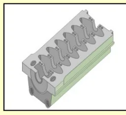
The cylinder liner is a cylindrical sleeve mounted in the openings of the frame. It forms the bore the piston runs in, and it is also the surface the cooling water acts on.
How it is held:
- The top flange of the liner is pressed against the top of the frame by the cylinder cover. The cover is what clamps the liner down.
- The bottom portion of the liner is free to expand, which accommodates thermal expansion. This freedom is essential: the liner runs hot and grows, and if both ends were clamped it would distort.
How it is sealed:
- There is direct contact between the cooling water and the outer surface of the liner, which is why this construction is called a well liner.
- Two sealing rings seal the water chamber from the crankcase. They are fitted in grooves in the guide surface of the cylinder liner.
- The sealing rings — usually called O rings — prevent water leaking into the crankcase and also prevent oil from the crankcase entering the water jackets. They have to work in both directions.
- A tell-tale leak-off hole is provided between the upper and lower rings to indicate leaks due to damaged or worn-out O rings. This is a diagnostic feature, and a tell-tale that starts weeping is telling you a ring has failed — water or oil is getting past the first seal and the second is holding it, for now.
The liner wears
The cylinder liner is designed to withstand gas pressure and the side thrust of the piston, and it is subject to continuous abrasive and corrosive attack. It therefore wears, and it wears neither evenly nor circularly. The liner is gauged at regular intervals as specified in the maintenance manual, and the records kept, because it is the rate of wear that matters as much as the absolute figure.
The gauging procedure, the wear rates to expect, the causes of wear, the pattern that points to the cause, and the limits at which a liner is condemned are in Chapter 12, which owns the measurement.
2. The piston
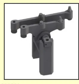
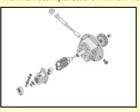
The piston transmits the gas force to the crankshaft through the connecting rod. It also has to contain the combustion pressure, transfer heat to the cooling oil, and guide itself on the liner.
How it is built:
- The piston is attached to the small end of the connecting rod by a gudgeon pin.
- On an auxiliary engine the piston is usually a monobloc construction, made of aluminium alloy for a medium-speed engine, and it is oil cooled.
- Close to the piston crown and the piston ring zone, the piston has a cooling oil space. This is where the heat has to be removed, because the crown takes the flame and the ring belt takes the friction.
- Cooling oil is used oil from the engine's lubricating oil system. It is supplied to the cooling oil space through a channel from an oil groove in the piston pin bosses. A duct situated diametrically opposite the inlet channel drains the oil out again, so that the oil is forced to traverse the hot zone rather than short-circuiting through it.
- The piston is equipped with three compression rings and one oil scraper ring.
The piston in a four-stroke engine
The four-stroke trunk piston has a different job from a two-stroke piston, and it looks different.
- The crown forms the combustion chamber roof, so it must tolerate the flame. The shape of the crown is set by the combustion chamber design and by the injector's spray pattern.
- The top land — the strip of piston between the top of the top ring and the crown — is the hottest part and the part most prone to carbon build-up.
- The ring belt carries the compression rings and the oil scraper ring.
- The skirt transmits the side thrust, caused by the varying angularity of the connecting rod as it swings. This is a duty a two-stroke crosshead piston does not have, because the crosshead and its guides take the side thrust instead. The skirt is therefore a load-bearing and wearing surface, and it is the reason a trunk piston is longer and heavier than a crosshead piston of the same bore.
Because the skirt takes side thrust, the piston also has to be lubricated and cooled at the skirt, and the liner has to resist the resulting wear. This is the fundamental difference between the auxiliary engine and the main engine, and it is why the two have different lubricating arrangements.
Piston rings
Piston rings are designed for maximum sealing effect and minimum wear rate. On a medium-speed auxiliary engine the set is normally:
- Three compression rings — the gas seal. The upper rings run hottest and wear fastest; the top ring may sit in a hardened carrier or a ring groove insert, because an aluminium alloy groove cannot take the load on its own.
- One oil scraper ring — the oil control ring. Its job is to scrape surplus oil off the liner and return it to the crankcase, and its condition decides how much oil the engine consumes.
A ring's performance depends on:
- Its fit in the groove — too much side clearance and the ring pumps oil; too little and it seizes when hot.
- Its end gap — set so that the ring can expand with temperature without butting.
- Its radial pressure against the liner — decided by its own elasticity and by the gas pressure behind it, which forces it out against the bore.
- The liner's surface — a worn or glazed liner will not let the rings bed in.
- Heat deformation — a distorted piston or a distorted liner will not let the rings seal all the way round.
3. The gudgeon pin
The gudgeon pin joins the piston to the connecting rod. It rests in two bored holes in the piston and passes through the eye of the connecting rod, joining the two together.
On a medium-speed auxiliary engine the pin is normally fully floating, which means it can turn freely in the pin bosses of the piston as well as in the connecting rod bush. A fully floating pin wears evenly all round instead of wearing flats, and lasts much longer.
The pin is kept in place in the axial direction by two circlips, one at each end. The circlips are the only thing preventing the pin from moving sideways and scoring the liner, so their condition at every overhaul matters more than their size suggests.
The pin is equipped with channels and holes for two purposes:
- Lubrication of the pin bosses — the surfaces the pin turns in.
- Supply of cooling oil to the piston — the pin is the route by which oil reaches the piston's cooling space.
That second function is the reason the gudgeon pin is more than a bearing pin on a modern trunk piston engine. If a pin's oil passage blocks, the piston loses its cooling, and the failure that follows is severe.
4. The connecting rod
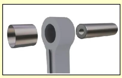
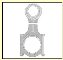
The connecting rod connects the piston to the crankshaft. It is drop forged, and it has two ends:
- The small end is connected to the piston, through the gudgeon pin and its bush.
- The big end is connected to the crankshaft, around the crank pin.
At the big end, the joint faces on the connecting rod and the bearing cap are serrated. This is done to ensure precise location and to prevent relative movement of the parts. A serrated joint cannot creep sideways the way a plain faced one can, and the serrations also carry some of the shear load rather than leaving it all to the bolts.
Oil supply:
- The connecting rod has a bored channel to supply oil from the big end to the small end eye. This is how the gudgeon pin bush and, through it, the piston cooling space, get their oil.
- Lubricating oil for the connecting rod bearing and the piston is supplied from the adjacent main bearing through bores in the crankshaft. So the oil path is: main gallery, main bearing, crankshaft drilling, big end bearing, connecting rod drilling, small end bush, piston cooling space, and out again by the drain duct.
- The big end bearing is of trimetal type — steel shells lined with lead bronze and coated with a thin running-in and protection layer. The coating is there to let the bearing bed itself in during the first hours of running, and to protect the journal if the oil film is momentarily lost.
What goes wrong at the connecting rod
Two failures account for most connecting rod trouble.
Bottom end bearing failure is usually a lubrication failure — loss of oil pressure, contaminated oil, a blocked oil passage, or a bearing fitted with the wrong clearance. The bearing wipes, the clearance opens up, and the knocking that follows is the warning. If it is not acted on, the crank pin is damaged and the crankshaft has to come out.
Bottom end bolt failure is more dangerous, because it is sudden. The bolts are subject to repeated stress and fluctuating stress every revolution, and they are tightened to a specified stretch, not a torque. Bolts that are re-used beyond their life, or tightened by feel, can fail and let the rod go through the crankcase. This is one of the classic causes of a crankcase explosion.
Top end bearings
Top end bearings — the bushes in the small end — and the gudgeon pin are checked for clearance and for surface condition at overhaul. A worn top end bush shows up as a knock and as a change in the piston's position, and it allows the piston to tilt in the bore, which shows up as abnormal liner wear.
5. How the wear parts fit together
It is worth seeing the piston, rings, liner and rod as one system rather than four separate parts, because that is how they behave.
- The rings seal against the liner. If the liner is worn or oval, no ring will seal it.
- The piston skirt bears on the liner. If the skirt is worn or the liner is distorted, the piston tilts, and the rings stop sealing on the part of the bore the tilt exposes.
- The gudgeon pin locates the piston on the rod. If the top end bush is worn, the piston tilts.
- The rod's oil passages feed the pin and the piston crown. If they are blocked, the pin and the crown overheat.
- The liner's O rings keep the water out of the crankcase. If they leak, the lubricating oil is contaminated, and every one of the parts above wears faster.
That is why liner gauging records, ring gap records and bearing clearance records are kept together, and why a single reading out of trend is followed up rather than filed.