
Maintenance and Troubleshooting — Overhauls, Tappet Clearance and Reading a Fault
The work that keeps an auxiliary engine reliable, and the reasoning that turns a symptom into a diagnosis.
Key Principles at a Glance 5 points
- The point of maintenance is not to follow a schedule but to make the engine's condition known.
- An engine whose liner has been gauged, whose exhaust temperatures are compared, whose oil is analysed and whose valves are measured is an engine whose faults are found while they are still cheap.
- An engine that is only repaired when it stops is an engine that will stop at the least convenient moment.
- The overhaul covers the cylinder head and valves, tappet clearance, valve timing, the fuel injection equipment, the cylinder liner and the air start valve.
- The measurements are the maintenance, and the repairs are what the measurements tell you to do.
1. The pattern of maintenance
The maker's intervals, clearances, torques and fits govern, and the maker's special tools are used. A component is not returned to service until the measurement that proves it is fit has been taken and recorded.
An auxiliary engine accumulates far fewer running hours than a propulsion engine, and its maintenance is therefore driven as much by time as by hours run. This has a consequence that catches people out: an engine that has run for a few hundred hours in a year still needs its oil changed, its batteries checked and its cooling water tested, because those items age whether or not the engine runs.
The work divides into four kinds:
- Running checks — the readings taken every watch, covered in the operating chapter. They are the early-warning system.
- Routine servicing — filters, oil, cooling water treatment, battery, at fixed intervals.
- Planned overhaul — cylinder heads, valves, fuel injectors, fuel pumps, bearings, at fixed intervals or hours.
- Condition-based work — jobs done because a measurement says so: liner gauging, oil analysis, vibration, exhaust temperature comparison.
The four feed each other. A running check shows a rising exhaust temperature; the planned overhaul finds the cause; the measurement taken during the overhaul confirms the fix. Maintenance is a loop, not a list.
2. Overhauling the cylinder head and valves
The cylinder head and its valves take the most punishment of any part of a four-stroke engine, and they are the parts most often overhauled.
Removing and stripping
The head is removed with the engine cold, the fuel and starting air connections broken and blanked, and the cooling water drained. The valves are then stripped from the head. What is looked for at this point is the condition of everything the valve touches:
- The valve face and the seat. A valve that has been burning shows a blackened, pitted or eroded face, and the seat underneath shows the matching damage. The two are examined together, because the valve cannot seat properly on a damaged seat no matter how well it is ground.
- The valve stem and guide. Wear in the guide lets the valve rock, which stops it seating squarely and leads to burning. The stem is measured and the guide is measured, and the clearance between them is compared with the maker's limit.
- The springs. Free length and squareness are checked. A spring that has sagged or cracked will not hold the valve closed at the right pressure, and a broken spring can drop a valve into the cylinder.
- The rotator or roto cap, where fitted. It turns the valve a little at each lift so that the valve and seat wear evenly. A seized rotator is a fault in itself and causes uneven wear.
- The seat insert, where the seat is a separate insert rather than cut into the head. The insert is replaced when it can no longer be restored by grinding.
Lapping and grinding
There are two distinct operations, and confusing them causes damage.
Lapping is the finishing operation. The valve face and the seat are worked together with a fine abrasive paste until a continuous, unbroken, matt-grey band of contact is produced around the full circumference of both. The band is the proof that the two surfaces match. Lapping is done by hand or with a slow mechanical lapper, with the valve lifted and turned a fraction at each stroke so that the abrasive cuts evenly.
Grinding is the cutting operation, done with a valve refacing machine or a seat grinding stone, and it removes metal to restore the angle. It is a machining operation with a definite limit.
The contact band is the measure of the job:
- The band must be continuous and unbroken, going right round the seat. A band that fades out at one point means the valve is not seating there, and the gap will burn through.
- The band must be not less than about 1.5 mm wide. A narrower band cannot carry the heat away from the valve face, and it will overheat and burn. A wider band looks better but seats less sharply and is more prone to collecting carbon that holds the valve open.
- The band must be in the correct position on the seat, matching the maker's drawing. A band at the wrong place means the valve has been refaced too many times, or the seat has been cut too deep.
Why repeated grinding is wrong
It is tempting to think that a valve which is not sealing should simply be ground again. It should not, and the reasons are mechanical:
- Every grinding removes metal from the valve head and lowers it into the head. As the valve sinks, the valve stem protrudes further, which changes the geometry of the rocker arm and the tappet clearance.
- Every grinding removes metal from the seat and sinks the seat into the head. Taken far enough, the seat can no longer be restored and the whole head has to be replaced — an expensive outcome caused by a series of cheap repairs.
- The valve head gets thinner as it is ground, until it can no longer dissipate the heat of combustion and it warps or cracks.
- Grinding hides the cause. If a valve is burning repeatedly, the fault is usually not the valve: it is the injector spraying badly, the cooling at that seat, the tappet clearance set wrong, or the valve rotator seized. Grinding the valve and returning it to service without finding the cause guarantees the same failure again.
The correct rule is that a valve is ground only when the measurement says it needs it, and only as far as the maker's limits allow. Beyond that limit the valve is replaced.
Reassembling
On reassembly, everything is scrupulously clean before it goes together. Grit or carbon left on a seating face will hold the joint open. The valve stem is lubricated sparingly, the springs are fitted the right way up, and the valve is checked for free movement in its guide. The head is then fitted with a new gasket, and the nuts or bolts are tightened in the maker's sequence and to the maker's torque — a sequence that exists because an unevenly tightened head distorts and leaks.
Caged exhaust valves
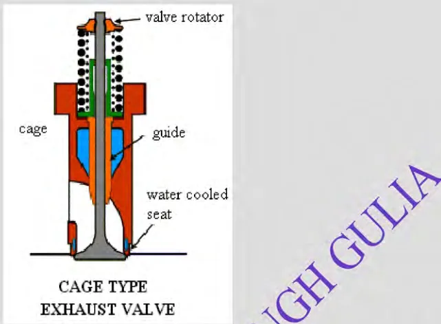
Some engines use a caged exhaust valve, in which the valve and its seat are contained in a cage that is a separate assembly from the head. The advantage is that the whole valve assembly can be withdrawn, serviced and replaced without removing the cylinder head. On an engine where the exhaust valves are the most frequent maintenance item, this saves a great deal of work and a great deal of disturbance to the head joint.
3. Tappet clearance
The tappet clearance is the small gap left in the valve train when the valve is closed, and it exists because the parts expand as the engine warms. It is one of the most important settings on the engine and one of the easiest to get wrong.
What the clearance does
- Too small a clearance means that as the engine warms and the parts expand, the valve is held slightly off its seat. It never seats properly, so it overheats and burns, compression is lost and the valve may be struck by the piston.
- Too large a clearance means the valve opens late and closes early, so the engine breathes badly, loses power and runs hot. It also hammers the valve train, because the gap is taken up by an impact rather than a smooth lift.
Setting it
The clearance is set with the engine cold, on the base of the maker's cold clearance figure, using a feeler gauge of the correct thickness. The procedure:
- Turn the engine so that the valve to be set is fully closed and the cam follower is on the base circle of the cam — the position in which there is no lift at all.
- Check the firing order so that the correct cylinder and valve are being set, and set the valves in the maker's sequence rather than in numerical order.
- Slacken the locknut and adjust the tappet screw until the feeler gauge of the correct thickness will just pass with a slight drag.
- Hold the screw and tighten the locknut, then re-check the clearance, because tightening the locknut can move the screw.
- Record the clearance and the cylinder it belongs to.
The rocking method
A reliable way to find the correct position for setting a valve is the rocking method: turn the engine until the valve on the opposite end of the same cylinder — or the corresponding valve in the cylinder at the other end of the firing order — is just rocking, that is, just beginning to open as the other is closing. In that position the valve being set is guaranteed to be on the base circle. This avoids relying on timing marks that may be hard to read and gives the same answer every time.
The clearances are set cold and checked hot. A clearance that is correct cold but wrong hot points to a valve train problem rather than a setting problem.
4. Valve timing
Valve timing is the relationship between the position of the crankshaft and the moment the valves open and close. It is set by the camshaft and the camshaft drive, and it is verified rather than adjusted in normal service.
The timing is checked by turning the engine to a known crankshaft position and measuring the valve lift, or by using the timing marks on the camshaft drive. The marks are there for this purpose and they are used whenever the camshaft drive has been disturbed — after a gear train overhaul, for example.
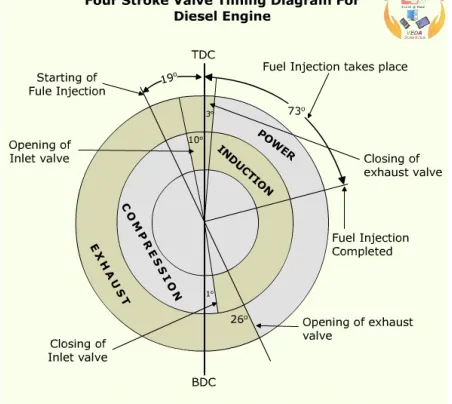
The reason timing matters so much is that a four-stroke engine has only one exhaust stroke in four, and the valve events are arranged around it deliberately. The exhaust valve opens before bottom dead centre to give the burnt gas a start on its way out, and the inlet valve opens before top dead centre so that the incoming air is already moving when the piston starts down. Get the timing wrong and the engine will still run, but badly — down on power, hot and smoky — and no amount of fuel adjustment will fix it.
The camshaft drive
The camshaft itself, its drive, the half-speed gear ratio and the shrunk-on cams that can be adjusted hydraulically are described in Chapter 5, which owns the camshaft. What matters here is the consequence for maintenance: whenever the gear train has been disturbed, the timing must be re-verified, and where the cams are of the hydraulic-adjustment type the adjustment is made by the maker's procedure and the timing re-checked before the engine returns to service. A camshaft drive that is a tooth out is not a subtle fault — a small timing error causes loss of power and overheating, and a large one stops the engine firing at all.
5. Fuel injection equipment
The fuel injection pump
The injection pump is a precision component, and it is treated as one. The pump plunger and its guide or barrel are matched to each other and are not interchangeable — a plunger from one pump will not necessarily fit the barrel of another, even of the same type, because the clearance between them is of the order of a micron and each pair is lapped together. Mixing them destroys the pump.
Overhaul consists of stripping the pump, cleaning all parts, inspecting the plunger and barrel for scoring and wear, checking the delivery valve and its spring, and reassembling with new seals. The plunger is measured for wear, and the barrel for the same; a pair that no longer holds pressure is replaced as a set.
On reassembly the pump is fitted and the timing re-set — the moment of injection is determined by the pump's position on its camshaft, and it must match the engine's requirement. The pump is then calibrated so that each cylinder receives the same quantity of fuel, which is what makes the exhaust temperatures match.
The fuel injector
The injector is removed, stripped and cleaned, and the nozzle is examined. The checks are:
- The nozzle spray pattern, tested on a nozzle tester. A nozzle that dribbles, that produces an uneven spray or that has a poor pattern is replaced.
- The opening pressure, set with shims or by adjusting the spring to the maker's figure, and checked on the tester.
- The needle and seat, examined for wear and for the erosion that hot combustion gases cause.
- The carbon on the nozzle tip, removed without damaging the seat.
The injector is then refitted with a new copper or steel sealing washer, which is what seals the compression and keeps the nozzle at the right depth in the head. A re-used washer that has hardened will leak compression past the injector, and the result is a noisy, hot-running cylinder.
6. The cylinder liner
The cylinder liner is the one component whose wear is measured as a matter of routine, because the measurement predicts the rest of the engine's life.
Gauging
The liner is gauged at regular intervals using an internal micrometer or a dial gauge on a setting jig. The measurement is taken at several heights up and down the liner and in two directions — in line with the crankshaft and across it — because the liner does not wear evenly. The greatest wear is normally at the top of the ring travel, where the rings press hardest and the combustion pressures are highest, and the wear is greater across the crankshaft axis than along it.
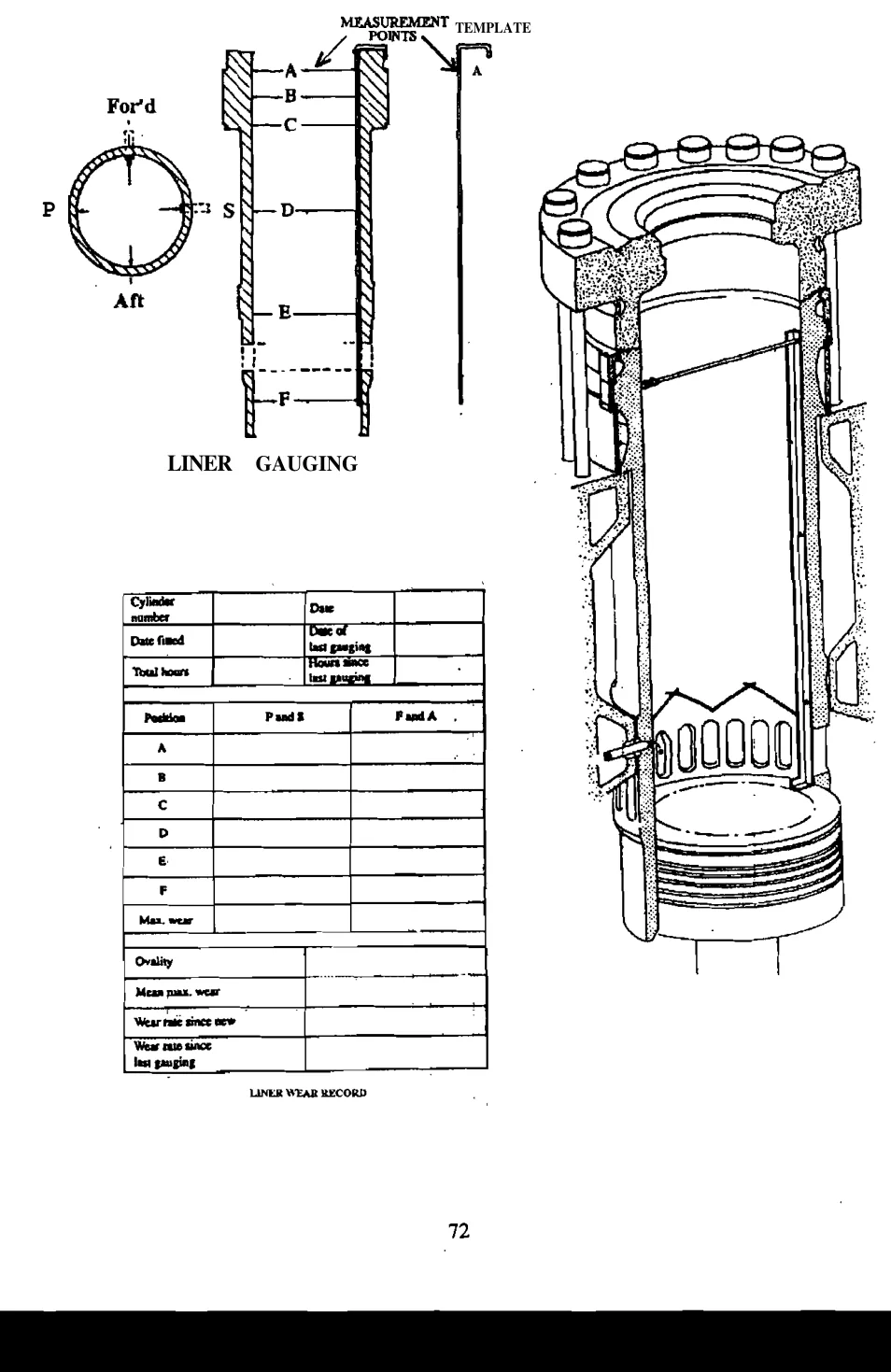
The results are recorded and plotted against running hours, which gives the wear rate. The wear rate is what matters: a single measurement tells you the size, but a series of measurements tells you how fast it is going and when the liner will reach its limit.
A wear rate of the order of 0.1 mm per 1,000 running hours is the sort of figure used as a reference. A liner wearing much faster than that is telling you something — abrasive material in the air or the fuel, the wrong lubricating oil, a badly running injector washing the oil off the walls, or a cooling problem distorting the liner.
What causes liner wear
- Abrasive material — dust drawn in with the combustion air, or catalytic fines in the fuel that have got through the treatment. Both grind the liner and the rings.
- Corrosion — acid products of combustion condensing on a cold liner, where the liner surface is below the dew point of the acid, or where the lubricating oil's alkalinity has been exhausted before the oil has spread across the surface. This is why running the engine at the right temperature matters so much.
- Poor lubrication — oil that is too thin, contaminated, or of the wrong alkalinity, or oil washed off the wall by an injector that is over-fuelling or spraying badly.
- Fuel impingement — fuel sprayed onto the liner wall rather than into the air, which washes the oil film off and burns in the wrong place.
- Distortion — uneven cooling, a badly fitted liner, a distorted cylinder cover or an unevenly tightened head distorts the liner, so the rings no longer follow it evenly.
- Overload — running the engine above its rating increases the pressure of the rings on the liner and the temperature of both.
The pattern of the wear points to the cause. Whether the liner is worn evenly, or oval, or tapered, or worn in a "clover leaf" distinguishes a general abrasive or corrosive condition from a localised distortion or a single badly spraying injector. The measuring points are set by a template so that the readings are comparable from one gauging to the next.
When the liner is condemned
A liner is replaced when the wear, ovality or taper exceeds the maker's limit, when the wear rate suggests it will exceed the limit before the next opportunity, or when it is scored, cracked or corroded. The rings are replaced whenever the liner is replaced, and the piston is examined at the same time.
7. The air start valve
The air start valve on an auxiliary engine is a small but critical component, and its maintenance has its own requirements because it handles high-pressure air and hot combustion gas from opposite ends.
- The piston rings must be free in their grooves. A ring stuck in its groove will not seal, and the valve will leak starting air into the cylinder continuously — which means the engine may not start, or may fire at the wrong time.
- The butt clearances of the rings are checked, especially where the rings are brass. Too little clearance and the ring seizes as it warms; too much and it does not seal.
- The valve and its seat are ground and lapped to a good contact, in the same way as a cylinder valve, and the same band requirement applies.
- All parts are scrupulously clean before reassembly. The clearances in this valve are small, and a particle left inside will hold it open.
- The sliding surfaces are lubricated sparingly with a suitable grease — a molybdenum disulphide grease is the usual choice — because a valve that is dry will stick, and a valve that is over-lubricated will collect dirt.
A leaking air start valve is a common cause of a hard-to-diagnose fault: the engine may fail to start, or may knock or fire unevenly, and the cause is found only when the valve is removed and examined.
8. Reading a fault
Most auxiliary engine faults announce themselves in the instruments before they become mechanical. The useful discipline is to read the measurements in the order that narrows the field fastest.
| Symptom | The first things to check | What it usually turns out to be |
|---|---|---|
| One cylinder's exhaust temperature high | The injector for that cylinder | Over-fuelling injector, or a nozzle that is dribbling |
| One cylinder's exhaust temperature low | The injector and the compression | A blocked or worn injector, a leaking valve, or a broken ring |
| All exhaust temperatures high | The load and the charge air pressure | Engine overloaded, or fouled turbocharger, or a dirty charge air cooler |
| Lubricating oil pressure falling | The oil level and the oil temperature | Diluted or degraded oil, a worn pump, or a bearing opening up |
| Lubricating oil pressure low when hot only | The oil grade and the cooler | Wrong viscosity oil, or oil that has broken down |
| Cooling water temperature rising | The sea water valve and the cooler | Fouled cooler, failed pump, or a closed valve |
| Sump level rising | Whether it is fuel or water | A leaking injector sleeve, a cracked liner, or a fuel leak |
| Engine will not start on air | The starting air pressure and the air start valve | Low air pressure, a stuck air start valve, or a faulty distributor |
| Engine starts but will not fire | The fuel supply and the rack | Air in the fuel system, a closed valve, or the rack not moving |
| Engine hunts | The governor and its drive | Governor fault, worn linkage, or a governor that is due for overhaul |
| Engine runs on after the fuel is cut | The rack and the governor linkage | Rack sticking, or the governor not returning to the no-fuel position |
| Rising vibration | The mounting, the coupling and the alignment | Worn resilient mounts, loose holding-down bolts, or a coupling fault |
The pattern in the table is that the cheap and quick checks come first, and that most faults are found in the fuel, the oil or the cooling rather than in the mechanical parts. A fault that survives those checks is a mechanical fault, and it is found by measurement, not by guesswork.
9. What maintenance is really for
The point of all of this is not to follow a schedule. It is to make the engine's condition known. An engine whose liner has been gauged, whose exhaust temperatures are compared, whose oil is analysed and whose valves are measured is an engine whose faults are found while they are still cheap. An engine that is only repaired when it stops is an engine that will stop at the least convenient moment.
That is the whole of it: the measurements are the maintenance, and the repairs are what the measurements tell you to do.