
Starting the Engine — Air Start Valve, Distributor and the Four Interlocks
How a stopped auxiliary engine is turned over and brought to firing speed, and what has to be true before the air is admitted.
Key Principles at a Glance 7 points
- Starting looks simple and is not: before admitting the air, the control system must make sure the turning gear is not engaged and that the air will start the engine in the correct and desired direction.
- Then it must admit fuel when the engine reaches firing speed and cut off the starting air — those four requirements are the interlocks, and each one exists because of an accident.
- An engine started with the turning gear in mesh wrecks the gear and anything in its path, so on many engines this is mechanically interlocked as well as electrically.
- A starting air system that admits air to the wrong cylinders or at the wrong time turns the engine backwards, which can damage the pumps and the valve gear.
- Fuel admitted before the engine is turning fast enough to fire collects in the cylinders and washes the oil off the liners, and air left admitted after firing holds the start valves open and fights the governor.
- The indicator cocks matter in both directions: open they show whether water, oil or fuel has collected in a cylinder, and closed they let the engine fire — starting with liquid in a cylinder and the cocks shut is a hydraulic lock, and a bent connecting rod is the usual result.
- Prelubrication is a system function, not merely a procedural step: it fills the galleries, the bearings and the piston cooling spaces with oil and confirms by oil pressure that the system is sound.
1. Why the engine is started on air
The engine maker's starting sequence and the ship's interlocks govern. The turning gear must be disengaged and locked out, and clearance obtained, before any attempt to start.
A diesel engine cannot start itself. There is no ignition system — the fuel ignites because the air in the cylinder is hot enough after compression. So the engine must first be turned over at speed sufficient to compress the air to ignition temperature, and only then can fuel be admitted.
Marine diesel engines are normally started with compressed air. The air is admitted at a pressure of about 15 to 30 bar. On a medium-speed auxiliary engine the starting air pressure is typically 25 to 30 bar.
The air does the work directly. It is admitted into the cylinder above the piston while the piston is just past top dead centre on what would be the power stroke, and it pushes the piston down, turning the crankshaft. Each cylinder in turn gets its charge of air in the right order, and the engine accelerates. When the required speed is achieved, the fuel is admitted and firing takes place.
2. The air start valve
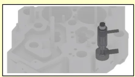
The air start valve — also called the starting valve — is fitted on the cylinder head, which encompasses the combustion chamber. It is mounted on the head by an integral flange in the holder and two studs with distance pieces and nuts — the same mounting as the fuel injector.
It operates pneumatically, moving down a spring-loaded valve and allowing the high-pressure air to enter the combustion chamber. Its whole job is to open and close the passage of high-pressure air into the combustion chamber, and it must do so reliably, at speed, thousands of times, and then seal perfectly when the engine is firing.
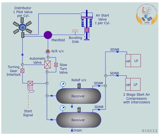
The air distributor delivers high-pressure air to the air start valve through a high-pressure pipe. So there are two pressures involved: the starting air which actually turns the engine, and a control or pilot air signal which tells the valve when to open.
How the valve is kept shut when it should be
The design problem is this: the valve has 30 bar of starting air sitting on top of it all the time, and a cylinder full of hot gas underneath it for most of the cycle. It must not open when the engine is firing.
There are two solutions in common use.
The pneumatically balanced valve — as used on MAN B&W engines:
- Main starting air at about 30 bar enters the chamber above the valve through circumferential ports in the valve body.
- The air pressure will not open the valve, because a spring is holding it shut, and because the area of the balance piston is the same as that of the valve lid, so the valve is pneumatically balanced. The pressure pushes equally on both the top of the valve lid and the underside of the balance piston, and the two cancel.
- To open the valve, air at 30 bar from the air start distributor enters the top of the valve body and acts on a piston. That force overcomes the spring, and the valve opens.
- When the air signal from the distributor is vented, the spring closes the valve.
- When the start sequence is finished, the main air start pressure is vented through holes in the main start air manifold, so the valve is not left sitting under pressure.
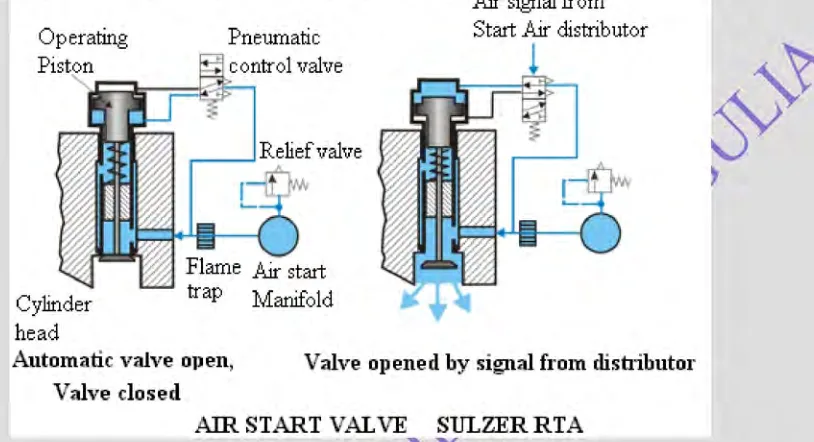
The stepped piston valve — as used on Sulzer engines:
- The Sulzer air start valve uses air on both sides of the operating piston to maintain positive closing. The piston is stepped.
- The reason for this is so that the starting air valve will not open when the gas pressure in the cylinder is higher than the starting air pressure — that is, when the cylinder is firing. The larger area on the closing side means the cylinder gas has to overcome more than the starting air can supply.
- Once the valve starts to open, the opening is accelerated when the larger diameter piston has the opening air acting on it.
- The stepped piston also damps the closing, because air gets trapped in the annular space formed when the smaller diameter piston enters the upper part of the cylinder. A valve that slammed shut would hammer its seat.
- The air to operate the valve comes from the main air start supply. The distributor pilot air operates the pneumatic changeover valve.
Materials. The body of the valve may be of mild steel, the spindle of high tensile or stainless steel, and the valve and seat may have their contact faces stellited or hardened.
Flame traps and bursting caps
Flame traps or bursting caps are fitted at each air start valve. They are there for the case where the valve leaks and cylinder gas at firing pressure gets back into the starting air line. A flame trap stops a flame front travelling down the pipe; a bursting cap is a non-reclosing disc that ruptures to release the pressure.
Neither is a complete answer. Protection of the bursting-cap type failed to prevent a serious explosion with the loss of seven lives in one recorded case. The real protection is keeping the valves in good order and keeping oil out of the starting air system.
The air start valve as a brake
The starting air valve has a second use. If the engine is required to reverse while there is still way on the ship, the engine is being driven by the propeller, and it may be a while before it comes to a halt. To speed up the process, starting air is admitted while the engine is still running ahead, although the start air distributor will have been retimed to give astern. The air acts as a brake, slowing the engine until it can be started in the reverse direction. This is why the valve and the distributor must be able to operate at speed and against pressure.
3. The air start distributor
The starting air distributor normally consists of a series of pilot valves, one for each cylinder, arranged radially around a cam.
- It is timed to the engine and driven from the camshaft.
- The distributor opens the main air start valves in the correct sequence.
- The air start valve is located in the cylinder head. When it is opened by the air signal from the distributor, compressed air at about 30 bar flows into the cylinder, forcing the piston down.
Because the distributor is driven from the camshaft, the timing of the air admission is locked to the crankshaft position — the engine cannot have air admitted to the wrong cylinder at the wrong time unless the distributor has been assembled or timed wrongly.
The distributor is also where the direction of starting is decided on a reversible engine. Re-timing the distributor reverses the sequence, which is how the air brake function above is achieved.
4. Where the starting air comes from
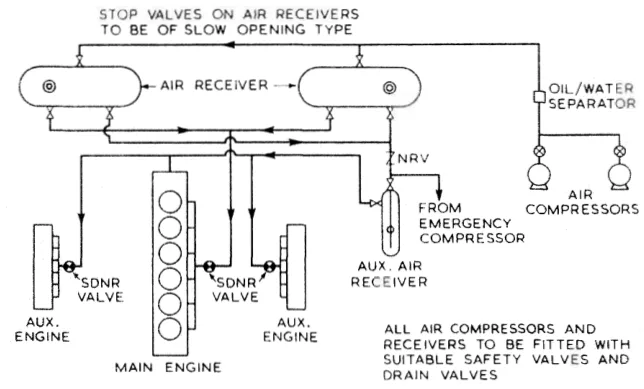
Starting air for auxiliary engines may be taken directly from the main engine air start receivers, or from a small auxiliary receiver which can be kept at full pressure.
The second arrangement is the more common on a ship that must be able to start a generator without running the main engine. The auxiliary receiver is kept pressed up at all times, and the standby set can therefore be started from cold without help.
The low-pressure control air system — the air used for instrumentation and remote control, at a much lower pressure than the starting air — is supplied ideally from a low-pressure, oil-free compressor. The supply may be obtained from the main air start reservoirs through reducing valves or pressure regulators, driers, oil traps and filters.
Why the air must be clean and dry
Two things in the starting air system cause trouble, and both are controllable.
Oil. Lubrication of the air start system components must be limited, as excess lubrication could cause the air start valves to be stuck by grease which has become hardened by the heat, and oil could accumulate in the pipes. A stuck air start valve that will not close is a direct route to an air start line explosion — hot cylinder gas blows back down the line into a pipe full of oil mist. This is one of the three classic engine room explosions, alongside the crankcase explosion and the scavenge fire.
Water. The draining of compressor coolers and air receivers is important, and the drains on air start systems are also checked. Water carried over from the compressor collects in the receiver and in the low points of the pipework; it causes corrosion from the inside and it can slug through into a cylinder.
Compressors
The starting air is made by multi-stage compressors, and the reason is worth knowing. A single stage compressor used to provide air at the high pressures required for diesel engine starting would generate compression temperatures of a level similar to those in a diesel. Such heat would be sufficient to ignite vaporised oil in the same way as in a compression-ignition engine. The heat would also be wasteful of energy.
So the compression is split into stages with intercooling between them. The intercooler brings the air temperature down and its density up, which reduces the work of the next stage; and it is the intercooler drains that must be kept clear.
5. Starting a small set on a battery
Not every auxiliary engine starts on air. A small set may be started by an electric motor drawing its power from a battery, normally charged through a transformer/rectifier. This is the usual arrangement for an emergency generator, where the whole point is that the set must start with no other power available — and it makes the starting battery a piece of safety equipment in its own right, kept charged and tested.
The starting arrangements of the emergency set, the checks that keep its battery fit, and the other requirements placed on it are covered in Chapter 10.
6. The interlocks and the starting system
Starting looks simple and is not. Before admitting the air, the control system must make sure that the turning gear is not engaged, and must make sure the starting air will start the engine in the correct and desired direction. Then it must admit fuel when the engine reaches firing speed, and cut off the starting air.
Those four requirements are the interlocks, and each one exists because of an accident:
- Turning gear not engaged. An engine started with the turning gear in mesh wrecks the gear and anything in its path. On many engines this is mechanically interlocked as well as electrically, so that it cannot be defeated by a control fault; on all of them it is a rule.
- Correct direction. A starting air system that admits air to the wrong cylinders, or at the wrong time, turns the engine backwards, which can damage the pumps and the valve gear. The direction is set by the distributor and the camshaft drive, and it is verified after any work on either.
- Fuel admitted at firing speed. Fuel admitted before the engine is turning fast enough to fire collects in the cylinders and washes the oil off the liners; fuel admitted too late and the engine does not catch. The governor and its load limit setting control this.
- Starting air cut off. Air left admitted after firing holds the start valves open and keeps the engine on air, which fights the governor and can let the engine run on starting air alone.
Two further points belong to the starting system rather than to the sequence.
The indicator cocks matter in both directions. Open, they let you see whether anything — water, oil or fuel — has collected in a cylinder, and they let the engine be turned over without compression. Closed, they let the engine fire. Starting an engine with liquid in a cylinder and the cocks shut is a hydraulic lock, and a bent connecting rod is the usual result.
Prelubrication is a system function, not merely a procedural step. The pre-lubricating oil pump fills the oil galleries, the bearings and the piston cooling spaces with oil before any load comes on them, and confirms by oil pressure that the system is sound. On an automatically controlled set that has been kept warm, the pre-starting preparation is simply lubricating oil priming.
The procedure as it is actually carried out on board — the checks, their order, the pressures, the governor setting and the running-up — is in Chapter 11, which owns the operating routine.