
Compressor Pistons, Piston Rings and Rider Rings
The rings seal and the rider rings carry, so confuse the two and you will keep replacing the wrong part.
Key Principles at a Glance 7 points
- Piston rings seal gas and rider rings carry the piston's weight off the cylinder bore, so the two do different jobs and wear for different reasons.
- Ring butt clearance and side clearance are set by the manufacturer and change with temperature and wear, so they are measured and recorded rather than estimated.
- In a non-lubricated cylinder the rider rings are the bearing surface, which is why rider-band wear is the life-limiting measurement on those machines.
- Blow-by past worn rings reduces capacity, raises discharge temperature and contaminates the crankcase, so ring wear appears first as a performance loss.
- Repeated rider-band wear is a geometry problem of bore distortion, rod misalignment or excessive clearance, and not a ring-material problem.
- Lubricated and non-lubricated cylinders need different ring materials, different running-in and different inspection intervals.
- Piston and cylinder clearances must be checked with the piston at both dead centres, because the critical measurement is usually the smallest one.
Learning objectives
By the end of this chapter you should be able to:
- explain how the piston, piston rings, rider rings, and cylinder bore work together;
- distinguish sealing rings from rider or guide rings;
- compare lubricated and non-lubricated piston arrangements;
- identify common piston materials and construction forms;
- explain the importance of piston-to-cylinder and piston-end clearances;
- recognise ring wear, ring breakage, scuffing, and rider-band failure;
- connect piston condition with capacity, temperature, oil carryover, and power; and
- prepare an inspection and replacement checklist for piston assemblies.
1. The piston assembly in the compressor
The piston assembly forms the moving boundary of the compression space. It must transmit gas pressure to the piston rod, seal the cylinder bore, tolerate temperature and pressure cycling, and remain accurately aligned while moving at high speed.
A typical piston assembly contains:
- piston body or carrier;
- piston-rod attachment;
- piston rings;
- rider or guide rings where fitted;
- ring grooves and lands;
- end faces;
- counterbore or hub;
- retaining nut, studs, or bolts; and
- locking devices.
The cylinder, piston, rings, rod, packing, and crosshead form one functional system. A ring failure may be caused by a dirty inlet, poor lubrication, incorrect clearance, rod misalignment, excessive temperature, or cylinder damage rather than by the ring material alone.
2. Piston functions
The piston must:
- transmit the gas force to the piston rod;
- maintain a controlled radial relationship with the cylinder;
- provide grooves or carriers for sealing and rider rings;
- resist pressure and inertia loading;
- tolerate thermal expansion;
- limit gas leakage between cylinder ends; and
- avoid contact with the cylinder wall or head.
In a single-acting cylinder, compression occurs on one side of the piston. In a double-acting cylinder, both ends compress gas, so the piston has a pressure face at each end and the rod passes through packing at one side.
The piston is not intended to seal by metal-to-metal contact with the cylinder. Sealing is provided by piston rings, while the piston body is supported by the bore geometry and, in many designs, rider rings.
3. Piston construction
3.1 One-piece pistons
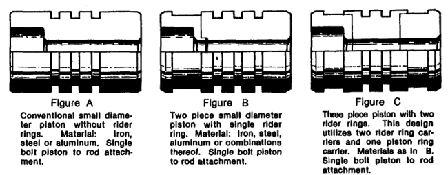
Small pistons may be made as a single iron, steel, or aluminium component. The piston ring grooves are machined directly into the body. This arrangement is simple and economical, but material choice must provide adequate strength and groove wear resistance.
3.2 Two-piece pistons
Larger pistons may be split into two pieces for easier hollow casting and weight control. Aluminium may be selected when reduced reciprocating mass is important. Cast iron or steel may be selected where strength, wear resistance, or ring-groove durability dominates.
3.3 Three-piece pistons
A three-piece design adds a ring carrier. The carrier may support thicker rider rings or protect an aluminium piston from metallic ring-groove wear. The additional component increases construction complexity but can improve wear life and permit ring arrangements that cannot be fitted directly over the piston outside diameter.
3.4 Piston materials
Material selection considers:
- weight;
- differential-pressure strength;
- resistance to inertia loading;
- corrosion resistance;
- piston-ring and rider-ring wear;
- ring-groove wall strength;
- outside-diameter wear resistance;
- thermal expansion; and
- compatibility with the gas and lubricant.
A lightweight piston reduces inertia force, but the material must still withstand the gas pressure and cyclic stress. Aluminium can reduce mass but may require separate ring carriers where groove wear would otherwise be excessive.
3.5 Hollow and cooled pistons
Large or high-pressure pistons may be hollow to reduce mass or permit cooling. Hollow construction must be inspected for cracks, internal corrosion, loose inserts, and distortion. A piston that is light but distorted can cause more damage than a heavier piston with stable geometry.
4. Piston-rod attachment
The piston must be secured to the rod so that it cannot loosen under alternating tension and compression.
Common arrangements include:
- a piston nut against a machined rod shoulder;
- a threaded rod and castellated nut;
- studs and multi-bolt attachment;
- hydraulic or thermally fitted pre-stressed connections; and
- special extractor or jackscrew systems.
The attachment requires correct torque or pre-stress and a positive locking method. A loose piston nut can produce a cylinder knock, change end clearance, damage the rod thread, and allow the piston to contact the head.
4.1 Attachment inspection
Check:
- nut or stud torque/pre-stress;
- locking pin, wire, plate, or set screw;
- thread condition;
- seating faces;
- fretting marks;
- rod shoulder contact; and
- piston position relative to the cylinder.
Whenever the piston rod is removed from the crosshead or piston, record the original position and restore piston end clearance during assembly.
5. Piston rings
Piston rings seal the gap between piston and cylinder bore. They are fitted into grooves and rely on their own spring force, gas pressure, and controlled movement to reduce leakage.
5.1 Ring functions
A piston ring:
- limits gas leakage from the high-pressure side to the low-pressure side;
- transfers some heat from piston to cylinder where design permits;
- accommodates bore and piston dimensional variation;
- operates with lubrication or a low-friction material system; and
- remains free enough in its groove to seal without sticking.
The ring is not a permanent barrier. Some leakage is expected, but excessive leakage increases re-compression work and gas temperature.
5.2 Ring groove and land
The ring groove must provide the correct axial clearance and radial support. The ring must move enough to follow the bore but not hammer between groove faces.
Check for:
- worn groove walls;
- stepped or tapered grooves;
- carbon deposits;
- ring sticking;
- broken lands;
- incorrect groove width; and
- ring back clearance.
A ring that is tight in a dirty groove may fail to seal. A ring with excessive groove clearance may flutter, hammer, or break.
5.3 Ring gap
A ring has an end gap so that it can expand as temperature rises. If the gap is too small, the ends can meet and the ring can seize or break. If the gap is too large, leakage increases.
Measure ring gap in the cylinder bore at the specified depth and orientation. Measuring a loose ring outside the bore does not reproduce the installed geometry.
5.4 Ring material
Materials may include cast iron, filled polymers, carbon-based materials, PTFE compounds, or proprietary low-friction materials. The correct choice depends on:
- cylinder lubrication;
- gas composition;
- temperature;
- pressure;
- bore speed;
- surface finish;
- allowable oil carryover; and
- chemical compatibility.
Do not substitute a visually similar ring without confirming material, profile, hardness, gap, and operating limits.
6. Rider rings and guide rings
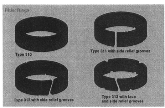
Rider rings support the piston radially and keep the piston body from contacting the cylinder wall. They are also called guide rings, wear bands, or bull rings in different applications.
6.1 Why rider rings are needed
A piston has weight and is subjected to side thrust from connecting-rod angularity, pressure distribution, and motion. In a non-lubricated compressor, the piston body is intentionally smaller than the bore and is held away from the wall by low-friction rider rings.
Typical rider materials include carbon and PTFE-based compounds. Their unit loading is kept low relative to the piston weight and side forces.
6.2 Rider-ring wear
Rider rings are sacrificial components. They wear before the piston contacts the cylinder. Inspect for:
- reduced radial thickness;
- uneven wear around the circumference;
- local melting or smearing;
- embedded dirt;
- cracks or split ends;
- excessive ring-to-groove clearance; and
- evidence of cylinder contact.
Uneven wear can indicate misalignment, crosshead-guide problems, cylinder distortion, or incorrect ring installation.
6.3 Rider-ring installation
Solid PTFE rider bands may be supplied pre-stretched or may require a controlled force-fit installation. The ring must be expanded over the piston without cuts, twists, overheating, or permanent distortion. Installation fixtures and controlled heating may be specified.
The ring ends, gaps, pressure-relief grooves, and axial position must follow the manufacturer’s drawing. Incorrect end-gap alignment can increase leakage or create a weak point.
7. Lubricated piston-cylinder systems
In a lubricated cylinder, oil is introduced to the gas end in a controlled quantity. The oil reduces friction, helps seal microscopic surface irregularities, removes heat, and limits wear.
7.1 Lubrication requirements
The lubricant must be suitable for:
- gas composition;
- discharge temperature;
- pressure;
- ring and cylinder materials;
- expected oil carryover; and
- compatibility with downstream equipment.
Too little oil can cause scuffing, ring wear, and seizure. Too much oil can create deposits, valve sticking, oil carryover, and fire risk in discharge piping.
7.2 Lubricated-cylinder inspection
Inspect:
- lubricator delivery rate;
- distribution points;
- check valves;
- oil viscosity and cleanliness;
- cylinder wall condition;
- ring wear; and
- deposits on valves and heads.
An apparently healthy oil pump does not prove that oil reaches every cylinder point. Blocked quills, check valves, or feed lines can starve one cylinder while another is over-lubricated.
8. Non-lubricated piston-cylinder systems
In a non-lubricated cylinder, the gas end is designed to operate without conventional oil on the bore. The crankcase and frame may still use oil; separation is achieved by a distance piece, packing, scraper, and suitable rod arrangement.
8.1 Construction principles
A non-lubricated gas end commonly uses:
- low-friction piston rings;
- carbon, PTFE, or composite rider bands;
- carefully controlled clearances;
- clean, dry inlet gas;
- a suitable cylinder surface finish; and
- separation from frame lubricant.
The piston outside diameter is smaller than in a lubricated design so that the rider bands support the piston before metal-to-metal contact occurs.
8.2 Cleanliness requirement
Dirt, rust, scale, liquid, and abrasive particles can quickly damage non-lubricated rings and rider bands. The inlet filter, suction piping, separator, drains, and cylinder must be kept clean.
Water can wash away protective films, attack materials, freeze in passages, or cause corrosion. Liquid entering a cylinder may also produce hydraulic impact and break rings or damage the piston.
8.3 Non-lubricated wear pattern
Non-lubricated rings may have a finite wear life that depends on:
- gas cleanliness;
- humidity and condensate;
- pressure ratio;
- piston speed;
- bore finish;
- ring material;
- cylinder temperature; and
- alignment.
A non-lubricated compressor is not maintenance-free. It trades gas-end oil management for tighter cleanliness, material, clearance, and wear control.
9. Piston and cylinder clearances
Clearances allow thermal expansion, ring movement, gas sealing, and safe operation through the complete temperature range.
9.1 Radial clearance
Radial clearance is the space between piston or rider ring and cylinder bore. It must accommodate:
- thermal expansion;
- piston distortion;
- ring thickness and movement;
- rider-ring wear; and
- alignment variation within the specified limits.
Too little radial clearance causes rubbing, scuffing, and seizure. Too much permits piston movement, ring damage, gas leakage, and rider-band overload.
9.2 Piston end clearance
End clearance is the distance between the piston and cylinder head at the end of the stroke. It prevents impact and provides the designed clearance volume.
Too little end clearance can cause:
- piston-to-head contact;
- broken rings;
- head or piston damage;
- noise; and
- sudden seizure.
Too much end clearance increases trapped gas volume and reduces capacity. The gas remaining in the clearance space expands during the suction part of the cycle and occupies volume that could otherwise be filled with fresh air.
9.3 Clearance-volume effect
Clearance ratio may be represented as:
where V_c is clearance volume and V_s is swept volume. Increasing C reduces volumetric efficiency, particularly at higher pressure ratio.
The exact performance effect depends on the compression and expansion processes, valve timing, leakage, and gas properties. A clearance pocket can intentionally reduce capacity, but accidental excessive clearance is a performance defect.
9.4 Measuring end clearance
Measure according to the equipment maker’s method, often with the piston positioned at the end of the stroke and using a specified gauge, lead, or calibrated procedure. Record head-end and crank-end clearances separately for double-acting cylinders.
Check clearance after:
- piston removal;
- piston-rod adjustment;
- crosshead work;
- cylinder or head gasket replacement;
- bearing replacement;
- foundation movement; and
- any change in piston position.
10. Ring and rider-band failure modes
10.1 Ring breakage
Possible causes include:
- insufficient end gap;
- ring flutter;
- brittle or incorrect material;
- cylinder scoring;
- liquid entry;
- excessive temperature;
- ring groove damage; and
- incorrect installation.
Broken pieces can damage valves, cylinder walls, packing, and downstream equipment.
10.2 Ring sticking
Rings may stick in their grooves because of:
- carbon or oil deposits;
- rust or corrosion;
- incorrect groove clearance;
- excessive temperature;
- incompatible lubricant; or
- contaminated gas.
A stuck ring may look intact but leak heavily because it cannot follow the bore.
10.3 Scuffing and seizure
Scuffing occurs when the surfaces lose the required separation and slide with excessive friction. Causes include:
- low or incorrect lubrication;
- excessive temperature;
- inadequate radial clearance;
- misalignment;
- dirt or abrasive particles;
- poor cylinder finish; and
- rider-band failure.
Scuffing can progress rapidly. Stop and investigate before the piston seizes or the cylinder must be replaced.
10.4 Rider-band collapse
If a rider band wears through or melts, the piston body may contact the bore. This creates high friction, scoring, metal transfer, and possible seizure. Uneven rider wear often indicates a mechanical alignment problem rather than normal life alone.
10.5 Excessive ring leakage
Ring leakage causes:
- reduced capacity;
- increased discharge temperature;
- increased power;
- gas blow-by toward the crank end;
- contamination of packing or distance piece; and
- altered interstage pressure.
The compressor may continue running while the leakage gradually worsens. Trend capacity, temperature, and power rather than waiting for a complete failure.
11. Inspection procedure
11.1 Before dismantling
Record:
- suction and discharge pressures;
- interstage pressure;
- cylinder temperatures;
- oil pressure and temperature;
- vibration;
- capacity and power;
- packing leakage; and
- recent changes in gas, speed, or control.
The operating record provides the baseline needed to interpret wear patterns.
11.2 Safe isolation
- Stop the driver.
- Lock out the energy source.
- Isolate suction, discharge, and interstage lines.
- Vent and drain the cylinder and connected equipment.
- Verify zero pressure.
- Isolate cooling water and allow hot components to cool.
- Prevent accidental rotation.
- Follow the maker’s lifting and cylinder-opening procedure.
11.3 Piston inspection
Inspect:
- crown and end faces;
- ring grooves and lands;
- piston-rod attachment;
- hub, nut, and locking arrangement;
- outside diameter and taper;
- cracks and corrosion;
- deposits; and
- signs of head contact.
Use dimensional measurements, not visual judgment alone.
11.4 Ring inspection
Measure:
- free gap where specified;
- installed end gap in the bore;
- radial thickness;
- axial thickness;
- groove clearance;
- ring-to-ring side clearance; and
- wear pattern.
Inspect the cylinder bore for scoring, glazing, taper, out-of-round, and surface transfer. A new ring installed into a damaged bore will not provide a durable repair.
11.5 Rider-band inspection
Measure remaining thickness and check circumferential wear. Inspect groove condition, ring end gap, pressure-relief grooves, and signs of twisting. Confirm that the piston is centred in the bore.
11.6 Reassembly
Before reassembly:
- clean all parts with an approved method;
- confirm ring material and orientation;
- check end gaps and groove clearances;
- stagger ring joints as specified;
- protect ring edges during insertion;
- lubricate only where the design permits;
- restore piston end clearance; and
- torque and lock the piston attachment correctly.
Rotate the machine by hand where permitted and confirm there is no contact or abnormal resistance.
12. Piston condition and operating symptoms
| Symptom | Piston/ring-related possibilities |
|---|---|
| Reduced capacity | Worn or broken piston rings, excessive end clearance, ring sticking |
| High discharge temperature | Ring leakage, piston rubbing, excessive clearance, poor heat transfer |
| Increased power | Ring friction, scuffing, high pressure from leakage or restriction |
| Oil in gas | Excessive cylinder oil, ring wear, packing or scraper failure |
| Cylinder knock | Broken ring, loose piston, inadequate end clearance, liquid entry |
| Vibration | Piston mass change, broken ring, rubbing, misalignment |
| Metal particles | Ring, rider band, piston, cylinder, or bearing wear |
| Interstage pressure change | Ring leakage or altered capacity in one stage |
| Frequent ring replacement | Dirt, poor material, wrong clearance, temperature, alignment, lubrication |
These symptoms overlap with valve and cooler faults. Use pressure, temperature, power, and inspection data together.
13. Worked diagnosis: repeated rider-band wear
Observation
A non-lubricated compressor repeatedly consumes rider bands before the expected maintenance interval. The piston body shows light contact marks on one side of the bore.
Investigation
- Confirm inlet filtration and drain operation.
- Check whether liquid or abrasive particles entered the cylinder.
- Measure piston-rod runout.
- Check crosshead-guide and shoe clearances.
- Measure cylinder bore taper and out-of-round.
- Inspect rider-band groove width and end gap.
- Confirm correct band material and installation.
- Check cylinder temperature and cooling-water flow.
- Review speed, pressure ratio, and operating history.
- Correct alignment or contamination before fitting new bands.
The one-sided contact strongly suggests alignment, guide, or bore geometry rather than ordinary uniform wear. Installing thicker bands without correcting the cause can produce further overload or seizure.
14. Revision questions
- What are the main functions of a compressor piston?
- What is the difference between a piston ring and a rider ring?
- Why are rider rings especially important in non-lubricated compressors?
- Compare one-piece, two-piece, and three-piece piston construction.
- What properties are considered when selecting piston material?
- Why must the piston attachment be positively locked?
- What is the purpose of piston-ring end gap?
- What happens if ring gap is too small?
- What causes ring sticking?
- How does ring leakage affect capacity and temperature?
- What is the purpose of a ring carrier?
- Why can excessive piston-to-cylinder clearance be harmful?
- Why can insufficient radial clearance cause seizure?
- Define piston end clearance.
- How does excess end clearance reduce capacity?
- What causes rider-band uneven wear?
- Why must non-lubricated gas ends be kept clean and dry?
- What is the difference between frame lubrication and cylinder lubrication?
- What measurements should be made during a ring inspection?
- Why should a new ring not be installed in a damaged bore?
- What can cause repeated ring breakage?
- List the symptoms of piston or ring scuffing.
- Why should piston clearance be checked after rod or bearing work?
- What conditions can produce oil in delivered air?
- Describe a safe piston inspection procedure.
15. Self-test scenarios
Scenario A — capacity gradually falls while power rises
Inspect piston-ring leakage, valve condition, cooler performance, and pressure ratio. Worn rings can reduce delivery while increasing re-compression work. Compare cylinder temperatures and interstage pressure to locate the affected stage.
Scenario B — ring breaks shortly after replacement
Check ring material, orientation, end gap, groove clearance, bore condition, cylinder temperature, liquid entry, and installation damage. Replacing the broken ring without identifying the cause is unlikely to produce a durable repair.
Scenario C — oil-free compressor shows metal in the filter
Inspect inlet filtration, rider bands, piston rings, cylinder bore, packing, and distance-piece drains. Determine whether the material is carbon, PTFE, metal, or bearing debris before selecting the repair.
Scenario D — piston contacts the head after overhaul
Stop immediately. Check piston end clearance, rod-to-crosshead position, piston attachment, bearing clearances, gasket thickness, and crankshaft or foundation alignment. Do not continue running to “settle” the components.
16. Summary
The piston assembly controls gas sealing, radial support, pressure transmission, and clearance volume. Piston rings limit leakage; rider rings support and guide the piston; the piston body carries the pressure and inertia load; and the cylinder provides the precision surface in which the assembly operates.
Lubricated and non-lubricated designs use different materials, clearances, and maintenance practices. Non-lubricated service does not remove maintenance; it increases the importance of cleanliness, dry gas, ring material, rider-band condition, alignment, and clearance control.
Correct end clearance prevents impact while excessive clearance reduces capacity. Ring gap, groove clearance, bore condition, temperature, lubrication, and alignment must all be measured during inspection. A durable repair corrects the cause of wear rather than merely replacing the worn ring.