
Governing and Speed Control — Droop, Load Sharing and the Overspeed Trip
How the auxiliary engine's speed is held constant as its load changes, and how two or more sets share load between them.
Key Principles at a Glance 6 points
- The governor only controls the engine speed within prescribed limits; on an accidental sudden load change the speed rises above 15 % of rated before the governor can act, and the time delay in its control means the engine parts may be damaged.
- An overspeed trip is therefore provided to shut down the engine by cutting off the fuel, and it is a protection device, not a speed control.
- The trip is set at about 115 % of normal speed and can be tested by increasing the engine speed with the speed adjuster at no-load condition until the trip cuts the fuel supply.
- The trip must be reset before the engine is restarted: the self-resetting type resets as the engine slows down, while the manual reset type has to be reset by hand, which is a deliberate design choice because it forces someone to look at the engine before it runs again.
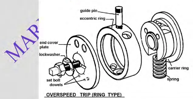
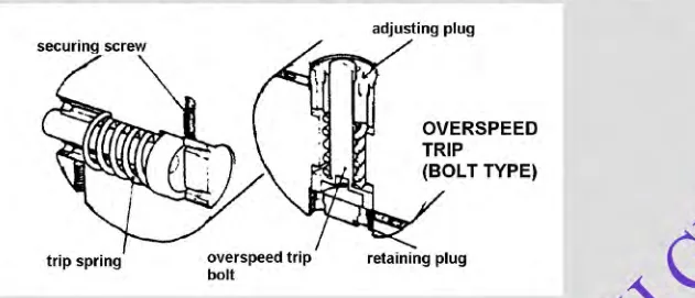
- Two sensing principles are used: the ring type, in which an eccentric ring carried on the shaft moves outwards against its spring as speed rises, and the bolt type, a spring-loaded bolt heavier at one end that centrifugal force swings out to strike a trip lever.
- The governor controls speed; the trip protects the engine when the governor cannot — a governor that has lost its oil, seized its linkage or sheared its drive does nothing at all.
1. What a governor is and what it does
The maker's governor settings, droop figures, load limit settings and overspeed trip setting govern. The overspeed trip is a protection device, not a speed control — it is tested at the maker's interval and never used to regulate speed.
A governor is a device which controls the speed of an engine automatically within prescribed limits. It does its job in two steps:
- Measuring the speed.
- Controlling the amount of fuel supplied to the engine.
Its function is to adjust the rate of fuel supply in such a way as to keep the engine running at a steady speed regardless of the load — to hold a steady speed under all conditions of load.
On a generating engine this is a hard requirement rather than a convenience. The alternator's frequency is locked to its speed, so a speed error is a frequency error, and a frequency error is a fault in the ship's electrical supply. That is why the auxiliary engine's governor is a different animal from a propulsion engine's.
Types of governor:
| Type | How it senses speed | Notes |
|---|---|---|
| Mechanical | Rotating flyweights | Simple; limited by linkage friction |
| Hydraulic | Flyweights acting through a pilot valve onto an oil-operated servo | The standard for a.c. generation |
| Inertia | Inertia of a weighted member during acceleration | Fitted on older slow-speed engines |
| Electronic | Speed pick-ups and a computer, driving an actuator | Modern installations; load sensing possible |
2. The problem a governor has to solve
Understanding why governors are built the way they are makes the rest of this chapter much easier.
A simple mechanical governor must overcome friction in the linkages and exert a control force. These forces act in different directions depending on whether the load is increasing or decreasing. The result is a dead band — a range of speeds over which the governor will not move the fuel at all, because the force it can generate is not enough to overcome the friction. An engine with a dead band hunts, because the governor overshoots each time it does move.
The first fix is to separate the sensing from the work. By having the rotating weights move only a pilot valve, which directs oil to or from a servo, the control force and the friction for the servo are eliminated, and the dead band is removed.
But the simple servo is unstable, because the pilot valve either allows full oil to the servo or drains it, giving full fuel on or off. Stability could be provided by making the valve larger than the servo supply ports — but that would reintroduce a dead band.
The solution is to provide feedback from the fuel linkage, and that feedback comes about with speed droop. This is the key idea in the whole chapter: droop is not a defect to be eliminated. It is the feedback path that makes the governor stable, and it is also what makes load sharing between generators possible.
3. Speed droop
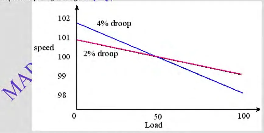
When considering the engine and governor combination, the difference between the no-load speed and the full-load speed is called governor droop.
Speed droop is the decrease in speed taking place when the governor output shaft moves from the minimum to the maximum fuel position in response to load.
What droop does:
- Small droop gives a rapid swing — the governor responds quickly, but the engine's speed moves more for a given load change.
- Large droop gives a slower response to change in speed — the response is gentler but the speed error is larger.
A droop of 2 % means that going from no load to full load the engine slows by 2 % of its rated speed. On a 60 Hz system, full load would be at 58.8 Hz — clearly unacceptable as a steady state, which is why droop is used in a particular way, described in section 5.
The droop adjustment on a real governor
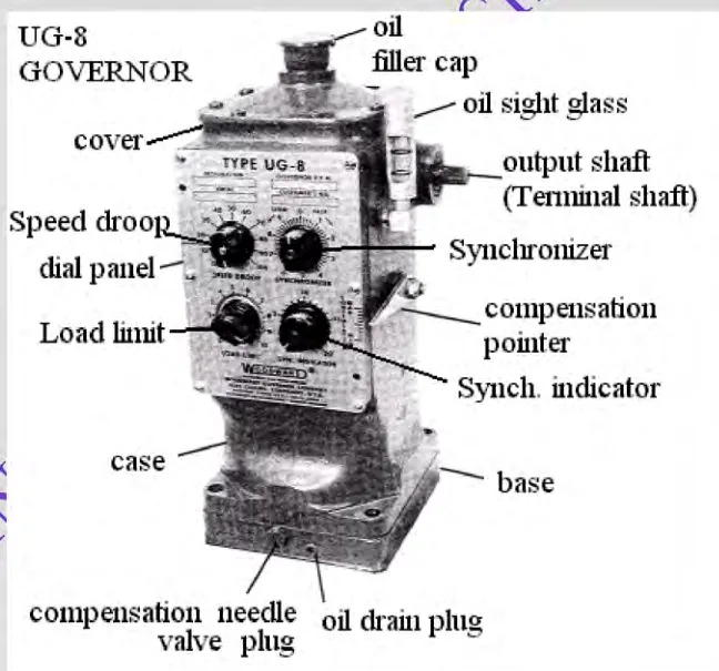
On a UG type governor, the speed droop consists of a control knob, a cam and a linkage which, when preset, varies the compression of the speeder spring as the output shaft rotates.
- Increasing the fuel reduces the speeder spring compression, and in turn the governor speed setting. So the unit gradually reduces its speed as load is applied. This relationship between load and speed acts as resistance to load changes when the unit is interconnected with others, either mechanically or electrically.
- Reducing droop to zero allows the unit to change load without changing speed. Normally zero droop is set on units running alone — a single set on the board should hold frequency exactly.
- On interconnected units, set the least amount of droop possible that still gives satisfactory load division.
One warning about the scale. Marks on the droop adjustment scale on the dial panel are reference numbers only and do not represent droop percentages. Thus the 100 mark does not represent 100 % droop — it represents the maximum droop percentage available on that particular governor model.
Compensation — droop that is temporary
The use of temporary speed droop to prevent over-correction of the fuel supply is called compensation. It requires two actions:
- Droop application — as the fuel supply is changed.
- Droop removal — as the engine responds to the fuel change and returns to its original speed.
Compensation is simply another word for a temporary speed droop characteristic. The compensation system creates a small temporary change of speed setting with governor output shaft movement, to produce a stabilising effect. That change of speed setting is followed by a slow return of the speed setting to its original value.
On a UG governor the compensation system comprises:
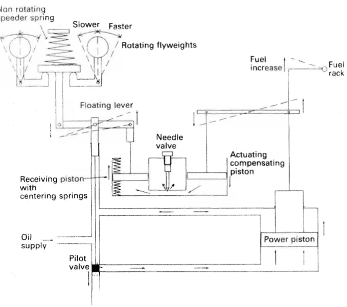
- A large dashpot compensation piston, connected to the governor output shaft by a compensation adjusting lever, with a pivotable fulcrum riding on that lever. Changing the fulcrum's position controls the amount of stroke available to the large piston.
- A small dashpot compensation piston, connected through a floating lever to the pilot valve plunger and the speeder.
- A needle valve, which is a variable orifice controlling the flow of oil between both pistons and the sump. The needle valve setting controls the rate at which the small piston returns to normal.
Compensation must be properly adjusted to the particular engine and load to provide stable operation. The fulcrum position sets how much temporary droop is applied; the needle valve sets how quickly it is removed.
Hunting
Hunting is caused by the unavoidable time lag between the movement of the governor and the movement of the engine's response. The governor moves the fuel; the engine takes time to respond; the governor sees the result too late and over-corrects; the cycle repeats. Compensation exists to damp exactly this.
An isochronous governor is a constant speed governor — one able to maintain exactly constant speed without hunting. It is a governor that has both proportional and reset action. The "reset" is what removes the steady-state speed error that a purely proportional (droop) governor would leave.
4. How the governor works, step by step
It is worth following the sequence through, because it shows why every part of the governor exists.
Steady state
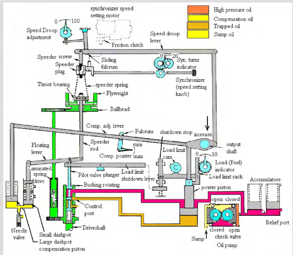
When the prime mover is running on speed, the flyweights are in a vertical position for normal steady-state operation. The pilot valve plunger is centred over the control port of the rotating bushing, and the control land stops the flow of pressure oil through the bushing control port. There is no movement of the power piston and no movement of the governor output shaft.
Decrease in load
A decrease in load creates an increase in speed, because the same fuel setting is now driving less load. The sequence is:
- As speed increases, the centrifugal force of the flyweights increases and becomes stronger than the force of the speeder spring.
- The flyweights tip outward and raise the speeder rod and the right end of the floating lever.
- This raises the pilot valve plunger, opening the control port in the rotating bushing. Oil is released from the bottom of the power piston to the sump.
- Pressure oil on the top side of the power piston moves it downward, rotating the governor output shaft in the decrease fuel direction.
- Linkage from the governor output shaft lowers the compensation adjusting lever, which rotates at the fulcrum, raising the large dashpot compensation piston.
- Suction is thus applied to the chamber of the small dashpot compensation piston, lowering the left end of the floating lever.
- This lowers the pilot valve plunger, closing the control port.
- As sump oil flows through the needle valve into the dashpot assembly, the small piston is returned to its normal centred position by the compensation spring, at the same rate as the speeder rod. This keeps the pilot valve plunger in its centred position.
- The control port in the rotating bushing is kept closed by the land on the pilot valve plunger.
- This stops the governor output shaft and power piston movement in the new, decreased fuel position — the position needed to run the prime mover at the selected speed setting with the new load.
Increase in load
An increase in load causes a decrease in speed, and the sequence runs in the opposite direction:
- The flyweights move inward, lowering the speeder rod.
- The pilot valve plunger is lowered, admitting oil to the underside of the power piston.
- The power piston is forced upward by the pressure oil acting on the large lower surface area of the power piston, and the output shaft rotates in the increase fuel direction.
- Linkage from the output shaft lifts the compensating adjusting lever, rotating the fulcrum and lowering the large dashpot compensation piston.
- Pressure oil is applied to the bottom of the small dashpot piston, raising the left end of the floating lever.
- This raises the pilot valve plunger, closing the control port.
- As the pressure oil flows through the needle valve, the small piston returns to its normal centred position at the same rate as the speeder rod.
- The control port is kept closed, and the output shaft stops in the new increased fuel position.
In both cases, the compensation system operates in opposite directions. The amount of movement of the large piston is controlled by the fulcrum adjustment; the rate at which the small piston returns to normal is controlled by the needle valve adjustment.
The power piston and the accumulator
Two components are worth naming because they appear in every description.
The power piston moves the governor output shaft to the increase or decrease fuel position. It is a differential type, with oil pressure on both sides. The bottom of the piston has a larger area than the top, so less oil pressure is needed on the bottom than on the top to hold the piston stationary. If the oil pressure is the same on both sides, the piston moves up to rotate the output shaft in the increase fuel direction; it moves down only when oil under the piston is released.
The accumulator stores oil under pressure for the operation of the governor. It consists of two spring-loaded pistons, and it also acts as a pressure relief valve if the oil pressure becomes too high: when the pressure exceeds about 120 psi on a UG-8, or 150 psi on a UG-12, oil is released back to the sump through a relief port in each cylinder.
The oil pump is a positive displacement gear pump driven from the engine, drawing from the governor's own self-contained sump, and arranged with four check valves so that it will work in either direction of rotation.
5. Load sharing between generators
This is where droop earns its place, and it is the part of governing that has to be understood rather than memorised.
Why two isochronous governors cannot share load
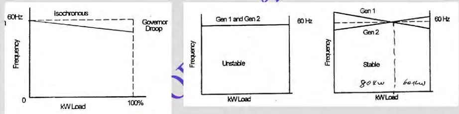
Speed droop helps in stable, parallel operation of machinery.
If both governors are isochronous, there is no crossing point. Load swings from one machine to another. Hence the system is unstable.
The reasoning is simple once seen. An isochronous governor holds its machine at exactly rated speed whatever the load. So if two such machines are paralleled, both are trying to hold exactly the same speed. There is no speed at which the two are in equilibrium — any small disturbance makes one machine take the whole load and the other shed it, and the load swings back and forth. Nothing in either governor resists the transfer, because neither governor's speed changes with load.
With droop, each machine's speed falls as its load rises. The two droop lines cross at one point, and that crossing point is the stable operating point. If one machine takes more load than its share, its speed falls, and the other — whose speed is now higher — takes more load. The system self-corrects.
How to set a real installation
For AC generating units tied in with other units, set the droop sufficiently high — reference numbers 30 to 50 — to prevent interchange of load between units.
If one unit in the system has enough capacity, set its governor on zero droop, and it will regulate the frequency of the prime mover system. If the capacity is not exceeded, this unit will handle all load. The machine on zero droop is the one holding the frequency; the others run on droop and take load in proportion.
The controls used are different for the two roles:
- Operate the synchroniser of the governor with zero droop to adjust the system frequency.
- Operate the synchronisers of the governors that have speed droop to distribute load between units.
That is the rule worth carrying away: on a paralleled board, the synchroniser on the zero-droop machine sets frequency; the synchronisers on the droop machines shift load between them.
It is usual to have one engine governor as the master and the others as slaves, although the practicalities vary with the installation.
Governor travel and the load limit
A governor output shaft does not use its full travel for load. Normally about two-thirds of the full governor travel covers no load to full load. The rest is:
- Overtravel to ensure the prime mover's stops are reached.
- Travel required to accelerate the prime mover.
- Travel required to decelerate or shut the prime mover down.
The load limit control exists to stop the governor from taking the engine beyond its safe output. Its purpose is to hydraulically and mechanically limit the load by restricting the travel of the governor output shaft in the increase fuel direction, and consequently the amount of fuel supplied to the engine. It consists of an indicator disc geared to a load limit rack, with a control knob attached to the load limit cam. The load is limited mechanically by positioning the load limit knob: when the load indicator reaches the preset point, the pilot valve plunger is lifted, stopping any further increase in fuel.
The load limit control may also be used for shutting the engine down, by turning it to zero. Doing so turns the load limit (shutdown) strap down, pivoting the shutdown lever about its fulcrum and lifting the pilot valve plunger. That releases oil from under the power piston, and the pressure oil acting on the top of the piston forces it downward, rotating the governor output shaft to minimum fuel and causing the prime mover to shut down. This is why the load limit is also the manual shutdown on many governors.
6. Auxiliary engine and main engine governors are different machines
This comparison is worth knowing because it explains almost every design decision in an auxiliary engine governor.
| Main engine governor (e.g. PGA) | Auxiliary engine governor (e.g. UG-8) | |
|---|---|---|
| Duty | Variable speed | Constant speed |
| Speed range | Control from lowest to maximum speed limit | Held at one speed |
| Droop | No speed droop required, unless twin engines are coupled to a single shaft | Speed droop required |
| Oil pump | Can deliver oil for both engine directions | Oil pumps for one engine direction |
| Speed setting | Remote speed setting, pneumatic | Electric drive controls the speeder spring setting |
| Character | — | Almost isochronous |
The UG-8 governor is used for auxiliary engines and controllable pitch propeller installations, with other models in the family being the UG-7 and UG-10. It uses 120 psi oil pressure for operation.
The main engine governor has to work over a whole speed range and follow telegraph orders, so it is a variable speed device with remote pneumatic setting. The auxiliary engine governor has to hold one speed and share load, so it is an almost-isochronous device with a droop characteristic and an electric speeder motor that the switchboard can drive.
The Woodward governor
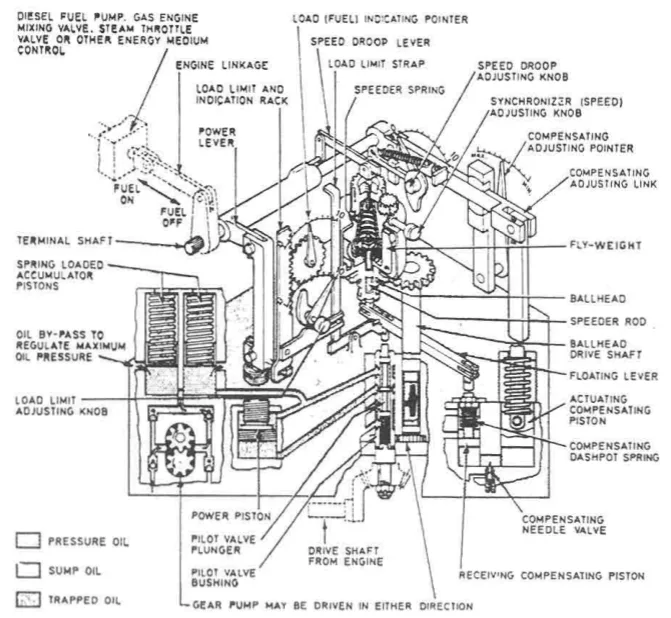
When used for alternating current power generation, a diesel engine is normally fitted with a hydraulic governor. It incorporates a centrifugal speed sensing device — spring-loaded flyweights — controlling a suitably damped oil-operated servo-cylinder through a pilot valve. The governor has adjustable speed droop and load limit controls, and a split field, electric motor-operated speeder gear to facilitate remote alteration of engine speed setting from the switchboard, which alters the spring pressure usually through a screwed rod.
The Woodward governor is a commonly fitted example. It has:
- A gear pump driven from the engine camshaft, supplying hydraulic oil first to accumulator pistons, under which is a bypass to regulate maximum pressure.
- One branch of the oil supply acting on top of the power piston, the pressure tending to turn the terminal shaft to shut off fuel.
- The other branch supplying the pilot valve, which is operated by the linkage from the flyweights.
The fail-safe sense of this arrangement is worth noting: if the governor loses oil pressure, the pressure on top of the power piston is lost and the piston moves to the shut-off position. The engine stops rather than runs away.
7. Electronic governors
Modern auxiliary engines increasingly use electronic governing. The principles are the same — speed sensing, a pilot valve, a servo — but the sensing and the computation are electronic and the servo is an electro-mechanical actuator.
The basic task of an electronic governor is to regulate the shaft speed of the engine to which it is attached. That means it must be able to translate the speed commands given by the operator — for example, by means of a remote control system — into adequate movement of the fuel rods controlling the injection of fuel into the engine cylinders. The engine in question may be anything from a two-stroke slow-speed propulsion diesel to a four-stroke, medium-speed generator diesel.
Typical components:
- Power unit, located in the engine control room. It contains all the electronics and a computer required to translate the signals received from the control unit, the ECR speed setting handle, the engine remote control system and external sensors into a movement of the actuator. The actuator movement causes the engine fuel pumps to inject the correct amount of fuel.
- Control unit, also in the ECR, providing the engine staff with a means of communication with the governor, plus facilities for diagnosis, test and simulation. It displays messages in plain language, not computer code, and carries light emitting diodes which instantly show the overall condition of the governor.
- Actuator, located at the engine. This is the electro-mechanical device which converts an electrical control signal into mechanical action, and it is the device that actually exerts the required force on the fuel rack. The correct actuator depends on the engine type: the size depends on the force and the inertia of the fuel rack — that is, on the engine make, the number of cylinders and the bore. The choice is made in collaboration with the engine manufacturer. Actuators contain a rugged brushless servo motor for very fast response, and a high torque braking system able to lock the actuator during specific fault conditions. Gearboxes are sealed and require no periodic maintenance, and the actuator is protected against overload.
- Tacho system, located very close to the engine turning wheel. It comprises two induction pick-ups mounted in a bracket, each acting as the backup for the other, sensing the passing of the turning wheel teeth. Only one pick-up is necessary to sense engine speed; the second is redundancy.
- Scavenging air pressure sensor, where engine output power is a function of scavenge air pressure.
Load sensing
In a load sensing electronic governor, load sensing and speed sensing are independent of each other. The load change is sensed prior to the speed change.
The purpose of load sensing is to correct the fuel supply to the prime mover before a speed change occurs. This helps in improving accuracy, and is achieved by an electronic computing circuit, which controls a solenoid-operated pilot valve in a direction proportional to the load change. In an auxiliary engine, the load measurement is the electrical output — the alternator's own output is the load signal.
The advantage over a pure speed-sensing governor is that the correction is made before the speed has had time to fall, so the frequency dip on a load change is smaller.
Fuel limiting
An electronic governor can also limit the fuel in ways a mechanical governor cannot, protecting the engine from being asked for more than it can deliver:
- Torque fuel limiter — limits fuel according to the torque the engine can take.
- Manual fuel limiter — a fixed maximum set by the operator.
- Charge air fuel limiter — limits fuel according to the scavenge air pressure available, so that the engine cannot be given more fuel than there is air to burn it. This prevents fuel from increasing rapidly and avoids overload.
The governor may run in RPM mode, power mode or index mode, and in an auto select setting will choose between them: power mode in rough weather and RPM mode in calm weather, with the change over criterion at about sea state 3. In power mode the governor maintains approximately constant shaft power, which reduces wear on the fuel racks and the actuator; in index mode it maintains a fixed fuel index, used mainly when measuring engine performance by cylinder pressure indication. RPM control is retained in every mode if the speed becomes too high.
Electronic governor on a main engine
Where an electronic governor is fitted to a propulsion engine, its components include the console with control unit, the bridge telegraph, the power unit, the actuator, the safety system, the scavenge air pressure sensor and the tacho pick-ups, all tied together with the remote control system.
8. What the auxiliary engine's governor has to achieve
The performance requirements for a generating set's governor are written as figures, and they are the benchmark against which governor condition is judged.
Speed — the governor's responsibility:
| Requirement | Limit |
|---|---|
| Speed change on a 25 % change in full rated load | Not more than 2.5 % |
| Recovery within 2 seconds | To within 1 % of final steady speed |
| Recovery within 4 seconds | To within 0.5 % of final steady speed |
Voltage is not the governor's business. It is the automatic voltage regulator's, and the figures for it belong with the AVR in Chapter 9. The split matters: the governor controls frequency (speed) and the AVR controls voltage, they are separate devices with separate failure modes, and a frequency fault and a voltage fault are therefore different faults with different causes.
9. The overspeed trip
The governor only controls the engine speed within prescribed limits. When there is an accidental sudden load change — for example from full load to no load — the engine speed becomes too high, above 15 % of rated speed, before the governor can act. Because of the time delay in the governor's control, the engine parts may be damaged.
An overspeed trip is therefore provided to shut down the engine by cutting off the fuel. It is a protection device, not a speed control, and it acts only when the governor has already failed to control.
The trip is set at about 115 % of normal speed. It can be tested by increasing the engine speed with the speed adjuster at no-load condition; the overspeed trip should then cut out the fuel supply at 115 % of normal speed.
The trip must be reset before the engine is restarted. Some types are manual reset and some are self-resetting; the self-resetting type is reset by the engine slowing down, while the manual reset type has to be reset by hand — which is a deliberate design choice, because it forces someone to look at the engine before it runs again.
Two sensing principles are used:
- The ring type overspeed trip, in which an eccentric ring carried on the shaft moves outwards against its spring as speed rises, and trips a latch when it has moved far enough.
- The bolt type overspeed trip, which consists of a spring-loaded stainless steel bolt which, due to its special design, is heavier at one end than the other. The rotary motion of the engine shaft tends to move the bolt outwards, while the spring retains it in its normal position. At the trip speed the bolt overcomes the spring, moves out, and strikes a trip lever.
Why the trip is fitted although a governor is already fitted is the single most important thing to understand about it. The governor controls speed; the trip protects the engine when the governor cannot. A governor that has lost its oil, or whose linkage has seized, or whose drive has sheared, does nothing at all — and a generating engine that loses its load and its governor together will accelerate until something breaks. The overspeed trip is the last line of defence, and it is the reason the trip is tested rather than assumed.