
What the Auxiliary Engine Is — Why It Is a Four-Stroke Medium-Speed Machine
Establish what the auxiliary engine is, what distinguishes it from the main propulsion engine, and why it is almost always a four-stroke medium-speed machine.
Key Principles at a Glance 5 points
- The auxiliary engine exists to make electrical power, and it is almost always a four-stroke medium-speed machine because that is what suits a constant-speed generator drive.
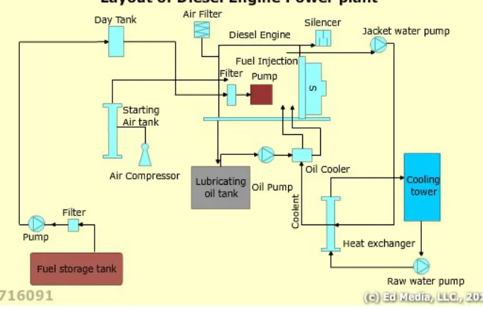
- The cooling water is normally cross-connected with the main engine, which lets the main engine be kept warm in port from the heat the auxiliary engine needs to get rid of anyway.
- To let an auxiliary engine be run in dry dock, a connection is customarily arranged from a double bottom or peak tank.
- On installations with a waste-heat boiler the auxiliary engine's exhaust gas is passed through an exhaust gas economiser to raise steam, and the economiser must be taken off load when the engine stops or the coils will be damaged.
- In a periodically unmanned machinery space the engine is expected to look after itself: automatic changeover to a standby machine, automatic starting and stopping as the load rises and falls, synchronising, breaker closure and load sharing are all normally automatic.
1. What the auxiliary engine does
The engine maker's instruction book, the classification society rules, the PMS and the Chief Engineer's orders override these notes. No engine is started without the pre-start checks completed and clearance given.
An auxiliary engine is a diesel engine whose job is to turn an alternator, and through it to supply the ship with electrical power. It is the prime mover of a generating set. The term prime mover means simply the machine that provides the power in the first place — the diesel burns fuel inside itself, the burning gases act on the piston, and the resulting mechanical energy is handed to the alternator, which converts it to electrical energy.
That is the whole arrangement: a diesel engine and an alternator, coupled together, on a common bed.
The auxiliary engine may also be coupled to drive other machinery directly — a large pump, a bow thruster, a cargo pump — but the generator duty is by far the most common and is the duty this set of chapters is written around.
2. Where the ship's electrical power comes from
The auxiliary engine is not the only possible source of electrical power, and it is worth knowing the alternatives because the auxiliary engine's role on a particular ship is defined by which of them are fitted.
| Source | How it works | When it is used |
|---|---|---|
| Auxiliary diesel generating sets | Medium- or high-speed four-stroke diesels coupled to alternators | At all times, and always in port and manoeuvring |
| Main-engine driven generators | An alternator driven from the propeller shaft, a gearbox or the engine itself | At sea, where the main engine runs steadily |
| Exhaust gas or steam turbo-generators | A turbine driven by steam raised in a waste-heat boiler in the main engine exhaust | At sea, on large slow-speed installations |
| Emergency diesel generating set | A small independent set above the bulkhead deck | Only when the main power fails |
The diesel generating set is the one that must work. The shaft generator and the turbo-generator only work when the main engine is running at a steady speed; the auxiliary engines carry the ship in port, in manoeuvring, and whenever the main engine stops. This is why the auxiliary engine is the machine the engineer spends most of their time with.
There is also a cost argument that shapes modern practice. Diesel generating sets are expensive to run — fuel cost and maintenance both — and running them continuously at sea is wasteful if a cheaper source is available. This has driven two developments: running the auxiliary engines on residual fuel rather than distillate wherever the engine is designed for it, and fitting a shaft generator so that the auxiliary engines can be shut down at sea.
Running the auxiliary engine on residual fuel
Burning low-grade residual fuel in a medium-speed auxiliary engine is common and, if it is done badly, disastrous. Fuel bunkered for a slow-speed main engine may be of too poor a quality for an auxiliary even where the engine was designed for heavy fuel operation. Catalytic fines — abrasive particles based on aluminium and silicon — are the particular danger; they cause surface damage to injector nozzles and can wreck the fuel injection equipment.
The remedy is the same as for any heavy fuel installation: the fuel must conform to the specification in the engine's instruction book, and it must be treated before it reaches the engine. The fuel system, the treatment arrangements and the fuel blender are in Chapter 8, which owns the fuel side.
3. Why the auxiliary engine is a four-stroke
Marine diesels divide into three speed bands, and the band a machine belongs to tells you what it is for.
| Band | Speed | Typical duty |
|---|---|---|
| Slow speed | up to about 300 rpm | Large two-stroke crosshead engines driving the propeller directly |
| Medium speed | about 300 – 900 rpm | Four-stroke engines driving generators, or the propeller through reduction gearing |
| High speed | above about 900 rpm | Small four-stroke engines; road vehicles, boats, small craft |
The engines that turn the propeller of an ordinary ship are slow-speed two-strokes. The engines that provide auxiliary power are four-stroke medium-speed machines. That is the distinction this chapter is about, and it is worth being clear why the split falls that way.
Four-stroke engines are favoured where headroom is limited, because they are more compact for their power than a two-stroke of the same output. This matters on ferries and passenger vessels, and it matters in the machinery space of any ship where the auxiliary engines have to be fitted in around everything else.
The trend towards diesel-electric propulsion reinforces the choice. In a diesel-electric ship the engines no longer have to be aligned with reduction gearing and shafting; they can be placed wherever there is space, and they all drive alternators. That is exactly the duty a four-stroke medium-speed engine is good at.
Two further points follow from the higher running speed.
Medium-speed engines have a higher power-to-weight ratio than slow-speed two-strokes. For the same weight you get more power, which is why they are used where the machinery must be light and compact.
But the higher speed means shorter maintenance intervals. More revolutions per hour means more wear per hour. The largest four-stroke engines now deliver just over 2,000 kW per cylinder, but they earn that output with more frequent attention than a slow-speed engine of the same power.
What four-stroke means for the engine's construction
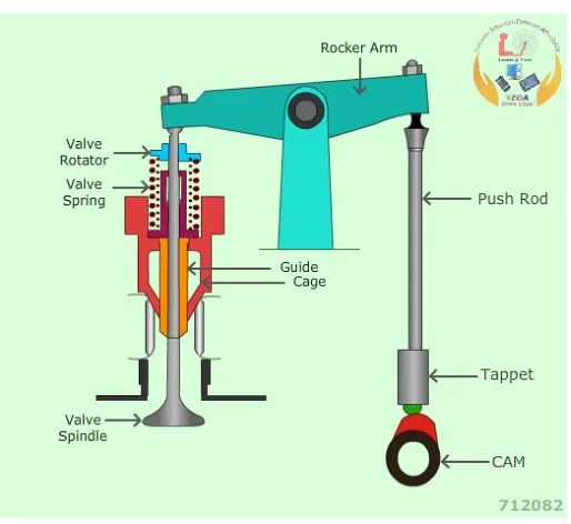
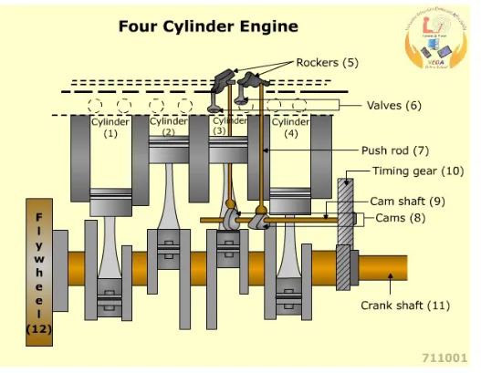
The four-stroke cycle needs air inlet and exhaust valves in the cylinder head, because the cylinder cannot be scavenged through ports as a two-stroke's is. The cycle is:
- Induction — the inlet valve opens and air is drawn in as the piston descends.
- Compression — both valves shut and the air is compressed, which raises its temperature.
- Power — fuel is injected into the hot air, it ignites, and the expanding gases drive the piston down.
- Exhaust — the exhaust valve opens and the burnt gases are pushed out as the piston rises.
There is one power stroke every two revolutions of the crankshaft, against one per revolution for a two-stroke. That is the price of the four-stroke, and it is paid back in better scavenging, lower thermal loading and better fuel economy.
The most important structural consequence for the auxiliary engine is this: the four-stroke is a trunk piston engine. The piston is directly connected to the connecting rod by a gudgeon pin, and the connecting rod works directly on the crankshaft. There is no crosshead, no piston rod and no stuffing box. The space below the piston is the crankcase, and it is sealed from the combustion space only by the piston rings.
That single fact changes everything downstream:
- The crankcase is part of the engine's working space, so it must be vented, it must have relief valves, and it is where a crankcase explosion would occur.
- The cylinder is lubricated from the crankcase, by splash and by oil thrown from the bearings, rather than by a separate cylinder lubricator. There is no separate cylinder oil and no separate cylinder oil system on a small auxiliary engine.
- The whole engine is shorter and lighter, because there is no crosshead guide and no piston rod.
In-line and Vee
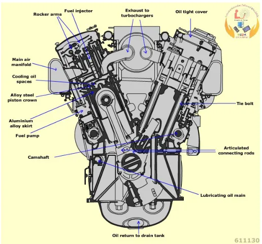
Auxiliary engines are built in two forms. An in-line engine has all its cylinders in a single row along the centre of the block. A Vee engine has two banks of cylinders set at an angle to each other, sharing one crankshaft.
The Vee form fits greater power into a shorter, more compact space, which is usually what matters in a machinery space. It also needs careful balancing, and the firing order is arranged so that the two banks share the load evenly.
4. How the engine is put together
The components of an auxiliary engine divide into two groups, and it is worth keeping the division in mind because it decides which parts wear and which do not.
Fixed components — the bedplate, the frame and cylinder block, the cylinder liners, the cylinder heads and covers, the main bearing housings. These locate everything else and carry the loads.
Moving components — the crankshaft, the connecting rods, the pistons and rings, the gudgeon pins, the camshaft, the push rods, the rocker arms and the valves. These are the parts that wear, the parts that are measured at overhaul, and the parts that fail.
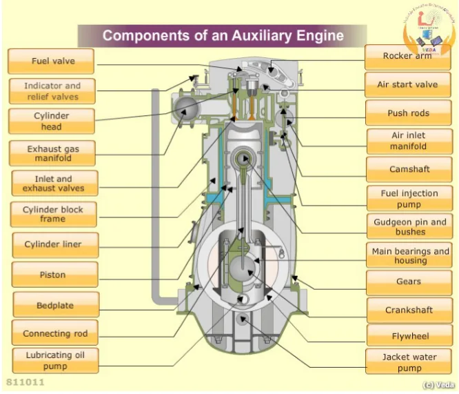
The individual components are described in the chapters that follow: the structure in Chapter 3, the moving parts in Chapter 4, and the valve gear and fuel injection equipment in Chapter 5.
5. The shape of the machine — a typical medium-speed engine
It helps to have one concrete engine in mind. A representative medium-speed auxiliary engine — the Allen S12 type, in-line, built in four, six, eight and nine cylinder versions, with a Vee equivalent designated VS12 in twelve and sixteen cylinders — is put together like this:
- A deep-section cast iron bedplate and a cast iron A-frame of monobloc construction, flanged and bolted together.
- Thin-wall, steel-backed, white-metal or aluminium-tin lined main bearings in the bedplate.
- An additional bearing to carry the combined loads of the flywheel and part of the weight of the generator.
- Access doors front and back, those on the back fitted with crankcase explosion relief valves.
- A one-piece alloy steel crankshaft, slab-forged, oil-hardened and tempered, with a solid half coupling forged integrally to carry the flywheel.
- Balance weights bolted to the crank webs where required. A four-cylinder engine with cranks at 180° needs secondary balancing gear.
- H-section steel connecting rods, bored to carry oil to the gudgeon pin bush.
- In this style of construction it is necessary to lift the A-frame if the crankshaft is to be removed. Some designs use a C-frame arrangement which allows the crankshaft to be taken out sideways.
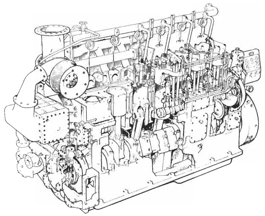
Note the last point, because it is the difference between a medium-speed auxiliary engine and a slow-speed main engine. The frame of a medium-speed engine is usually a single monobloc casting — stronger and stiffer for its size, but it means the crankshaft comes out the top, or the frame comes off first. The comparison with the separate, tie-rod construction of a slow-speed engine is drawn in Chapter 3, which owns the engine structure.
6. The engine as part of the ship
Two connections matter beyond the engine itself.
The cooling water is normally cross-connected with the main engine. In ships with diesel main propulsion, cross-connections between the main and auxiliary engine jacket water systems are common. This lets the main engine be kept warm in port from the heat in the auxiliary engine jacket water — which is exactly the heat the auxiliary engine needs to get rid of anyway. To let an auxiliary engine be run in dry dock, a connection is customarily arranged from a double bottom or peak tank.
The exhaust is used. On installations with a waste-heat boiler, the auxiliary engine's exhaust gas is passed through an exhaust gas economiser to raise steam, in the same way as the main engine's. The economiser must be taken off load when the engine stops, and brought on load carefully when it starts, or the coils will be damaged.
The engine is also, in a periodically unmanned machinery space, expected to look after itself. Automatic changeover to a standby machine, automatic starting and stopping as the load rises and falls, synchronising, breaker closure and load sharing are all normally automatic. That capability is what the next chapters describe.