
The Valve Gear and Fuel Injection — Valves, Camshaft Drive, Pumps and Injectors
How air gets into the cylinder, how the exhaust gets out, how the valves are operated, and how fuel is metered and injected.
Key Principles at a Glance 7 points
- The fuel injector is fitted on the cylinder head by an integral flange in the holder and two studs with distance pieces and nuts.
- The mating surfaces between the valve body and the nozzle are ground and lapped to form an oil pressure-tight seal, and the nozzle and needle are lapped together as a pair and cannot be replaced individually.
- Between the two lowest O rings the leak-off oil from the fuel valve is led out, and a sudden increase in leak-off means the nozzle needle is worn or the valve is not seating.
- The injector has two functions: to open and close the passage of fuel to the combustion chamber, and to convert the high-pressure oil from the pump into a fine spray of the desired pattern.
- The spray pattern matters as much as the quantity — a dribbling or off-centre nozzle puts fuel on the liner wall instead of into the air, causing liner wear, carbon build-up and incomplete combustion.
- The nozzle assembly and the fuel valve are cooled by the injected fuel itself, which is why a hot engine should not be stopped abruptly with a hot nozzle.
- When fuel pump delivery ceases there should be a sharp drop in pressure, because that is what makes the nozzle valve close smartly with an instant cut-off of the spray; a slow fall away gives dribble, late burning and a coked nozzle.
1. The valves
The maker's valve timing figures, tappet clearances, injection pump settings and injector test pressures govern. Timing is checked against the flywheel marks, never set by eye.
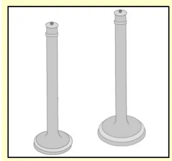
Air inlet and exhaust valves of the mushroom type are used in four-stroke engines. They sit in the cylinder head, they open into the cylinder, and they are held shut by springs.
Why the inlet valve is larger than the exhaust
Inlet valves are of larger size than exhaust valves, to handle the large flow rate of fresh air. The exhaust valve is made smaller for three reasons:
- The exhaust valve opens against a higher pressure within the cylinder. At the end of the power stroke there is still pressure in the cylinder, and the valve has to be pushed open against it. A smaller valve presents a smaller area for that pressure to act on, so it needs less force to open.
- Unlike the inlet valve, the removal of the gases through the open exhaust valve is assisted by the exhaust gases themselves. The gas is trying to get out; the air has to be pulled in.
- Being smaller assists in keeping it cool, which is important as the exhaust valve operates at higher temperatures.
Point 3 is the one that matters most in service. The exhaust valve runs red hot, and heat is the enemy. A smaller valve has less area to absorb heat from the gas and a shorter path to conduct it away.
How the valves are made and held
- The valve spindles are subjected to high temperatures, and are therefore made of a material with good creep resistance. Exhaust valves in particular are usually faced with a hard stellite coating on the valve lid and seat.
- Both valves open into the cylinder, so that the high gas pressure in the cylinder holds the lids firmly against their seats. The cylinder pressure helps to keep them shut; it does not try to blow them open. The springs only have to keep the lids seated during the low pressure part of the cycle.
- Two springs are fitted for each valve, to avoid axial vibration. The two springs have different natural frequencies, so they damp each other. There is a second benefit: even if one spring fails, the valve does not fall into the cylinder and damage the other components.
- The valve is held to the cylinder head by a spring and cotter arrangement. To remove the valve spindle, the spring is depressed using a special tool and the cotters are taken out.
Valve rotation
Exhaust valves are designed to rotate in service. The reasons are:
- To prevent uneven temperatures — and the consequential deposits of salts of sodium and vanadium — so that the valve does not distort and leak by.
- To help dislodge any build-up of deposits on the valve and seat which might prevent the valve closing properly, and lead to "hammering" of the seating faces.
A mechanical method is generally used, and this is the roto cap. The rotator sits in the spring retainer and turns the valve a few degrees each time it opens, driven by the valve spring's own action.
Caged exhaust valves
On some medium-speed engines the exhaust valve is a separate unit. Water cooling passages are provided to cool the exhaust valve, and the valve sits in its own cage. The advantage is that when the exhaust valves are overhauled, the valve is removed without opening the entire cylinder head. On a large medium-speed engine that can save many hours of work and a great deal of disturbed jointing.
Where the engine burns heavy fuel oil, the exhaust valve seats are cooled to prevent high temperature corrosion due to sodium and vanadium in the fuel. Those elements form ash compounds which attack the metal at high temperature, and cooling the seat keeps it below the temperature at which the attack is rapid.
Valve burning
Once an exhaust valve does not seat correctly, the high-pressure burning gas passes across the faces of the valve and seat during the power stroke. What follows is a runaway:
- The gas leaking past raises the temperature of the valve and seat in that area, weakening the material and distorting the surfaces.
- The velocity of the burning gas erodes the surface, allowing more gas to leak by.
- The temperature in that area rises further, leading to further burning and greater distortion.
The chain only stops when the valve is replaced. The first indication of a valve burning out is a rise in the exhaust temperature, which will then increase rapidly together with a loss of power from the unit. The temperature rise is the early warning, and it is worth acting on while it is still only a temperature rise.
2. The valve operating gear
The rocker arm
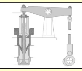
The rocker arm has one end on the valve stem and the other on the push rod, through a hardened steel roller where it meets the push rod. It consists of a housing or bracket that supports a bush, with a pivot pin resting inside the bronze bushing. The brackets are bolted to the cylinder head.
The rocker arm transmits the cam motion to the valve stem by a push rod. It is pivoted at its centre, so the motion of the push rod is reversed and passed to the valve. In a four-stroke engine the rocker arms open and close the inlet and exhaust valves, but there is no direct connection between the two — the rocker simply sits on the valve, and the push rod moves the rocker.
Lubricating the rocker gear
Depending on the engine, the rocker arms are lubricated either by an independent lubricating system or by the main lubricating system.
The usual arrangement is elegant: the rocker-shaft feed is connected to a hollow tappet screw, so oil flows directly into the push rod's bowl-shaped seat, overflows, and drains down the push rod, lubricating the cam follower on the way. The valve-stem end of the rocker arm contains a horizontal hole drilled along it, so that oil is fed directly to the valve and spring assembly.
While the engine is running, a visual check can be made to confirm the flow of oil into the rocker arm. The flow rate will change if the clearances have changed. If the flow is less than it should be, check the feed line filters — a partly blocked rocker feed filter starves the whole valve gear.
The push rods
The push rod transmits the action of the cam to the valve stem through the rocker arm. It translates the rotary motion of the cam into the reciprocating motion of the valve.
- Push rods are hollow, to obtain stiffness without unnecessary weight.
- The lower end carries a follower of mushroom shape, which rides on the cam.
- The upper end has a rounded head which fits into a cup on one end of the valve rocker arm.
Tappet clearance
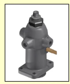
Tappet clearance is the clearance between the rocker arm and the point where it rests on the valve. It is provided for two reasons:
- Positive closing of the valves.
- Thermal expansion of the valve.
As the valve and its operating gear heat up in service, the clearance between the rocker arm and the valve stem decreases. If insufficient clearance is allowed, the valve will be prevented from seating. Usually both surfaces are flat.
What the clearance does to timing:
| Clearance | Effect on the valve |
|---|---|
| Too large | Opens late and closes early — the valve is open for less time |
| Too small | Opens early and closes late — the valve may not seat at all |
The general clearance is 0.3 mm to 1.5 mm depending on the manufacturer. Clearances will vary as much as 0.128 mm (0.005") between a cold engine and normal operating temperature. An exhaust valve normally has a greater clearance than an inlet valve, because of their different operating temperatures.
When the tappet clearance must be adjusted:
- Whenever the cylinder head is overhauled.
- Whenever the valves are reconditioned or replaced.
- Whenever the valve operating mechanism is replaced or disturbed in any way.
- After the cylinder head has been re-tightened following the initial run-in period.
The consequences of getting it wrong are worth spelling out:
- Too much clearance causes excessive wear, noisy operation and altered valve timing — late opening and early closing.
- Insufficient clearance, with the valve not seating, results in loss of compression through valve leakage, burning and eroding of the valve and seat, and general overheating.
- In the extreme, it is possible that the piston could strike the valve, resulting in a bent valve stem, a damaged piston, or worse if the valve or piston should break.
Adjustment is most commonly by a screw and lock nut located in one end of the rocker arm. The clearance is measured with a feeler gauge between the valve stem and the rocker arm when the valve is fully closed — usually with the piston under the valve being adjusted at top dead centre at the end of the compression stroke.
The rocking method. Rather than turning the engine to each cylinder's firing position in turn, the valves can be adjusted by using the firing order. On a six-cylinder engine with a firing order of 1 5 3 6 2 4, when the valves on number 6 are rocking — the moment when the rockers are moving in opposite directions, closing the exhaust and opening the inlet — number 1 is completing its compression stroke and starting its power stroke, and its clearances can be set. Then adjust 5 while 2 is rocking, 3 while 4 is rocking, 6 while 1 is rocking, 2 while 5 is rocking, and 4 while 3 is rocking.
The trick is knowing which TDC you are at. Each unit comes to TDC twice in the cycle. At the end of compression, both valves are closed and the push rods are movable by hand. At the end of the exhaust stroke, both valves are open, and the push rods are tight and cannot be rotated by hand. That is how you tell the two apart without looking at the flywheel.
Setting a cold engine
The procedure for a cold engine, on a two-valve head:
- Remove the loose dirt from the valve rocker cover and remove the cover.
- Place the governor speed control lever in the idle position. If a stop lever is provided, secure it in the stop position.
- Rotate the crankshaft, manually or with the starting motor, until the pair of valves being checked is at the right point — that is, when another pair is rocking.
- Loosen the exhaust valve rocker arm push rod locknut.
- Place the specified feeler gauge between the exhaust valve stem and the rocker arm and adjust the push rod to obtain a smooth pull on the gauge.
- Remove the feeler gauge, hold the push rod with a wrench and tighten the locknut.
- Recheck: if the adjustment is correct, a gauge one thousandth of an inch smaller will pass freely, and one a thousandth larger will not pass through. Readjust if necessary.
- Repeat for the remaining valves.
A hot-engine adjustment uses a smaller clearance figure, because the metal has already grown. It is not necessary to make a hot adjustment after a correct cold adjustment — but if a hot adjustment is made, the engine must be at normal operating temperature and stay there throughout. If the engine cools while the valves are being set, the clearance when running at full load may become insufficient.
3. The camshaft and its drive
The camshaft is driven by the crankshaft through a gear drive, and the camshaft rotation follows the crankshaft rotation. Its function is to drive the rocker arms and the fuel pumps.
Construction:
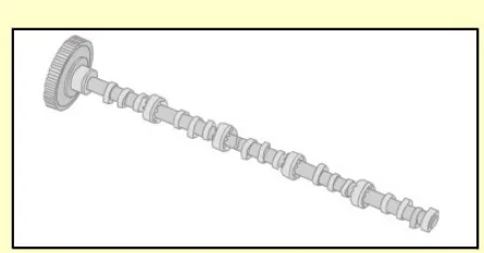
- The camshaft consists of a number of sections assembled by flange couplings, joined with fitted bolts and nuts.
- For each cylinder it carries one cam for the fuel pump, one cam for the exhaust valve, and one cam for the inlet valve.
- Cams are accurately positioned on the shaft by shrunk fit. The flange couplings, the fuel pump cams and the exhaust valve cams are shrunk onto the shaft by heating.
- Dismantling of the flanges is effected hydraulically, by injecting lubricating oil between the shaft and the flange.
- Camshafts are heat treated and the cams are surface hardened to take impacts.
- The camshaft is carried by a series of camshaft bearings, which are thin shell type, made of trimetal with a steel back, and fitted in the frame.
- Along the camshaft the frame has large openings for inspection of the fuel pump rollers, cams and bearings.
Adjustment of engine timing is carried out by forcing lubricating oil in between the cam and the shaft, which enables the parts to be turned in relation to each other. This is the same hydraulic principle used to dismantle the flanges, and it is how a cam is advanced or retarded on the shaft without removing it.
The gear drive
- The crankshaft drives the camshaft through the gear drive.
- The gear wheel drive for the camshaft is located at the flywheel end of the engine, enclosed by a two-piece end shield or cover.
- The gear drive is driven by the crankshaft and transmits rotational motion to the camshaft, at the same speed as the engine, or at half the speed of the crankshaft.
On a four-stroke engine it is at half speed, and the tooth counts enforce it. Four-stroke engines have twice as many teeth on the camshaft gear as on the crankshaft gear. This means the camshaft runs at half the speed of the crankshaft, and the camshaft turns — operating the injection and the valves — only once for every two revolutions of the crankshaft.
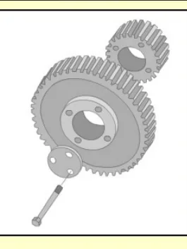
The gears or sprockets are fitted to the crankshaft and camshaft by keys, so they can only be fitted in one position. However, they can be incorrectly lined up to each other. This is why the timing marks exist, and why they must be checked whenever the gear train has been disturbed.
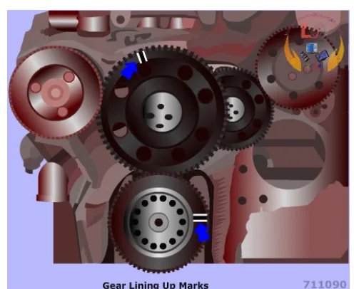
A small timing error will cause loss of power and overheating. A large error and the engine will not start.
4. The fuel injection pump
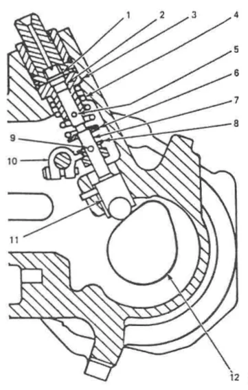
Each cylinder is provided with a fuel pump. It supplies pressurised fuel oil to the fuel injector. Fuel pump cams, mounted on the camshaft, operate the fuel pumps, and the cams are arranged so that fuel is injected according to the firing order.
The fuel racks of the pumps regulate the quantity of fuel delivered to the injector. The fuel racks of all the pumps are connected to the governor through linkages. That linkage is how the governor controls the engine's speed: it moves all the racks together, and the racks decide how much fuel each cylinder gets.
The Bosch type pump
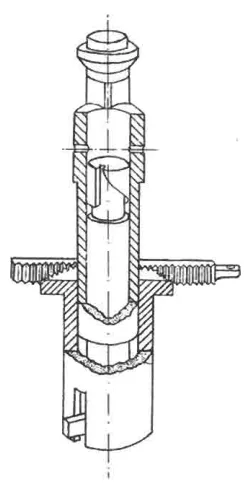
The most common fuel pump used on auxiliary diesel engines is the Bosch type. It is a cam operated jerk pump with a helical groove on the plunger to control the fuel cut-off, and therefore the quantity of fuel delivered to the cylinder.
How the helix meters the fuel:
- With the plunger at the lower limit of its travel, fuel enters the barrel through the inlet port.
- As the cam lifts the plunger, it closes the inlet port with its top edge, trapping fuel above the plunger.
- Further lift pressurises the trapped fuel, which lifts the spring-loaded delivery valve and goes to the injector.
- The injection ends when the helical groove on the plunger uncovers the spill port. The trapped fuel escapes back to the suction side, the pressure collapses, and the delivery valve shuts.
- Rotating the plunger changes where along its travel the helix uncovers the port, and therefore changes how much fuel is delivered. The plunger is rotated by a quadrant collar on a sleeve, moved by the fuel rack.
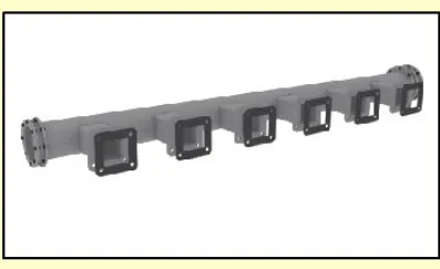
Arrangement: these pumps can be arranged singly along the camshaft, one at each cylinder position, or they may be housed in a single block. Each pump unit contains a pump plunger and guide, together with a spring-loaded delivery valve and its seat.
One important handling rule: plungers and guides are not interchangeable. They should be treated as combined units or elements. Each plunger is lapped to its own guide to a fit of a fraction of a micron, and swapping them destroys the fit.
The sleeve-metered pump
A second metering method is used on some engines. In a sleeve-metered fuel injection pump, the quantity of fuel is set by the position of a sleeve rather than by a helix on the plunger.
The principle is the same — the injection ends when a port is uncovered and the pressure collapses — but the port is uncovered by moving the sleeve up and down, instead of by rotating a helically grooved plunger. The advantage is that the plunger does not have to rotate, which removes the quadrant and the rack-to-plunger linkage from the metering path.
5. The fuel injector
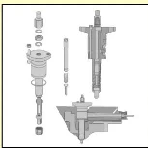
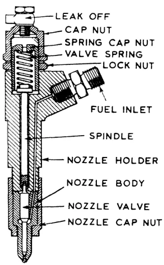
The fuel injector — also called the fuel valve — is fitted on the cylinder head, which encompasses the combustion chamber. It is mounted on the head by an integral flange in the holder and two studs with distance pieces and nuts.
Construction:
- A valve body, or nozzle holder, to which the nozzle is secured by a retaining nut.
- Inside the body, a spring and its compression nut, and an intermediate spindle where one is necessary.
- The mating surfaces between the valve body and the nozzle are ground and lapped to form an oil pressure-tight seal.
- The nozzle and needle are lapped together as a pair and cannot be replaced individually.
- The nozzle holder includes a threaded pipe stub for mounting the high-pressure pipe.
- On the uppermost part of the nozzle holder there are three sealing rings. Between the two lowest O rings, the leak-off oil from the fuel valve is led out into the space between the high-pressure piping and the protection tubing. That leak-off is a useful indicator — a sudden increase in leak-off means the nozzle needle is worn or the valve is not seating.
How it works:
The fuel valve operates hydraulically, lifting a spring-loaded valve and allowing the pressurised fuel to spray out through one or more orifices into the combustion chamber. The spring holds the needle shut until the pump's pressure is enough to lift it; the pressure at which it lifts is set by the compression nut.
The functions of the injector are:
- To open and close the passage of fuel to the combustion chamber.
- To convert the high-pressure oil from the pump into a fine spray of the desired pattern.
The spray pattern matters as much as the quantity. A poor pattern — a dribbling or off-centre nozzle — puts fuel on the liner wall instead of into the air, which causes liner wear, carbon build-up and incomplete combustion.
Cooling: the nozzle assembly and the fuel valve are cooled by the injected fuel itself. The fuel passing through on its way to the cylinder is what keeps the nozzle below the temperature at which the fuel would carbonise in the orifice. This is why a hot engine should not be stopped abruptly with a hot nozzle, and why some installations fit separate nozzle cooling water.
What happens when the pump stops delivering
When fuel pump delivery ceases, there should be a sharp drop in pressure. That sharp drop is what makes the nozzle valve close smartly, with an instant cut-off of the spray. If the pressure falls away slowly instead — because of a worn delivery valve, a leaking high-pressure pipe, or a sticking nozzle — the injection ends raggedly. The result is dribble: fuel entering the cylinder after injection should have finished, which burns late, raises exhaust temperature and cokes the nozzle.