
Crankshaft, Connecting Rod and Crosshead in Compressors
Gas forces push and inertia forces pull, so the frame must survive both and the balance decides the vibration.
Key Principles at a Glance 7 points
- Crank geometry sets the motion, because stroke is twice the crank radius and rod angularity produces the side thrust the crosshead must absorb.
- Gas forces act along the cylinder axis and are greatest near the start of compression, while inertia forces reverse with speed and rise with the square of it.
- The piston rod is a slender column under compression, so buckling rather than tensile strength governs its design.
- Unbalanced reciprocating masses generate a primary force at running speed and a secondary force at twice running speed, which is why balance and foundation design matter.
- Cylinder arrangement is used deliberately to cancel forces, and opposed and multi-throw arrangements exist to reduce what the foundation must absorb.
- Foundation bolts, shims and alignment belong in the maintenance routine, because a compressor that has moved on its foundation shows it as vibration and rod wear.
- Inspection is measurement-led, so crank deflection, bearing clearance, crosshead shoe clearance and rod runout are recorded against limits rather than judged by feel.
Learning objectives
By the end of this chapter you should be able to:
- explain how the crank mechanism converts rotary motion into piston motion;
- identify the loads carried by the crankshaft, connecting rod, crosshead, and piston rod;
- distinguish gas loads, rotating inertia loads, reciprocating inertia loads, and couples;
- explain primary and secondary forces and their frequencies;
- describe how crank arrangement and counterweights affect balance;
- understand piston-rod column loading and rod-load limits;
- identify the effects of misalignment, incorrect clearances, and poor lubrication; and
- connect vibration and knocking symptoms with likely running-gear faults.
1. Mechanical motion through the compressor
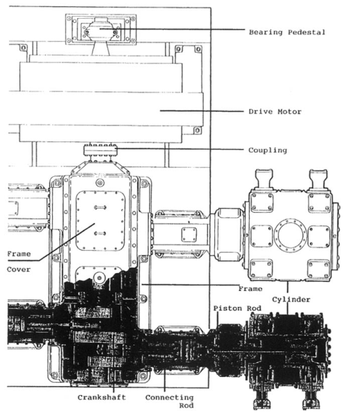
A reciprocating compressor receives rotary motion from an electric motor, engine, turbine, or other driver. The crankshaft carries eccentric crank throws. A connecting rod links each crankpin to a crosshead. The crosshead moves along a straight guide and drives the piston rod and piston.
One crank revolution produces one piston cycle. With a simple crank-slider mechanism, the piston position is not a perfect sine wave because the connecting rod has finite length. The angularity of the connecting rod produces a secondary component of piston acceleration.
The running gear must transmit gas pressure forces in both compression and tension, accelerate and decelerate the moving masses, maintain alignment, and survive millions of load cycles. Correct operation therefore depends on the entire mechanical chain rather than on the piston alone.
2. Crankshaft geometry
2.1 Crank radius and stroke
The crank radius r is the distance from the crankshaft centreline to the crankpin centreline. The piston stroke is approximately:
A longer stroke can increase displacement for a given bore, but it also increases piston speed, rod motion, inertia loading, and package size. Speed, bore, stroke, and cylinder arrangement must be selected together.
2.2 Crankshaft parts
A compressor crankshaft contains:
- main journals supported by main bearings;
- crankpins supporting connecting rods;
- webs connecting journals and crankpins;
- counterweights;
- coupling or flywheel attachment;
- oil passages where pressure lubrication is used; and
- locating or thrust features.
The shaft must resist alternating bending, torsion, bearing reactions, and local stress concentrations. Fillets at journals and crankpins are carefully designed because sharp changes in section raise fatigue stress.
2.3 Crank throws and phasing
The angular position of each throw determines the phase of each cylinder. Phasing is selected to balance forces, distribute torque, maintain acceptable interstage timing, and control discharge pulsation.
A multistage compressor may use separate cylinders with different bore sizes. The low-pressure cylinder handles the larger inlet volume; the high-pressure cylinder handles a smaller volume at greater pressure. The crank arrangement must accommodate their different gas and inertia loads.
2.4 Counterweights
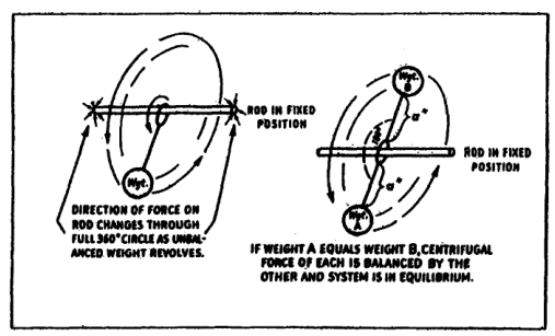
Counterweights are placed to oppose centrifugal forces from rotating masses and to reduce selected components of reciprocating inertia. A rotating mass can be balanced completely with an appropriate counterweight. A reciprocating mass cannot generally be completely balanced by a single rotating mass because its motion is linear and periodic.
Counterweight changes are not an operating adjustment. Removing, replacing, or relocating a counterweight changes shaft balance and can create dangerous vibration and bearing load.
3. Connecting rod
The connecting rod transmits force between crankpin and crosshead pin. It is loaded alternately in compression and tension, depending on gas pressure, piston direction, and inertia.
3.1 Construction
A typical rod has:
- a crankpin end with a split bearing;
- a forged or machined shank;
- a crosshead-end bearing or bushing connection;
- connecting-rod bolts or cap; and
- oil passages or drilled lubrication paths where required.
The crankpin bearing carries a rapidly changing load. Correct bearing fit, oil supply, bolt torque, and alignment are essential.
3.2 Connecting-rod loading
The rod force is the combination of:
- gas pressure force on the piston;
- inertia force of piston, rod, crosshead, and related reciprocating mass;
- friction forces at rings, packing, and crosshead shoes; and
- side reactions caused by connecting-rod angularity.
The rod does not see a constant load. Its maximum compression and tension values occur at different crank positions and operating conditions.
3.3 Rod-bearing symptoms
Possible connecting-rod or crankpin-bearing defects produce:
- frame knocking;
- metallic debris in oil;
- low oil pressure;
- bearing temperature rise;
- altered crankshaft position;
- increased vibration; and
- progressive damage to the crankpin or shaft.
A knock that changes with load or oil temperature should be investigated with pressure, temperature, and clearance measurements rather than judged by sound alone.
4. Crosshead and guide
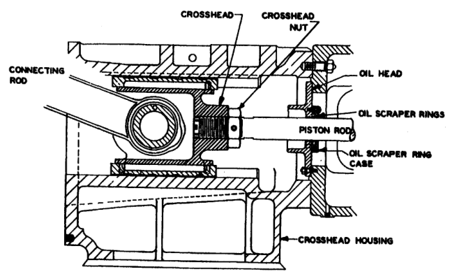
The crosshead changes the angular movement of the connecting rod into straight-line movement of the piston rod. It runs in a guide fixed to the frame and carries replaceable shoes or machined bearing surfaces.
4.1 Crosshead components
A crosshead assembly may include:
- crosshead body;
- crosshead pin;
- connecting-rod bushing;
- upper and lower shoes;
- shoe retainers;
- guide surfaces;
- piston-rod threaded connection;
- lock nut and locking device; and
- oil passages.
The crosshead pin may be fixed or allowed to float laterally or rotate according to design. Retaining rings, caps, or other features control lateral movement.
4.2 Crosshead guidance
The guide must maintain piston-rod alignment while supporting side thrust generated by connecting-rod angularity. Excessive guide clearance allows the crosshead to move, causing:
- piston-rod runout;
- packing leakage;
- piston-ring and rider-ring wear;
- cylinder scoring;
- crosshead knocking; and
- uneven shoe loading.
Insufficient clearance prevents the oil film from forming and may cause overheating or seizure. Clearances must be measured against the manufacturer’s limits; generic values are unsafe.
4.3 Crosshead lubrication
In a pressure-lubricated frame, oil may travel through the crankshaft and connecting rod to the crosshead pin bushing and shoes. Oil quality and flow must be sufficient at cold start as well as normal operating temperature.
Check:
- oil passages;
- crosshead supply holes;
- shoe contact pattern;
- guide scoring;
- shoe thickness;
- pin and bushing clearance; and
- evidence of oil starvation.
4.4 Piston-rod connection
The piston rod may be screwed into the crosshead and locked with a nut, or joined using a floating or pre-stressed coupling. Locking devices can include castellated nuts, dowels, set screws, multi-bolt locks, or hydraulic pre-stressing arrangements.
The connection must remain tight under alternating tension and compression. Incorrect locking or torque can allow the rod to turn, change piston end clearance, loosen the piston, or damage the crosshead.
5. Piston rod and rod column loading
The piston rod carries the force from the crosshead into the piston. In a horizontal or vertical cylinder it may be loaded in tension, compression, or both during a revolution.
5.1 Compression and tension
When gas pressure and inertia act so that the piston pushes against the rod, the rod is in compression. A long slender rod can deflect or buckle under compression. When the force reverses, the rod is in tension and stretches elastically.
The rod must be designed for the combined effects of:
- gas pressure difference;
- inertia force;
- rod length and diameter;
- piston mass;
- temperature;
- crosshead alignment; and
- cylinder pressure pulsation.
5.2 Frame or rod load
Frame load is the load that the compressor frame and running gear can safely carry in tension and compression. It includes the connecting rod, bolts, crosshead pin, piston rod, bearings, crankshaft, and related structure.
A useful preliminary pressure-force relationship is:
For an approximate differential cylinder load:
where A_net accounts for piston-rod area where applicable. Exact compression and tension calculations must include the pressure acting on each piston face and the instantaneous inertia force.
The weakest loaded component may govern the allowable frame or rod load. A rod can appear strong while the crosshead pin bushing, connecting-rod bearing, bolts, or frame is overloaded.
5.3 Conditions that increase rod load
Rod or frame load can increase because of:
- discharge pressure above design;
- suction pressure below design;
- excessive pressure ratio;
- liquid in the cylinder;
- overspeed;
- altered gas composition or density;
- incorrect relief-valve setting;
- blocked discharge piping;
- wrong cylinder clearance; and
- abnormal valve operation.
Operating outside the specified pressure envelope can damage parts even when the motor current appears normal.
6. Gas forces and inertia forces
The running gear is acted on by two broad categories of force:
- Gas forces, caused by pressure acting on piston areas.
- Inertia forces, caused by accelerating and decelerating piston, piston-rod, crosshead, and connecting-rod masses.
Friction and bearing reactions add further loads. The resultant changes continuously with crank angle.
6.1 Gas force
For a piston face:
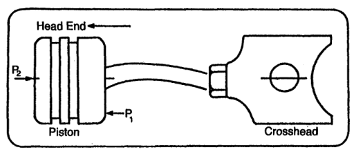
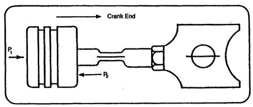
For a double-acting piston, the net force depends on the pressure on the head end, crank end, and piston-rod area. Suction and discharge pressure vary during valve opening, closing, compression, and expansion; therefore the instantaneous force is not simply the difference between receiver and atmospheric pressure.
6.2 Rotating-mass inertia
Rotating masses create centrifugal force. In simplified form:
where m is rotating mass, r is radius, and ω is angular velocity.
The force increases with the square of speed. A small speed increase can therefore produce a substantial increase in bearing and foundation loading.
6.3 Reciprocating-mass inertia
The piston, piston rod, crosshead, and the reciprocating portion of the connecting rod accelerate and decelerate. Their inertia force has primary and secondary components.
A simplified acceleration expression is commonly represented as:
where:
- r is crank radius;
- l is connecting-rod length; and
- θ is crank angle.
The first term varies once per revolution. The second varies twice per revolution.
6.4 Primary force
Primary force occurs at shaft speed. It contains contributions from rotating and reciprocating masses. Counterweights and suitable crank arrangements can reduce it significantly.
6.5 Secondary force
Secondary force occurs at twice shaft speed and results from connecting-rod angularity and reciprocating mass. It cannot generally be eliminated by ordinary counterweights. Cylinder arrangement and foundation design are therefore important.
The two significant vibration periods are:
- primary: one cycle per shaft revolution;
- secondary: two cycles per shaft revolution.
Vibration frequency can help distinguish a rotating imbalance from a reciprocating or twice-speed problem, but diagnosis should include phase, amplitude, load, and operating condition.
7. Forces and couples
A force acts through a line. A couple is produced when equal or related forces act in different planes or have an offset moment arm. A compressor may have acceptable net force but still transmit a significant couple to its foundation.
7.1 Primary and secondary couples
In a multicylinder machine, inertia forces from individual cranks may not act in the same plane. Their offset creates a moment attempting to rotate the machine about the shaft axis. This produces primary and secondary couples.
Couples depend on:
- crank spacing;
- cylinder arrangement;
- crank phase angle;
- piston mass;
- connecting-rod length;
- cylinder centre distance; and
- counterweight placement.
7.2 Balanced-opposed arrangement
In a balanced-opposed compressor, cylinders are arranged on opposite sides of the frame. With correct phasing, piston forces can cancel substantially. Closely spaced cranks reduce the moment arm and therefore reduce primary and secondary couples.
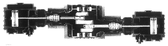
The arrangement may still transmit residual forces and pulsation. “Balanced” does not mean vibration-free; it means that selected forces and couples are reduced by geometry and phasing.
7.3 V and Y arrangements
A V or Y compressor changes the direction of forces through the cylinder angle. Some force components can be transferred or combined in a way that reduces foundation loading, but secondary forces may remain. A single-cylinder or Y-type machine can require foundation design to absorb unbalanced components that cannot be cancelled by the crank arrangement.
7.4 Force-balance table
The source gives relative force and couple values for several arrangements. The exact values depend on the machine, but the design lesson is general:
- counterweights can eliminate or reduce selected primary components;
- secondary force is more difficult to balance;
- opposed cylinders can cancel force through equal and opposite motion;
- close crank spacing reduces couple moment; and
- foundation design remains necessary even on a balanced machine.
8. Foundation and alignment connection
The foundation receives the remaining static, gas, inertia, and couple loads. It must be sufficiently massive and stiff to prevent sliding, rocking, tilting, or loss of alignment.
Poor foundation conditions can cause:
- frame distortion;
- crankshaft misalignment;
- bearing edge loading;
- crosshead shoe wear;
- piston-rod runout;
- packing failure;
- piston and cylinder scoring; and
- pipe stress.
The foundation and compressor must be treated as a dynamic system. A strong compressor on a weak or uneven foundation is not a reliable installation.
8.1 Alignment path
The alignment path is:
A defect anywhere in this chain can appear at another location. For example, a foundation shift can present as a packing leak; a bent piston rod can present as rider-ring wear; a worn crosshead shoe can present as cylinder scoring.
8.2 Piping forces
Suction, discharge, and interstage piping must not impose excessive external forces or moments on the cylinder. Thermal expansion, unsupported coolers, rigid connections, and pulsation bottles can distort the machine.
Piping support must be checked during installation and after maintenance because a moved support or altered gasket stack can change alignment.
9. Mechanical balance and operating speed
Speed influences nearly every mechanical load:
- piston speed increases approximately with speed;
- inertia force increases approximately with speed squared;
- valve impact frequency increases with speed;
- bearing heat generation increases with speed and load; and
- vibration may approach a structural or foundation natural frequency.
A compressor must not be oversped to obtain extra capacity without confirming rod load, valve dynamics, lubrication, cooling, and vibration limits. Capacity improvement through speed may be much more expensive mechanically than the apparent increase in flow suggests.
9.1 Resonance risk
If an excitation frequency approaches a natural frequency of the frame, foundation, piping, or connected structure, vibration amplitude may rise sharply. Excitation sources include:
- one-times shaft speed;
- twice shaft speed;
- cylinder firing or compression frequency;
- valve-impact frequency; and
- pressure pulsation frequency.
Avoiding resonance requires design analysis, measurement, and controlled operating speed. A vibration alarm should not be defeated simply because the compressor continues to deliver air.
10. Inspection and measurement
10.1 External running inspection
During operation, record:
- shaft speed;
- suction and discharge pressure;
- interstage pressures;
- cylinder and discharge temperatures;
- oil pressure and temperature;
- vibration at frame, bearings, and cylinder;
- packing leakage; and
- unusual noise.
Compare readings with previous records. A gradual trend can be more informative than one absolute value.
10.2 Stopped inspection
After isolation and depressurisation, inspect:
- crankcase oil and magnetic plugs;
- main-bearing and crankpin clearances;
- crosshead shoes and guides;
- crosshead pin and bushing;
- connecting-rod bolts and bearing shells;
- piston-rod connection and locking device;
- rod runout;
- piston end clearance;
- foundation bolts and grout; and
- coupling and flywheel condition.
10.3 Measurement principles
Use calibrated instruments and record temperature, measurement location, crank angle, and direction. Do not compare a cold clearance measurement with a hot running limit without understanding the manufacturer’s method.
Measurements commonly include:
- shaft runout;
- web deflection;
- rod runout;
- bearing clearance;
- crosshead clearance;
- piston end clearance;
- foundation movement; and
- vibration amplitude and phase.
10.4 Web deflection
Web deflection measurements can reveal crankshaft alignment or frame distortion. The measurement must follow the maker’s specified crank positions and procedure. A single reading is not enough to diagnose a bent shaft or a poor foundation.
11. Failure modes and causes
| Failure | Common mechanical causes |
|---|---|
| Crankshaft fatigue crack | Excessive bending, poor fillet condition, misalignment, overload, torsional vibration |
| Main-bearing wipe | Low oil pressure, dirty oil, excess clearance, overload, shaft misalignment |
| Crankpin bearing damage | Incorrect clearance, oil starvation, rod load, bolt or cap movement |
| Crosshead shoe wear | Poor lubrication, excessive clearance, guide distortion, dirt, side load |
| Piston-rod breakage | Excessive rod load, fatigue, bending, thread damage, incorrect pre-stress |
| Packing failure | Rod runout, poor finish, misalignment, overheating, incorrect adjustment |
| Piston or cylinder scoring | Insufficient clearance, broken ring, liquid entry, dirt, misalignment |
| Foundation cracking or movement | Excessive dynamic load, inadequate mass, poor soil, poor grout, resonance |
| Persistent frame vibration | Unbalance, couple, loose fasteners, piping forces, pulsation, resonance |
The correct repair addresses the load path. Replacing a bearing without correcting oil supply or alignment allows the failure to return.
12. Worked reasoning example
Problem
A two-stage compressor develops a new frame knock after a maintenance overhaul. Oil pressure is slightly lower than normal, vibration is highest near the crankcase, and the knock increases with speed.
Reasoning
- A speed-related knock suggests a running-gear or rotating component rather than a purely gas-end valve fault.
- Slightly low oil pressure raises suspicion of internal leakage, a dirty strainer, or bearing clearance.
- The maintenance history makes incorrect bearing assembly, loose connecting-rod bolts, incorrect crosshead clearance, or a loose counterweight possible.
- Stop the compressor and inspect oil for metal.
- Verify pump operation, filter condition, and relief-valve setting.
- Measure main-bearing, crankpin, and crosshead clearances.
- Check counterweight fasteners and crankshaft runout.
- Check foundation and coupling fasteners.
- Do not continue operating solely because pressure and capacity remain normal.
The machine may continue to deliver air while a bearing or fastener progresses toward catastrophic failure.
13. Revision questions
- How does a crankshaft produce reciprocating motion?
- What is the relation between crank radius and piston stroke?
- List the main parts of a compressor crankshaft.
- Why are crank fillets important?
- What determines crank-throw phasing?
- What forces act on a connecting rod?
- What is the function of a crosshead?
- Why must crosshead-guide clearance be controlled?
- What can cause piston-rod runout?
- Define frame or rod load.
- Why can the weakest running-gear component govern the allowable rod load?
- Distinguish gas force from inertia force.
- What is rotating-mass centrifugal force?
- What is a primary inertia force?
- What is a secondary inertia force?
- Why do couples occur in multicylinder compressors?
- How does an opposed-cylinder arrangement reduce vibration?
- Why can a balanced compressor still require a substantial foundation?
- How does speed affect inertia force?
- What measurements help diagnose running-gear problems?
- What conditions can produce a frame knock?
- Why may a packing leak be caused by a foundation problem?
- Why should counterweights never be altered casually?
- What is the purpose of web-deflection measurement?
- Give a safe investigation sequence for a new crankcase vibration.
14. Self-test scenarios
Scenario A — vibration at twice shaft speed
A compressor shows a strong vibration component at twice shaft speed. Suspect secondary reciprocating forces, crank arrangement, crosshead or piston mass changes, looseness, or resonance. Check phase and compare with previous vibration data before assuming the crankshaft is unbalanced.
Scenario B — repeated piston-rod packing failures
Check rod runout, crosshead clearance, guide wear, foundation movement, cylinder alignment, rod surface, and packing cooling. Replacing packing alone does not correct a rod that is moving laterally through the gland.
Scenario C — high rod load after process change
A change in gas composition, suction pressure, or discharge pressure may increase gas force or alter inertia balance. Recalculate compression and tension loads for the new case and verify relief settings, valve operation, and cylinder clearance.
Scenario D — crankpin bearing damage with clean oil
Clean oil does not exclude overload, incorrect bearing clearance, shaft alignment error, cap movement, or incorrect bolt torque. Inspect the complete load path and verify crankshaft geometry.
15. Summary
The crankshaft, connecting rod, crosshead, and piston rod form the mechanical load path between driver and gas end. Their geometry determines motion, force, balance, alignment, vibration, and service life.
Gas forces vary with cylinder pressure. Rotating masses create centrifugal forces. Reciprocating masses create primary and secondary inertia forces. Multicylinder arrangements create couples when forces act in separate planes. Counterweights and balanced-opposed layouts reduce selected components but cannot eliminate every dynamic load.
Correct rod load, bearing clearance, crosshead guidance, piston-rod alignment, foundation stiffness, piping flexibility, lubrication, and operating speed are all required for reliable service. A compressor should be diagnosed as a dynamic system: vibration, oil pressure, temperature, pressure ratio, capacity, and mechanical measurements must be interpreted together.