
The Diesel Generator Set — Bedding Down, Coupling and Driving the Alternator
How the engine and the alternator are joined into one machine, how that machine is bedded down to the ship, and what the alternatives to a diesel generating set look like.
Key Principles at a Glance 5 points
- The auxiliary engine's speed is not its own: because it drives an alternator, its speed is fixed by the frequency required, nominally 50 or 60 Hz.
- It is a constant speed machine, and that is why it has a hydraulic governor with droop rather than the variable-speed governor of a propulsion engine.
- The auxiliary engine must be able to take load quickly, because it may be the standby machine that comes on when another set trips or when the load rises.
- It must be kept warm, its lubricating oil must be primed, and it must be capable of accepting a large block of load in a few seconds.
- When diesel generators are arranged for automatic operation it is good policy to circulate the off-duty sets with main engine cooling water so that they stay in a state of readiness, which limits pre-starting preparations to lubricating oil priming.
1. What a generating set is made of
The maker's alignment figures, chocking and holding-down bolt data, and mount deflections override these notes. A generating set is not run with a mount known to be contaminated, collapsed or loose.
A diesel generating set is a diesel engine, a flywheel, a coupling and an alternator, all mounted on a common bedplate. The bedplate in turn sits on the tank top or on stools, held by holding-down bolts through chocks.
The order of parts along the shaft line is fixed by the engine's construction:
- The crankshaft carries a solid half coupling forged integrally with it.
- That half coupling carries the flywheel.
- The generator's own half coupling mates to the flywheel.
- The main coupling bolts pass through all three — the crankshaft half coupling, the flywheel, and the generator half coupling.
There is one detail worth remembering because it decides what you can and cannot do when the alternator is off. Two additional bolts are incorporated to retain the flywheel on the crankshaft when the generator is uncoupled. Without those two bolts, taking the alternator off would leave the flywheel sitting on the end of the crankshaft held by nothing. If the set is ever run, or barred over, with the alternator removed, those two bolts are what keep the flywheel in place.
Axial location of the crankshaft is maintained by renewable thrust rings. These take the magnetic pull of the alternator and any axial thrust from the drive, and they are a wear item.
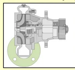
What the flywheel does
The flywheel is attached to the crankshaft and has two jobs.
It stores energy. During the power stroke the engine produces more energy than the load needs; the flywheel absorbs the excess. During the suction, compression and exhaust strokes it gives that energy back. It acts as a power reservoir, smoothing the torque delivered to the alternator — which matters far more for a generator than for a propeller, because the alternator's output frequency follows the shaft speed directly.
It carries the timing marks. Markings are made on the flywheel circumference with reference to top dead centre and to the timing of fuel injection. These marks are how the engine is timed and how valve and injection settings are checked.
Machinery driven from the free end
Auxiliary machinery may be driven from the free end of the crankshaft, through a clutch — an air compressor or a bilge pump, for example. Where this is fitted, it is a load on the engine in its own right, and it must be accounted for when the set's capacity is considered.
2. Bedding the set down to the ship
Chocks and holding-down bolts
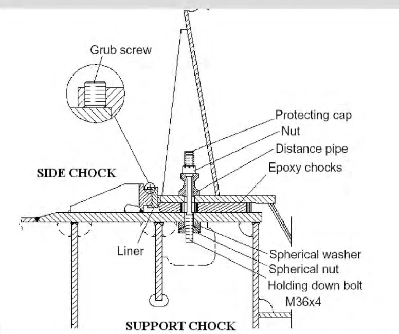
The set is held down by holding-down bolts passing through chocks — the packing pieces that carry the engine's weight and transmit its forces into the ship's structure.
The chock may be cast in place from epoxy resin, and the resin chock has to satisfy conditions on both its static and its working pressure. Typical figures from a medium-speed installation:
- Static pressure on the chock — the engine weight divided by the chock area — must stay below the resin's allowable figure. In a worked example, a pressure of 0.66 N/mm² against a limit of 0.69 N/mm².
- Total static pressure, which includes the tension in the holding-down bolts as well as the weight, must also stay within limits — 3.167 N/mm² against 3.43 N/mm² in the same example.
- The total force in the holding-down bolts must exceed 2.5 times the engine weight. With 64 bolts each at 570,428 N the total is 36,507,392 N against a required 24,328,018 N, so the condition is met.
That third condition is the one that matters in service. The bolts must be tight enough that the chock never goes into tension — the engine must never be able to lift off its seat.
Resilient mounting
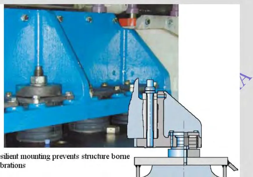
For medium-speed engines, mounting the engine on resilient chocks is often a better option than rigid chocking. A resilient mounting will damp the vibration transmitted from the engine into the tank top very substantially — 10 to 20 % of the original level, according to one maker's figure.
The reason it is wanted is resonance. The natural frequencies of the ship's structure cannot easily be changed — the hull sits at 2–5 Hz, the stern at 4–7 Hz, and the decks and bulkheads at 10–15 Hz — because changing them costs money. So instead of moving the structure out of the way of the engine's frequencies, the engine's frequencies are reduced until they no longer excite it.
Why resilient mounting suits four-stroke engines specifically:
- A two-stroke's high rotational and static masses produce larger out-of-balance forces, and preclude resilient mounts, which must also carry the engine's weight. For scale: a 12-cylinder 10,860 kW four-stroke weighs about 155 tonnes, while a 9,600 kW five-cylinder two-stroke weighs about 305 tonnes.
- Four-strokes are lighter, have lower out-of-balance forces, and are smaller, so a more rigid engine seating is easier to produce.
- Most of the hull's natural frequencies are away from the four-stroke's operating range. An engine running at 400–1500 rpm transmits frequencies of roughly 6.7–25 Hz depending on cylinder number, and its ignition frequencies run from 27–450 Hz. A two-stroke's ignition frequencies run only 4.7–25 Hz — straight into the hull and stern frequencies.
The last point is the decisive one. The four-stroke's frequencies sit in ranges the hull does not occupy, so there are fewer ranges and lower amplitudes to subdue.
How the mounts are fitted and looked after:
- The number and location of the flexible mounts is given by the engine manufacturer. Conical mounts are usually used; being vertical they are easier to install than inclined mounts.
- The engine is aligned to the gearbox or the generator before the mounts are installed, taking account of the misaligning factors.
- The load or compression of each mount should be similar, with a tolerance of about 2 mm on conical mounts.
- The mounts are made from natural rubber, chosen for its vibration-damping properties. Contamination with oil, or even oily water, must be avoided. Covers must always be in place and regular checks made that contamination is not occurring.
- The rubber elements are designed to take both compression and shear, and the mounts have built-in buffers to limit excessive movement in heavy weather and during starting and stopping. Side and end buffers may also be fitted.
The engine moves, and everything attached to it must allow for that. Typical figures are that the crankshaft centre moves about ±1 mm and the top of the engine about ±5 mm during starting, with further movement of similar size from torque reaction at full load. Creep and thermal expansion add to it. So:
- All pipework connections to the engine must be flexible, and so must access ladders and cabling. Flexible connections must be adequately secured at both ends, and the engine must not be allowed to impose high tensile stresses on them — otherwise premature failure will result.
- All the rigidity for crank alignment must come from the single cast engine block. A flexible mounting means the engine seating cannot contribute any stiffness. This is why only underslung crankshaft engines are chosen for resilient mounting — the crankshaft must be carried by the block itself.
3. Driving the alternator from the main engine
A diesel generating set is not the only way to make electricity, and on many ships the auxiliary engines are shut down at sea in favour of a generator driven from the main propulsion system. It is worth knowing these arrangements, because the engineer is often asked why the auxiliary engines are running when they need not be — and because a shaft generator installation changes what the auxiliary engines are for.
Generators can be driven from the propeller shaft, through a gearbox, or by being mounted on the engine itself. Assuming the main engine runs on residual fuel, all the electrical power at sea is then provided at much lower cost, in fuel price and in auxiliary engine running hours. The diesel driven generator is needed only while manoeuvring and in port.
Direct current generators — the simple case
Direct current generators are not as sensitive to speed variation as alternating current machines, because frequency has to be maintained on an a.c. system and not on a d.c. one. A d.c. generator with an automatic voltage regulator can hold its output voltage even with a 10 or 15 % speed reduction. Belt-driven or shaft-mounted d.c. generators with AVRs were therefore fitted to save space and reduce workload, and could continue in operation through a moderate speed reduction, with auxiliary diesels brought in only for manoeuvring.
Alternators from a variable-speed engine — the problem
Once alternating current replaced direct current, the shaft generator had a frequency problem: an alternator's frequency is locked to its speed, and the main engine's speed varies. There are four answers:
- A d.c. shaft generator feeding a d.c. motor, which drives the alternator at constant speed. This permits moderate main engine speed reduction before a changeover to auxiliary generators is necessary.
- A controllable pitch propeller with a constant-speed engine, rather than an engine which has to be directly reversed.
- Electronic circuits developed to maintain level frequency through main engine speed changes.
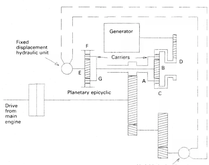
- A mechanical constant speed drive, using an epicyclic gear train.
The mechanical constant speed drive
The arrangement uses speed increasing gears to take a drive from the main engine system and split it two ways. One gear train drives a variable delivery hydraulic pump. The other drives the planet carrier of an epicyclic gear train. Rotation of the planet carrier with the central sunwheel fixed causes the annulus to drive the output. By varying the hydraulic pump's delivery, the sunwheel speed is varied, and the output speed is held constant while the input speed changes.
Power take-off arrangements
Where the generator is driven from the main engine through gearing rather than directly, the arrangement is described by where the gear is placed:
| Designation | Arrangement |
|---|---|
| BW I | Gear with a vertical generator mounted onto the fore end of the diesel engine, with no connection to the ship structure |
| BW II | A free-standing gear mounted on the tank top, connected to the fore end of the engine, with a vertical or horizontal generator |
| BW III | A crankshaft gear mounted onto the fore end of the engine, with a side-mounted generator, again with no connection to the ship structure |
| BW IV | A free-standing step-up gear connected to the intermediate shaft, with a horizontal generator |
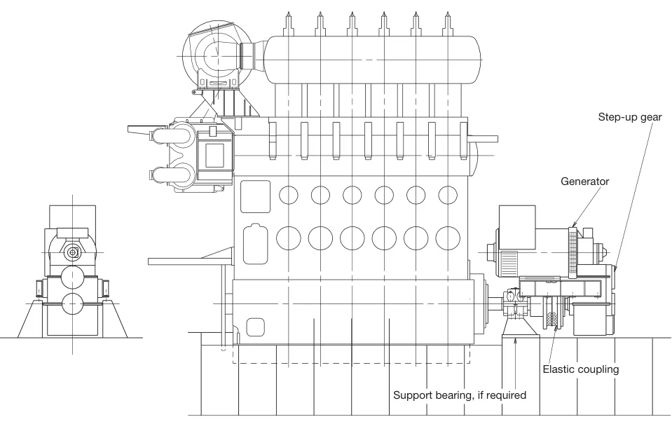
The direct mounted generator and the shaft mounted generator are special cases in which the generator is coupled directly to the main engine crankshaft, or to the intermediate shaft, without a gear. Frequency is then controlled electrically rather than by gearing.
Power turbines
Power turbines, driven by the exhaust gases in the same way as a turbocharger, convert waste heat into mechanical energy. That energy is delivered to the main propulsion system through a fluid coupling, or used to provide an integrated drive with a diesel for a generator. On a very large slow-speed engine the waste heat available is sufficient for the whole electrical load at sea, and the fuel saving is around 10 %, with additional savings in maintenance.
The trend towards longer stroke, slower running engines with constant pressure turbocharging has reduced the waste heat available, which is why modern installations chase the remaining energy harder rather than assuming it will always be there.
4. What follows for the auxiliary engine
Two practical consequences run through the rest of these chapters.
The auxiliary engine's speed is not its own. Because it drives an alternator, its speed is fixed by the frequency required — nominally 50 or 60 Hz. It is a constant speed machine, and that is why it has a hydraulic governor with droop rather than the variable-speed governor of a propulsion engine. The governing chapter (Chapter 7) deals with this in full.
The auxiliary engine must be able to take load quickly. Because it may be the standby machine that comes on when another set trips or when the load rises, it must be kept warm, its lubricating oil must be primed, and it must be capable of accepting a large block of load in a few seconds. When diesel generators are arranged for automatic operation, it is good policy to circulate the off-duty sets with main engine cooling water so that they are in a state of readiness; pre-starting preparations are then limited to lubricating oil priming.