
The Engine Structure — Bedplate, Frame, Crankshaft and Main Bearings
The stationary parts of the auxiliary engine — the bedplate, the frame and cylinder block, the crankshaft and the main bearings.
Key Principles at a Glance 6 points
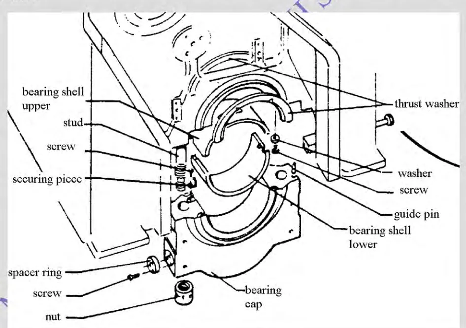
- The bearing housings are fitted in the transverse girders of the frame and secured with steel bearing caps, held by studs with hydraulically tightened nuts.
- Hydraulic tightening is used because the studs must be stretched to a precise tension, and a hammer is not a measuring instrument; the caps are additionally secured by pinching screws that stop them moving sideways under load.
- The main bearings are traditional or underslung type and of shell type — thin-wall, steel-backed, and lined with white metal or aluminium-tin.
- The load path from the combustion space to the crankshaft runs through the cylinder head studs, the block, the frame, the bearing cap and its studs, and finally into the shell.
- Clearance is checked without opening up by a bridge gauge read through the crankcase, or by the lead wire method, in which soft lead wire is squeezed to the clearance and measured with a micrometer.
- A bearing shell must be rejected for a wiped or discoloured running surface, embedded foreign particles, cracking or fatigue of the lining, or loss of bond between lining and steel back.
1. The bedplate
The maker's clearances, deflection limits and bolt tensions govern. A crankshaft deflection reading outside the maker's limit is not a matter of opinion — the engine is not run until it is investigated.
The bedplate is the foundation. It is a box-shaped single construction and constitutes the main structural member of the engine.
It does three jobs:
- It carries the main bearings and therefore the crankshaft.
- It transmits the engine's weight and its reaction forces into the ship's structure through the chocks and holding-down bolts.
- It acts as the lubricating oil reservoir. The bedplate is the sump, and a dipstick is provided to ascertain the level.
The bedplate may be welded or cast. Cast iron is common on medium-speed engines; welded fabrication is common on larger machines.
Trestle and deep box types
Two arrangements are found:
- The trestle type sits upon two parallel stools or raised portions of the ship's structure running fore-and-aft. The bedplate is a relatively light structure spanning between them.
- The deep box type is a box girder — a deep, closed section which is stiff in bending and in torsion in its own right, and which needs less help from the ship's structure beneath it.
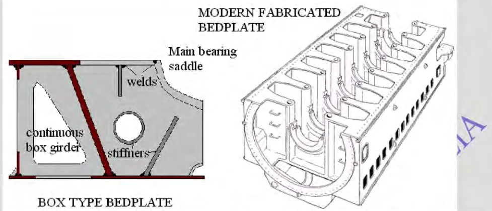
The fabricated bedplate
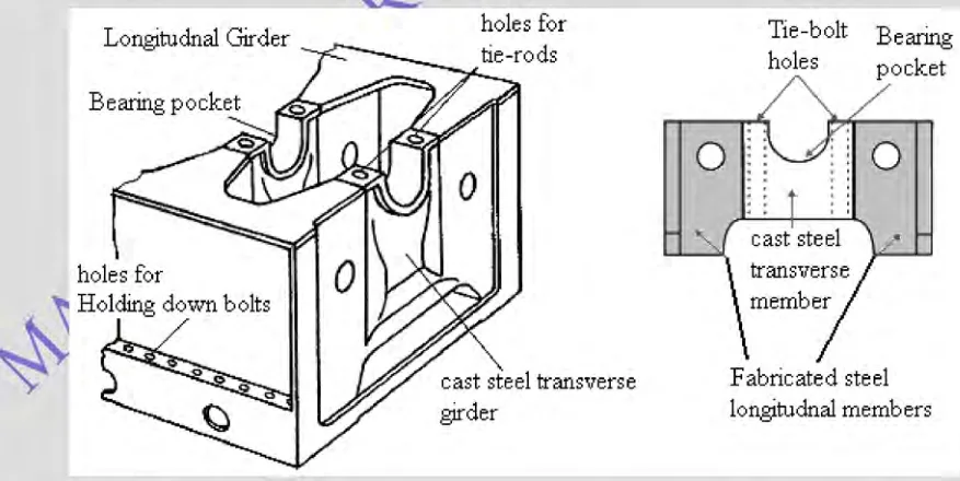
A fabricated bedplate is built up rather than cast, and its features are worth naming because they are what you see when you look into the crankcase:
- Fabricated steel longitudinal members — the two main girders running the length of the engine.
- Cast steel transverse girders, welded in between them.
- Bearing pockets machined into the transverse girders to locate the main bearing shells.
- Continuous box girder construction, with stiffeners where the loads come in.
- Holes for the holding-down bolts, through which the engine is fastened to the ship.
- Holes for the tie-rods, where the engine uses them.
- Main bearing saddles, machined to take the bearing shells directly.
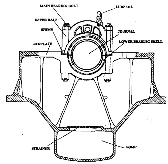
The bedplate carries the main bearings
The bedplate carries thin-wall, steel-backed, white-metal or aluminium-tin lined main bearings. On a generating engine, an additional bearing is incorporated to carry the combined loads of the flywheel and part of the weight of the generator. That bearing exists because the alternator is heavy and its rotor pulls on the end of the crankshaft; without it, the flywheel end main bearing would be carrying a load it was never sized for.
2. The frame and the cylinder block
The cylinder block, or frame, consists of a number of cylinders cast in a single piece. It is a monobloc structure, either vertical in-line type or Vee type.
The construction is straightforward:
- The liners are inserted in the bores of the cylinder block.
- Between the liner and the cylinder block, the cooling water is circulated. This is what keeps the liner cool, and it is why the liner's outer surface must be clean and the sealing rings sound.
- The complete cylinder block is located above the crankcase and is supported by it.
The engine frame is cast iron. On a medium-speed auxiliary engine the frame is typically a monobloc casting, often described as an A-frame when it is a separate piece bolted to the bedplate. The turbocharger bracket is usually part of the same casting, and houses the air cooler.
Monobloc against separate structures
This is where the medium-speed auxiliary engine differs most sharply from a slow-speed main engine.
On a large slow-speed two-stroke, the bedplate, the A-frames and the entablature (the cylinder block) are separate structures bolted together, and are held in compression by tie rods. The tie rods matter because the gas load tries to lift the cylinder head off and stretch the frame; the tie rods keep the whole column in compression so that the castings are never in tension. A single part can be lifted out and replaced.
On a medium-speed four-stroke, the frame is usually a single monobloc casting. It is stiffer and lighter for its size, but it means that the crankshaft cannot be taken out sideways — in the classic arrangement it is necessary to lift the A-frame if the crankshaft is to be removed. Some designs incorporate a C-frame arrangement, which permits side removal of the crankshaft.
3. The crankshaft
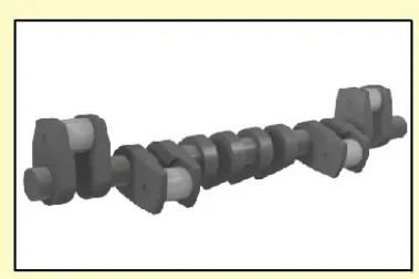
The crankshaft is the one part of the engine that converts reciprocating motion into rotation, and it is the most highly stressed part in the machine.
Construction of a medium-speed auxiliary engine crankshaft:
- One-piece alloy steel, slab-forged, oil-hardened and tempered.
- Ground main and crank pin bearing journals — the running surfaces, finished to a fine tolerance.
- A solid half coupling forged integrally with the shaft, which carries the flywheel and hence the alternator.
- Counterweights fitted by two dovetail joints and secured by a centrally placed screw, to ensure adjustable bearing pressure and balancing. Where necessary, balance weights are bolted to the crank webs.
- The gear wheel for the camshaft drive is fitted to the aft end of the crankshaft.
- A claw type coupling for the lubricating oil pump is fitted at each end — so that the same crankshaft can be used for engines of either rotation, or so that the pump can be driven from whichever end is convenient.
- Axial location is maintained by renewable thrust rings.
- Drilled passages in the crankshaft feed oil from the main bearings to the connecting rod bearings. In some engines these oil passages are arranged to provide a continuous supply of oil to the cooled pistons as well.
Balancing
A four-cylinder in-line engine with its cranks at 180° has an inherent secondary imbalance, and requires secondary balancing gear. This is not a refinement — without it the engine would shake the ship's structure at twice running speed.
Crankshaft deflection
Crankshaft deflections are measured to detect misalignment of the main bearings. Misalignment occurs from bearing wear or from deflection of the crankshaft itself, and the measurement is made by reading the change in the gap between the crank webs as the shaft is turned.
The measurement matters because the crankshaft is stiff enough to resist the misalignment rather than follow it. If the bearings are out of line, the crankshaft is bent every revolution as it rotates, and the bending stress is added to the already high working stress. A deflection reading that drifts from the previous one is the earliest warning of a bearing problem, and it is why deflections are recorded and compared, not merely checked against a limit.
What damages a crankshaft
The recognised causes of crankshaft trouble are worth listing, because most of them are maintenance failures rather than manufacturing failures:
- Misalignment due to worn-out main bearings and excessive bending.
- Vibration due to incorrect power balance, running in a critical band, or running with a misfiring unit.
- Defects during manufacture — slag inclusions, incorrect heat treatment.
- Fretting corrosion, which increases with load, amplitude of movement, and running hours.
4. Main bearings and their housings
The main bearings carry the crankshaft and take the firing load of every cylinder. Their construction and their housing are both important.
The housings:
- The bearing housings are fitted in the transverse girders of the frame and secured with bearing caps made of steel.
- The caps are provided with side guides and are held in place by studs with hydraulically tightened nuts. Hydraulic tightening is used because the studs must be stretched to a precise tension, and a hammer is not a measuring instrument.
- The caps are additionally secured by pinching screws inserted horizontally through the engine frame, which stop the cap moving sideways under load.
The bearings:
- The main bearings are traditional or underslung type, and are of shell type.
- The running surface is trimetal, coated with steel at the back. A typical medium-speed construction is a thin-wall, steel-backed shell lined with white metal or aluminium-tin.
- The bearing housing encloses the main bearing shells, within which the crankshaft rotates. The bottom housing supports the crankshaft.
- Bolts transmit the reaction forces of the cylinder heads to the crankshaft main bearings via the cylinder block. In other words, the load path from the combustion space to the crankshaft runs through the cylinder head studs, the block, the frame, the bearing cap and its studs, and finally into the shell.
- Oil is supplied to each individual main bearing through a bore in the frame, connected to the engine's external main lubricating oil pipe.
Bearing clearances and inspection
Clearance is checked in two ways — without opening up, and by inspection and overhaul. The without-opening-up methods are the ones used routinely: a bridge gauge reading taken through the crankcase, or a lead wire method, in which a piece of soft lead wire is laid across the journal and the cap is tightened over it, so that the wire is squeezed to the clearance and can then be measured with a micrometer.
A bearing shell must be rejected if it shows the recognised signs of failure — wiped or discoloured running surface, embedded foreign particles, cracking or fatigue of the lining, or loss of bond between lining and steel back.
The bottom end and the top end
The same discipline applies at the connecting rod. Bottom end bolts on medium-speed engines are subject to repeated stress and fluctuating stress, and are tightened to a specified stretch, not a torque. Top end bearings and bushes are checked for clearance and for the condition of the gudgeon pin.