
The Alternator and Switchboard — AVR, Load Shedding and the Automatic Plant
The engine has been described; this chapter describes what it turns and where the power goes.
Key Principles at a Glance 5 points
- The engine must hold speed tightly, because frequency is the engine's responsibility — a wandering governor is an electrical fault as far as the ship is concerned.
- The engine must accept load in steps without losing speed badly, because the transient dip figures apply to frequency as well as voltage, and the flywheel and governor together determine how well it copes.
- The engine must be ready to start and take load automatically, which is a requirement on the starting system, the prelubrication and the warming arrangements as much as on the engine itself.
- The engine must fail safe: if the engine trips the breaker must open and the load must transfer or shed, and if the electrical system faults the engine must be protected from the consequences.
- Everything else in the set — the emergency generator, the operating procedures, the maintenance and the safety arrangements — follows from those four requirements.
1. What the alternator does
The alternator, its excitation system and the switchboard are the maker's and the classification society's equipment. The engine-side limits — rated speed, rated load and the transient behaviour of the set — govern how the machine may be loaded. The protection settings are set by the electrical authority and are not adjusted at sea.
A generator set is an engine bolted to a machine that makes electricity. In nearly every modern installation that machine is an alternating current generator, or alternator.
The alternator is a synchronous machine. Its output frequency is locked to the speed at which it turns. There is no slipping, no belt, no clutch between the engine and the electrical output — the frequency is the speed. This single fact is the reason the engine's governor matters so much: an engine whose speed wanders produces electricity whose frequency wanders with it, and frequency is one of the two quantities the whole ship's electrical system depends on.
The relationship is fixed and simple:
frequency (Hz) = (number of pole pairs × speed in rpm) ÷ 60
For a machine running at 1,500 rpm with two pole pairs, the frequency is 50 Hz. For a machine running at 1,800 rpm with two pole pairs, it is 60 Hz. This is why a 50 Hz auxiliary engine runs at 1,500 rpm and a 60 Hz one at 1,800 rpm — the engine speed is chosen to suit the alternator, not the other way round. A four-pole machine at 1,500 rpm and a 50 Hz supply go together; change the pole count and the required engine speed changes with it.
The two quantities the alternator is judged on are therefore:
| Quantity | What sets it | What it means at the terminals |
|---|---|---|
| Frequency | Engine speed (and pole count) | Whether motors run at the right speed and whether clocks keep time |
| Voltage | Excitation, controlled by the AVR | Whether equipment sees the voltage it was designed for |
They are independent. The governor moves the fuel rack and changes the speed, and therefore the frequency. The AVR changes the excitation and therefore the voltage. A fault in one does not necessarily show in the other, and that is a useful diagnostic split.
2. Excitation and the automatic voltage regulator
An alternator makes its voltage by having a magnetic field in its rotor, spun inside a stationary winding in the stator. The rotor field is not a permanent magnet; it is an electromagnet, and its strength is controlled by the direct current fed into it. That current is called the excitation current, and the equipment that controls it is the automatic voltage regulator, or AVR.
The AVR does for voltage exactly what the governor does for speed:
- It senses the output voltage at the alternator terminals.
- It compares it with the desired value.
- It adjusts the excitation current to correct any difference.
If the load increases, the terminal voltage tends to fall, and the AVR increases the excitation to bring it back. If the load drops, the voltage tends to rise, and the AVR reduces the excitation. The AVR is a closed-loop controller with a voltage reference, exactly as the governor is a closed-loop controller with a speed reference.
Because the two loops are independent, the set has to satisfy two separate sets of requirements at once. On the engine side the governor must hold speed within its limits. On the electrical side the AVR must hold voltage within its limits. A generating set is only as good as the worse of the two.
What the set has to achieve
The transient behaviour of the set is specified in numbers, because a large load switching on or off is a violent event for both loops. The figures that matter for a ship's auxiliary set are:
| Requirement | Value | Why |
|---|---|---|
| Maximum transient voltage dip on a sudden load application | Not more than about 15 % | A deeper dip trips contactors, drops motor starters and can cause a blackout on an already-loaded board |
| Steady-state voltage fluctuation | Within about ±2.5 % | Equipment is designed for a band, not a point |
| Voltage recovery time after a transient | Not more than about 1.5 seconds | The dip has to be brief, not a new operating point |
These are the numbers the set is tested against, and they are why a badly tuned AVR is a real fault rather than a nuisance. A generator whose voltage dips 30 % on load application will shed half the board every time a large motor starts.
The AVR, together with the alternator, is one of the items checked at drydock along with the alternator circuit breaker. Both are static or semi-static equipment and both are examined on a planned basis rather than waiting for a failure.
3. The main switchboard
The main switchboard is the point at which the ship's generated power is gathered, protected, measured and distributed. On a ship with several generating sets it is the place where the sets are connected together, and where the decision to run one, two or three sets is made.
What is on the board
A survey of a switchboard covers the same ground every time, and the list is worth knowing because it is exactly what an engineer checks:
- The alternator circuit breakers (ACBs) — one per generator, each with its own protection.
- The busbars and their connections — clean, tight, correctly insulated and not overheating.
- The instruments for each machine — ammeter, voltmeter, wattmeter, frequency meter and power factor meter, so that the load on each set can be read and compared.
- The synchronising equipment — the means by which an incoming set is brought onto the live board without a shock to either machine.
- The protection relays — overcurrent, reverse power, preferential trip, earth fault.
- The feeder breakers — one per outgoing circuit, grouped by the load they serve.
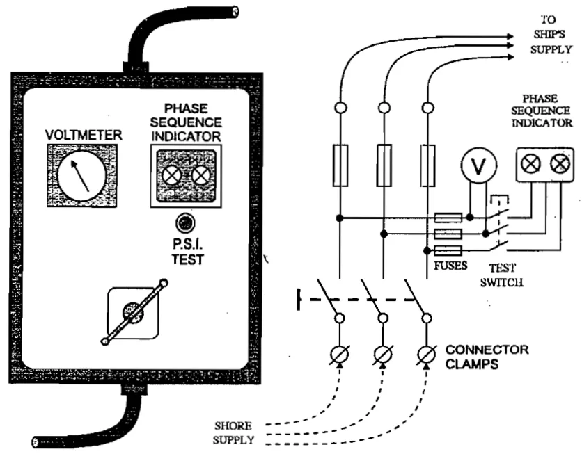
- The shore supply connection — the point at which the ship can be fed from the quay instead of from its own generators.
The shore supply connection
When a ship is in port and shut down, its electrical load is often supplied from the shore rather than by running a generator. The shore supply connection brings a cable from the quay to a dedicated breaker on the switchboard. The interlocks around it are the important part:
- The shore supply and the ship's generators must not be connected together by accident. Closing the shore breaker onto a live board, or closing a generator breaker onto a live shore supply, means two unsynchronised supplies fighting each other. The interlocks exist to prevent exactly that, and they are tested, not assumed.
- The shore supply has a fixed frequency and voltage determined by the port, not by the ship. It cannot be adjusted, so the ship's equipment has to accept what it is given.
- The shore connection is protected against overload in the same way a generator feeder is, and the cable and its plugs are rated for the full ship's load that may be taken through them.
The single phasing problem
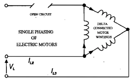
One failure mode of an alternating current supply is worth naming because it damages motors quietly rather than loudly. Single phasing is the condition in which one phase of a three-phase supply is lost — a blown fuse in one line, a broken connection, a contact that has burnt away. The machine continues to run, because two phases still give a rotating field, but the currents in the remaining phases rise sharply and the motor overheats.
The symptoms are easy to miss: the motor keeps running, the load seems normal, and only the heat gives it away. The protection against it is a device that senses the loss of a phase directly, or an overload relay that eventually sees the excess current. Because a three-phase motor on single phase can burn out without ever drawing enough current to trip a correctly-set overcurrent relay, the phase-failure protection has to be separate and deliberate.
Thermal overload protection
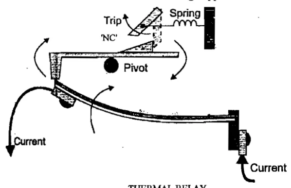
Motors and cables are protected against sustained excess current by thermal overload relays. The name describes the principle: the relay models the heating of the protected equipment, so a modest overload trips it slowly and a large one trips it quickly. This matches how insulation actually fails — by heat accumulated over time, not by a single instantaneous event.
A thermal overload relay is set to the rated current of the machine it protects, and the setting is part of the equipment's identity. Changing a motor without changing its overload setting, or setting the relay by guesswork, defeats the protection entirely.
4. Essential and non-essential load
Not all the ship's electrical load is equally important, and the switchboard is arranged to reflect that. Loads are divided into two groups:
- Essential loads are those needed to keep the ship safe and under control: the steering gear, the navigation equipment, the emergency lighting, the fire and bilge pumps, the alarms, the lubricating oil and cooling water pumps for the running machinery, and the starting air compressor. These are supplied from the main board and, in the event of a blackout, are the loads the emergency source must carry.
- Non-essential loads are everything that can be shed without endangering the ship: air conditioning, galley equipment, laundry, deck machinery that is not in use, cargo pumps at a convenient moment. These are the loads that are deliberately dropped when the available power falls short of the demand.
The reason for the split is that a generating set has a finite capacity and a finite transient capability. When a large load comes on and the set cannot carry it, something has to give. The engineer's choice, built into the switchboard, is that the non-essential loads give first.
5. The preferential trip
The mechanism that does this automatically is the preferential trip. When the load on the board exceeds what the running generators can supply — because a set has tripped, because a large motor has started, or because the load has simply grown — the preferential trip sheds non-essential loads in stages rather than letting the whole board collapse.
The staging is the point. Shedding everything at once would be a blackout by another name; shedding in stages gives the running sets time to recover between each step, and if they do recover, no further load is shed. The classic arrangement is three stages:
| Stage | Time after the overload is detected | What is shed |
|---|---|---|
| First | About 5 seconds | The least important loads — air conditioning, galley, laundry |
| Second | About 10 seconds | Heavier non-essential loads — deck machinery, non-running cargo equipment |
| Third | About 15 seconds | The remaining non-essential load |
If the overload clears before a stage is reached, that stage does not operate. The trip is progressive and self-limiting, and it is deliberately slow enough that a transient overload caused by a motor starting does not shed the board unnecessarily.
The whole arrangement depends on knowing which loads are which. A preferential trip with a mis-grouped feeder will shed the wrong thing, and the ship will be dark for no reason.
6. The automatic generating plant
A modern ship's generating plant runs largely without an engineer standing at the board. Understanding what the automation does is the same as understanding what the engineer used to do by hand. A fully automatic diesel generator plant performs eight functions:
- Preparation for starting — the standby set is kept warm, its lubricating oil is primed, and it is ready to start the moment it is called.
- Starting and stopping according to load demand — the automation decides when another set is needed and starts it, and when one can be stopped and stops it.
- Synchronisation of the incoming set — the incoming machine is brought to the correct speed, phase and voltage before its breaker is closed.
- Closure of the circuit breaker — the breaker is closed at the right instant, with no shock to either machine.
- Load sharing between alternators — once two or more sets are on the board, the load is divided between them in proportion to their ratings.
- Maintenance of supply frequency and voltage — the governors and AVRs hold the two quantities the system depends on.
- Protection of the engine and the alternator — faults trip the affected machine off the board before damage spreads.
- Preferential tripping of non-essential loads — as described above, the last line of defence before a blackout.
Keeping the standby sets warm
A set that has to start and take load within seconds cannot be cold. The standby generators are therefore kept ready by circulating them with the main engine cooling water, so that their jackets are already at working temperature. The pre-starting preparation is then limited to priming the lubricating oil — the engine is warm, the oil is at pressure, and starting is quick and reliable.
This is a small point with a large consequence. A cold engine started under load suffers wear and may not reach speed and voltage in time; a warm one does both. The cross-connection between the main engine and auxiliary engine jacket water systems described in the previous chapter exists partly for this reason.
Synchronising and load sharing
Bringing a second set onto a live board is the operation that most clearly separates a trained engineer from an untrained one. The incoming machine must match the running board in voltage, frequency and phase before its breaker is closed. Close it too early or too late in the cycle and the two machines are connected out of phase, which produces a violent current surge and can damage both alternators.
Once the breaker is closed, the load sharing is a matter of the governors. Two machines running in parallel divide the load according to their speed-droop settings, and the means by which this happens belongs to the governor chapter — it is a speed problem, not an electrical one. The electrical system simply provides the measurement of load that the governor acts on. The point to carry away is that load sharing is achieved through the engine governors, which is why the droop settings on parallel sets must match.
7. What follows for the auxiliary engine
The electrical plant imposes requirements on the engine that are worth stating plainly, because they explain much of how the engine is operated:
- The engine must hold speed tightly. Frequency is the engine's responsibility. A wandering governor is an electrical fault as far as the ship is concerned.
- The engine must accept load in steps without losing speed badly. The transient dip figures apply to frequency as well as voltage, and the engine's flywheel and governor together determine how well it copes.
- The engine must be ready to start and take load automatically. This is a requirement on the starting system, the prelubrication and the warming arrangements as much as on the engine itself.
- The engine must fail safe. If the engine trips, the breaker must open and the load must transfer or shed; if the electrical system faults, the engine must be protected from the consequences.
Everything from here in the set — the emergency generator, the operating procedures, the maintenance and the safety arrangements — follows from these four requirements.