
Two-Stroke Structure — Frame, Tie Rods, Liner, Piston & Crosshead
Eight parts from bedplate to block, tie rods holding the sandwich in compression, each shaped by the forces it must survive.
Key Principles at a Glance 6 points
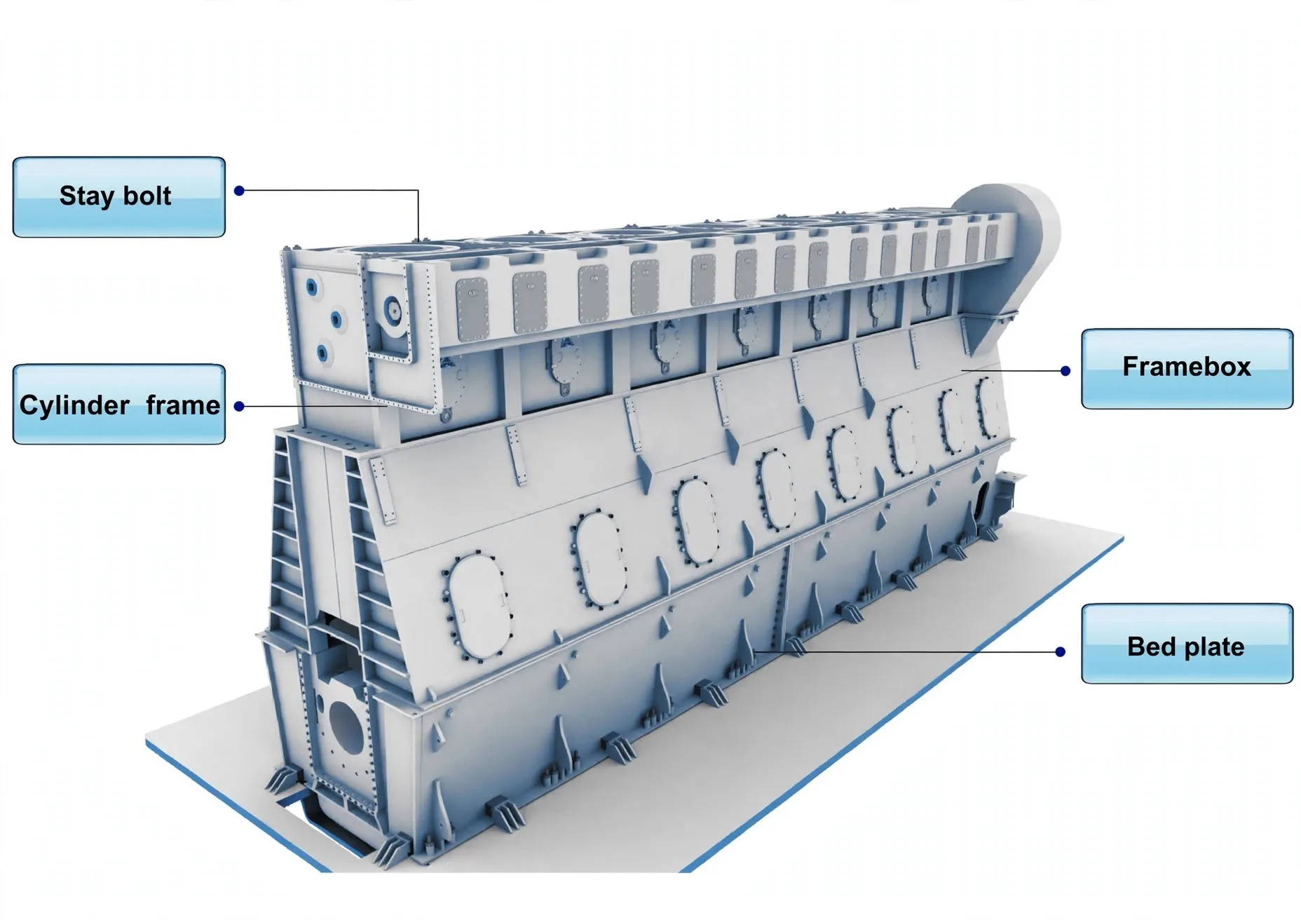
- Eight parts carry every load: bedplate, crankcase, crankshaft, rod, piston, liner, A-frame, entablature, cylinder block.
- Tie rods hold block, frame and bedplate in compression — 2n + 2 count, pinch screws kill transverse song, hydraulic tension to 1500 bar, breakage means slow down at once.
- The frame exists for stiffness: torque swings, gas forces and guide loads must never bend the shaft line — normalised 0.16% carbon steel at 430–500 N/mm².
- The cover seals combustion and carries five mountings: safety, fuel, indicator, starting and exhaust valves.
- Liners hang from the top and grow downward free; ports, timed oil bores and centrifugal pearlitic iron complete the design.
- The crosshead converts rod angularity into guide load so the liner sees concentric motion — telescopic pipes feed oil up, control devices watch it home.
1. The Load Path — Eight Parts, One Stiff Spine
Bedplate and crankcase, crankshaft and flywheel, connecting rod, piston, liner, A-frame, entablature, cylinder block — fixed structure holds alignment while moving parts fire. Torque fluctuation, gas forces and guide loads all attack transversely, so the frame is stiffened to keep crankshaft stress minimal, main bearings evenly loaded, piston and gear aligned, and fatigue at bay.
2. Cylinder Cover — Seal Plus Five Mountings
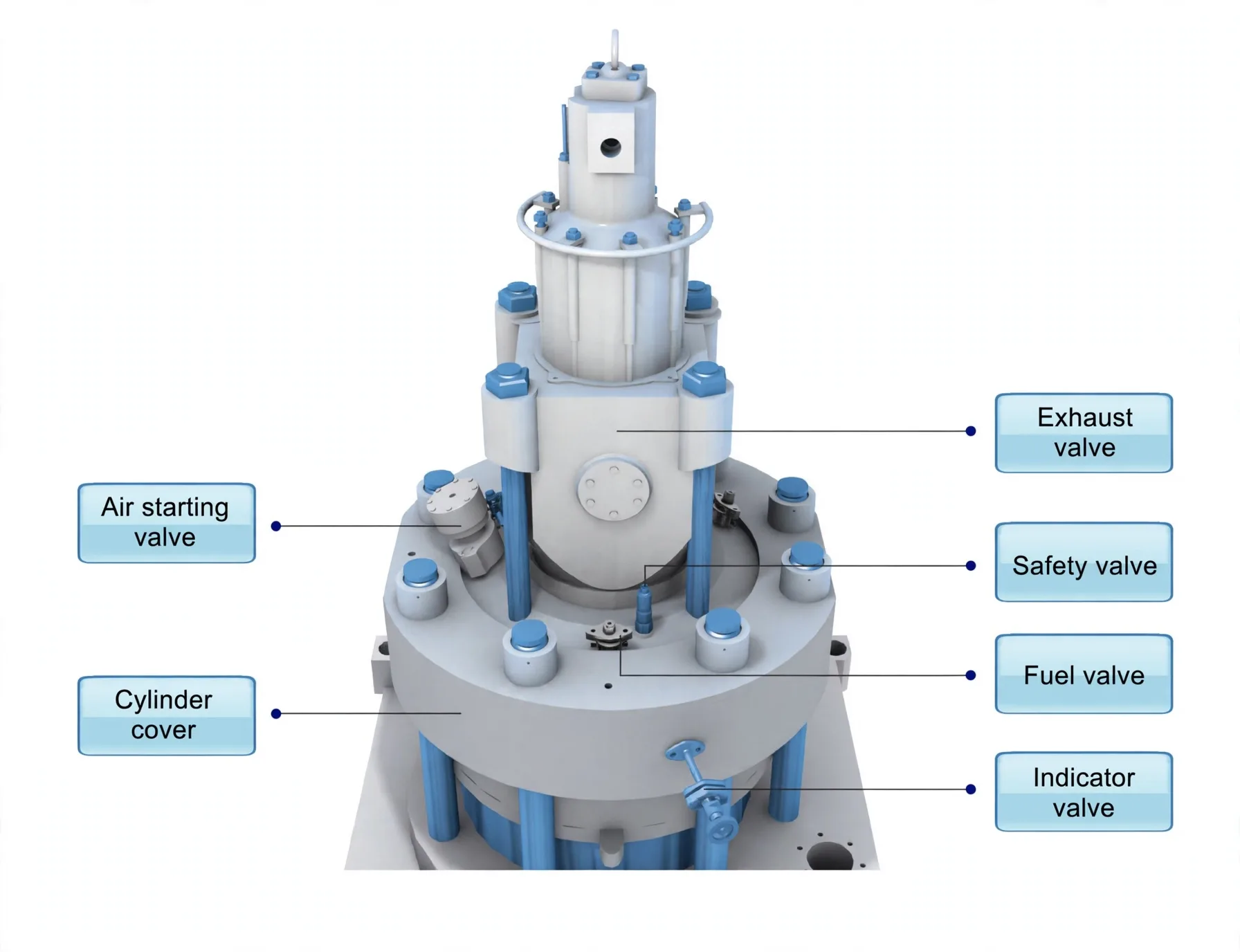
The cover closes the combustion space gas-tight against firing pressure, thermal stress, cyclic fluctuation and bolt preload — strong, jacket-water cooled, 0.16% carbon steel at 400–500 N/mm² with the fatigue strength to survive every cycle. It houses exactly five fittings:
- Safety valve — pressure relief of last resort.
- Fuel valve — injection into the chamber.
- Indicator valve — pressure diagrams and blow-through.
- Starting valve — air-start admission.
- Exhaust valve — gas exit on uniflow engines.
3. Liner & Piston — Ports, Growth, Cooling
The liner clamps at the top frame and grows downward free when hot — fixed top, sliding foot, or thermal stress would tear it. Its scavenge ports ring the lower wall, uncovered by the piston at bottom position, with timed lubrication bores around the circumference. Centrifugal casting in 3–3.5% carbon pearlitic grey iron keeps it dense and self-lubricating at the graphite flakes.
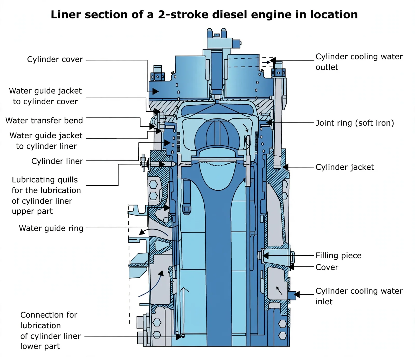
Piston cooling compared (Clyde p41): oil reaches the crown two ways — jet aimed at the under-crown, or shaker trays that fling it by piston motion (jet-shaker effect). MAN crowns are flame-hardened against the fire, Sulzer ring grooves ride in chrome; hot-corrosion crowns get Inconel-625 build-up, and the rubbing band below the rings runs phosphor bronze against the liner.
4. Crosshead — Sparing the Liner
Rod angularity drives the piston sideways with a thrust that grows as the liner wears — the crosshead intercepts it. Piston motion stays concentric in the bore while guide shoes dump the side load into the engine frame, which is why crosshead liners outlive trunk liners. Shoes run white-metal lined with shimmed alignment; the rod foot lands on hydraulic studs and nuts.
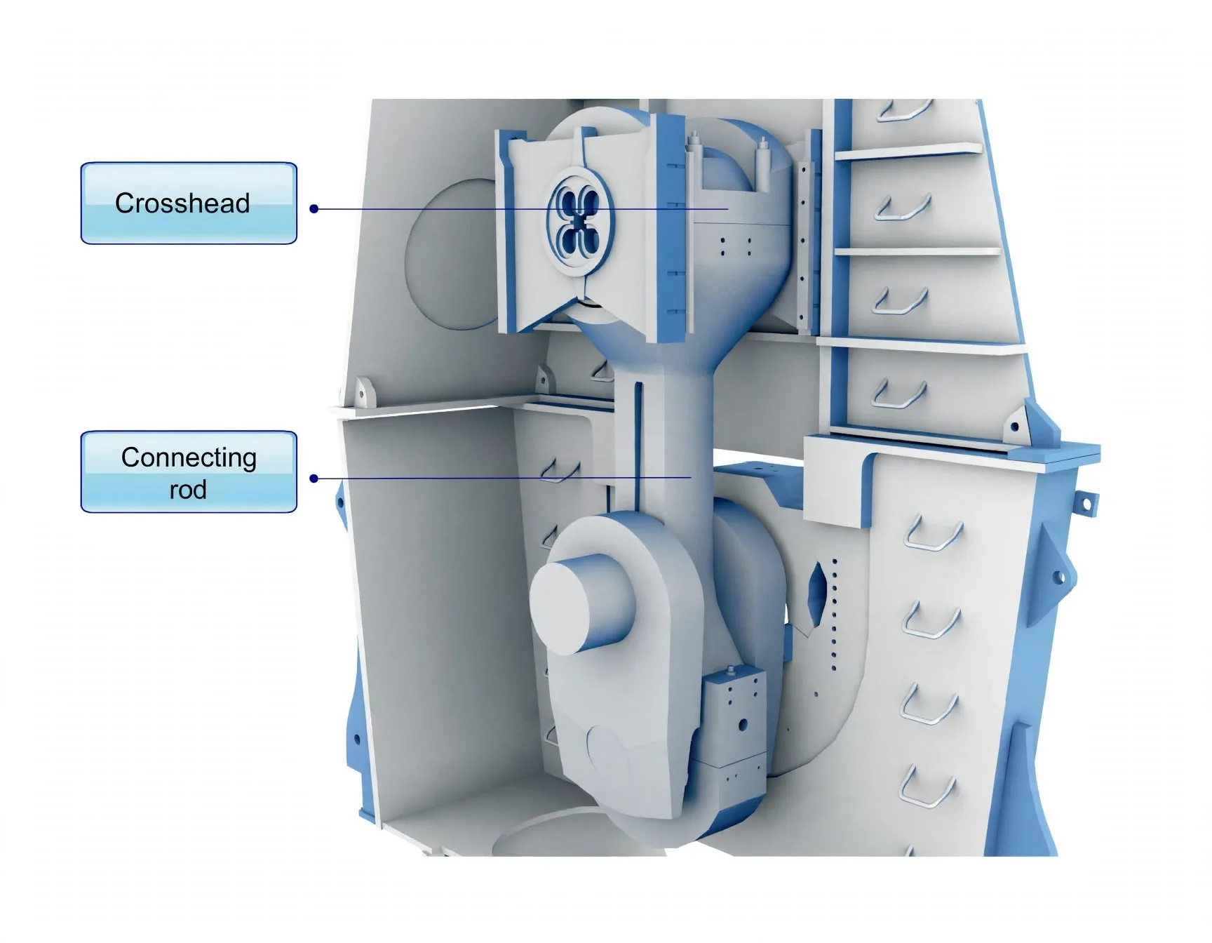
Oil climbs to the motion: a telescopic pipe on one guide shoe (counterweighted for its own mass) feeds crosshead, crankpin and piston cooling; the spent oil returns past a per-cylinder control device that checks temperature and flow before releasing it to the sump — the first sensor to report a bearing in distress.
5. Tie Rods — the Sandwich That Must Never Breathe
Idea in one line: firing pressure tries to blow the cylinder block off the bedplate every revolution — long resilient rods hold the whole engine in compression so the joint never opens, never frets, never cracks.
Each rod runs from bedplate to cylinder-block top beside the crankshaft centreline, stretching elastically as firing load peaks and relaxing between — count 2n + 2 with a chain casing (n = cylinders), 2n without a camshaft to enclose. Three duties in one rod: fatigue strength for millions of cycles, bending stress kept off the transverse girders, and the firing force delivered straight down to main bearings and frame:
Stop transverse song. Pinch screws at the foot of the cylinder jacket, on antinodes 120° apart, hand-tightened then lock-nutted to maker torque — a singing rod fatigues at its neck.
Tension by the book. Hydraulic jack elongates the stud, nut follows home — about 1500 bar on the M/E parts, tightened 900 first from the free end then 1500 from the opposite end (or the 4→5→3→6 sequence on small engines), on even keel in still air.
Prove the line. Crankshaft deflections re-read immediately after — tension changes the shaft line, and the gauge is the receipt.
Slack, overtightened, scavenge-fired, grounded or collided rods break at neck, bottom or middle — the mating faces weep lube oil. Slow the engine at once: an opened sandwich hammers itself apart. Power and MEP sag, bolts fret. Middle breaks lift out from the top after the head comes off.