
Marine Crankshafts — Builds, Bedplate, Chocks & Alignment
Why a 300-tonne shaft comes in pieces, what steel it sleeps on, and the fourteen reasons alignment fails.
Key Principles at a Glance 6 points
- Nobody forges 300 tonnes in one piece — large shafts assemble from separate forgings; only small engines get solid single pieces.
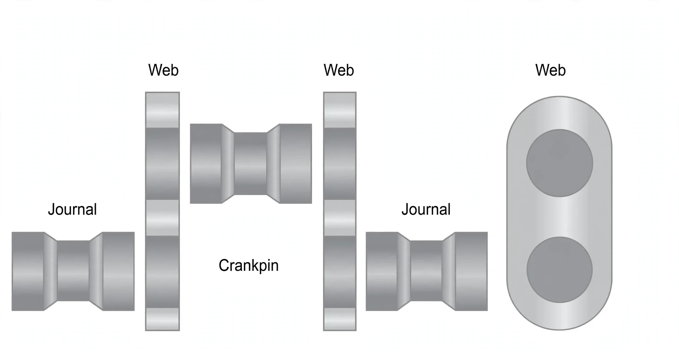
- Fully-built shrinks every journal and pin into bored webs; semi-built forges webs-plus-pin as one throw and shrinks journals only.
- Semi-built wins on grain flow: continuous fibres round web into pin let webs run thinner and pins run hollow.
- Witness marks across every shrink fit are read at each crankcase inspection — stepped marks mean slip.
- Misalignment has fourteen documented roots from wiped bearings to hull deformation — deflection measurement finds whichever one is active.
- Bedplate box girders in 0.23% C steel carry the saddles; holding-down bolts tensioned and wedge-tested clamp it; epoxy chocks poured, dammed and cured freeze it — re-proved on hours.
1. Why Big Shafts Come in Pieces
Camshaft timing, firing order and every driven auxiliary hang off correct crankshaft rotation — and its failure stops the ship. Slow-speed shafts run plain carbon steel (0.2–0.4% C), faster engines alloy steel, but no forge on earth makes a 300-tonne crosshead shaft whole. Construction method is therefore a joining method, chosen per size:
2. Four Builds Compared
| Build | How it joins | Notes |
|---|---|---|
| Fully built | Separate webs, pins, journals — webs heated, parts shrunk in, grip on cooling | Oldest method; no dowel pins (stress risers forbidden); witness marks prove no slip |
| Semi-built | Two webs + pin forged as one throw; journals shrunk in | Modern large-engine standard — grain flows unbroken round web into pin, so webs go thinner and pins hollow; balance hoop stress against remaining material |
| Welded | Web-pin-half-journal forgings submerged-arc welded, stress-relieved, machined | Continuous grain, lighter and shorter — but capital cost killed it after a few successes |
| Solid | Forged or cast in one piece (multi-cylinder in flanged sections) | Small medium- and high-speed engines only |
Design loads are firing plus three cyclic stresses: misalignment bending, torsional vibration and axial vibration — every later measurement chapter exists because of this trio.
3. Deflection Watches the Bearings
Bearing wear or shaft bend opens and closes the webs as each throw turns. A dial gauge between webs at successive crank positions reads that breathing — even-keel ship, trim recorded, positive for opening, negative for closing — against maker maximums. The companion lesson covers the full five-position procedure; the companion MEP lesson covers the curve.
4. Fourteen Roots of Misalignment
When deflection condemns the alignment, hunt in this order. The gauge only tells you to look — each cause below is a different repair:
- Wiped main bearing.
- Slack foundation or main-bearing bolts.
- Cracked saddle or pockets.
- Deformed bedplate or transverse girder.
- Slack or broken tie bolts and chocks.
- Corrosion-weakened structure.
- Hull deformation or grounding.
- Crankcase explosion or fire damage.
- Worn stern-tube or intermediate bearings dragging the line.
- Excessive piston-assembly bending loads.
5. Bedplate, Holding-Down & Epoxy Chocks — the Foundation Holds the Line
Idea in one line: the shaft line is only as true as the steel it sleeps on — bedplate carries it, holding-down bolts clamp it, epoxy chocks freeze it to the hull.
Fabricated bedplate (Clyde). Longitudinal girders carry the main-bearing saddles, transverse girders tie them into a box — welded from 0.23% carbon steel, the low carbon that welds without cracking. Rajesh's lineage runs plate → box → fabricated: cast-iron boxes first, then longitudinal + transverse weldments, then the fabricated MAN B&W pattern with its bearing pockets and A-frame feet.
Tension the holding-down bolts. Torque to maker figure with jacking screws taking the weight first — Clyde's wedge-and-hammer test then proves seating: a tight wedge rings, a loose one thuds.
Pour the epoxy. Dam the gap, mix resin and hardener to plan, pour from one side only so air walks out ahead, cure 48 hours before loading — chock plans live in the manual, not in memory.
Re-check on schedule. Holding-down tightness re-proved at intervals (Rajesh: 1k → 4k → 8k → 12k → 16k → 20k hours, then every 4k) — a walking engine eats bearings, then the shaft line.
Slack holding-down shows as fretted chocks, weeping joints, drifting deflections and finally cracked bedplate or girders — the misalignment list in §4 names every downstream victim. Tie-rod tension above and holding-down tension below are one system: the sandwich in Two-Stroke Structure §5.