
What Is an Air Compressor and How Does It Work?
Why a compressor is not a pump, why 31 bar absolute is not 30 bar gauge, and why a stopped compressor is still dangerous.
Key Principles at a Glance 7 points
- A compressor raises gas pressure by supplying mechanical energy; because gas is compressible, pressure, volume, density and temperature all change, whereas a pump moves a near-incompressible liquid.
- Normal cylinder clearance falls in the range of about 4% to 16%, so actual free-air delivery is always less than geometric piston displacement.
- Pressure ratios must use absolute pressure: 8 bar gauge at 1 bar atmospheric is 9 bar absolute, giving a ratio of 9:1 and not 8:1.
- Clearance gas left at the end of discharge must re-expand before the suction valve can open, which is why clearance reduces the fresh charge admitted.
- Compression raises temperature because work is done on the gas, so cylinder cooling, intercooling, aftercooling and condensate drains are part of the compression process, not accessories.
- Compressed air is stored energy: a stopped compressor leaves pressure in the receiver, coolers, discharge pipe, cylinder and valve pockets, so isolate, blow down and verify zero pressure before opening anything.
- Capacity is meaningless without a reference condition, because the same mass of air occupies different volumes at different pressures and temperatures.
1. Learning objectives
Course position: Air-compressor sequence, Topic 1
Level: Foundation
Main question: What is an air compressor, how does it raise gas pressure, and where does it fit in an engineering system?
After studying this chapter, you should be able to:
- Define a compressor.
- Explain why gases can be compressed.
- Distinguish a compressor, blower, fan, and pump.
- Describe how compression raises pressure and temperature.
- Explain the difference between pressure, capacity, and stored-air volume.
- Describe the basic reciprocating-compressor action.
- Identify positive-displacement and dynamic compressors.
- Explain single-acting and double-acting compression.
- Explain why compressor capacity changes with pressure.
- Describe common marine uses of compressed air.
- Explain why compressed air has a real energy cost.
- Identify the main hazards of compressed-air systems.
- Build the foundation for later study of compressor valves, cooling, lubrication, control, maintenance, and troubleshooting.
2. The shortest definition
A compressor is a machine that receives air or another gas at a lower pressure and delivers it at a higher pressure.
It does this by supplying mechanical energy to the gas.
The compressor does not create air. It changes the pressure, density, temperature, and useful condition of air.
The main compressor reference describes compressors as machines used to move air and other gases from place to place. Because gases are compressible, compressors operate differently from liquid pumps.
3. Why air can be compressed
Air is a gas made of molecules separated by spaces.
When air is enclosed in a cylinder and the piston moves inward:
- The available volume decreases.
- The molecules occupy a smaller space.
- Molecular collisions with the cylinder wall increase.
- The pressure rises.
- The temperature generally rises because work has been done on the gas.
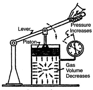
The indexed compressor text explains that reducing gas volume increases pressure and also increases temperature.
4. Gas compression is not liquid pumping
A pump normally handles a liquid that changes volume very little under ordinary pressure changes.
A compressor handles a gas whose volume and density change substantially.
| Feature | Pump | Compressor |
|---|---|---|
| Main fluid | Liquid | Gas |
| Compressibility | Very low | Significant |
| Main action | Raises liquid pressure | Raises gas pressure and density |
| Storage effect | Small fluid compression | Large stored-energy effect |
| Temperature change | Usually small | Often significant |
| Main hazards | Leakage, cavitation | Stored pressure, heat, fire, explosion |
| Typical examples | Feed pump, ballast pump | Starting-air compressor, control-air compressor |
A compressor may resemble a pump mechanically, especially a reciprocating machine, but its thermodynamic behaviour is different.
5. Compressor, blower, fan, and pump
The practical difference is mainly the pressure range and the intended duty.
5.1 Compressor
A compressor develops a relatively high pressure difference.
The main reference gives a broad compressor range from approximately 35 psi differential to very high pressures in special cases.
Applications include:
- Starting air
- Instrument air
- Service air
- Pneumatic tools
- Process gas
- Refrigerant vapour
- Breathing-air preparation, with special treatment
5.2 Blower
A blower generally handles a large gas volume at a lower pressure than a compressor.
Applications include:
- Combustion air
- Ventilation systems
- Scavenging support
- Aeration
- Low-pressure process gas
5.3 Fan
A fan produces enough pressure to overcome system resistance such as duct, grille, or static pressure.
Applications include:
- Engine-room ventilation
- Boiler air movement
- Cooling-air circulation
- Accommodation ventilation
5.4 Pump
A pump moves a liquid and raises its pressure.
These categories overlap in real industry, so the actual machine specification must be checked instead of relying only on the name.
6. What a compressor changes
When air passes through a compressor, several properties change:
- Pressure increases.
- Volume decreases for a trapped mass of gas.
- Density increases.
- Temperature increases during compression.
- Moisture may later condense during cooling.
- Mechanical energy becomes gas internal energy and pressure potential.
6.1 Pressure
Pressure is the force exerted by gas on a unit area.
For a gas inside a receiver, pressure represents stored energy that can perform work when released.
6.2 Volume
Volume is the space occupied by the gas.
A compressor cylinder repeatedly traps a volume of gas, reduces that volume, and delivers the gas at higher pressure.
6.3 Density
Density is mass per unit volume.
For the same mass of air:
- Higher pressure generally means greater density.
- Lower temperature generally means greater density.
- Higher density means more mass can be stored in a receiver of fixed volume.
6.4 Temperature
Compression raises temperature because mechanical work is transferred to the gas.
This is why compressors need:
- Cylinder cooling
- Intercoolers
- Aftercoolers
- Temperature alarms
- Condensate drains
7. Pressure terminology
A correct foundation requires clear pressure definitions.
7.1 Atmospheric pressure
Atmospheric pressure is the pressure exerted by the surrounding atmosphere.
It changes with:
- Altitude
- Weather
- Temperature
7.2 Gauge pressure
Gauge pressure is pressure above local atmospheric pressure.
A gauge reading of zero does not mean the system contains no pressure in an absolute sense. It means the pressure is approximately equal to the surrounding atmosphere.
7.3 Absolute pressure
Absolute pressure is measured from a perfect vacuum.
Absolute pressure must be used for:
- Pressure ratios
- Gas-law calculations
- Compressor performance calculations
- Stage-ratio calculations
7.4 Vacuum pressure
Vacuum pressure describes pressure below atmospheric pressure.
It is often expressed as:
- Inches of mercury
- Millimetres of mercury
- kPa below atmospheric pressure
- Absolute pressure directly
The compressor reference warns that the word “absolute” should not be omitted when a vacuum or pressure is stated.
8. Gauge pressure versus absolute pressure example
Suppose a receiver gauge reads 30 bar gauge and local atmospheric pressure is approximately 1 bar.
If a compressor suction pressure is 1 bar absolute and discharge pressure is 31 bar absolute:
Using 30 bar gauge directly would produce a slightly incorrect ratio.
The error becomes more important at lower pressures and when comparing compressor stages.
9. How a reciprocating compressor works
A reciprocating compressor uses a piston moving inside a cylinder.
Its essential parts are:
- Cylinder
- Piston
- Suction valve
- Discharge valve
- Crank mechanism
- Connecting rod
- Driver
The piston movement creates alternating suction and compression events.
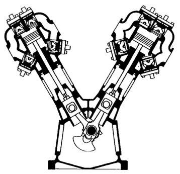
Basic sequence
The suction and discharge valves are normally automatic pressure-operated valves, not cam-operated valves.
10. Suction stroke
During the suction stroke:
- The piston moves away from the cylinder head.
- Cylinder volume increases.
- Cylinder pressure falls slightly below suction-line pressure.
- The pressure difference opens the suction valve.
- Air flows into the cylinder.
- The cylinder fills with air until the stroke ends.
The suction valve closes when cylinder pressure begins to rise above suction-line pressure during the return stroke.
What restricts suction?
- Dirty intake filter
- Small or long suction pipe
- Closed suction valve
- Excessive pressure drop
- Valve damage
- Ice or moisture, where applicable
- Foreign material
A restricted suction path reduces the mass of air entering the cylinder.
11. Compression stroke
During the compression stroke:
- The piston moves toward the cylinder head.
- The suction valve remains closed.
- The trapped air volume decreases.
- Pressure rises.
- Temperature rises.
- When cylinder pressure exceeds discharge-line pressure, the discharge valve opens.
The compression process requires power from the motor, engine, or other driver.
12. Discharge stroke
During the discharge portion of the stroke:
- Cylinder pressure exceeds discharge pressure.
- The discharge valve opens.
- The piston pushes compressed air into the discharge line.
- The discharge valve closes near the end of the stroke.
- A small amount of gas remains in clearance spaces.
The discharge valve must open and close correctly. A leaking discharge valve can cause:
- High temperature
- Poor capacity
- Increased power consumption
- Reverse flow
- Valve damage
13. Clearance volume
A small volume remains between the piston and cylinder head at the end of the stroke.
This is called clearance volume.
Clearance also exists in:
- Valve pockets
- Valve passages
- Cylinder-head spaces
- Port recesses
At the end of discharge, gas remains in this space. During the return stroke, the gas expands before the suction valve can open.
Clearance reduces the new volume of air admitted on the next suction stroke.
The compressor reference notes that normal clearance commonly falls within a range of approximately 4% to 16% for standard cylinders, although the actual value depends on design.
Do not treat clearance as a manufacturing defect. A controlled amount is necessary for safe operation.
14. Single-acting compression
A single-acting compressor compresses gas on one side of the piston.
The opposite side may be connected to the crankcase and may not be used for compression.
Advantages:
- Simpler construction
- Lower cost
- Easier maintenance
- Suitable for moderate capacity
Limitations:
- Lower delivery for a given cylinder size and speed
- More pulsating delivery
- Less compact at high capacity
15. Double-acting compression
A double-acting compressor compresses gas on both sides of the piston.
Each side has suction and discharge valves.
Advantages:
- Higher capacity for a given cylinder size
- Better use of piston movement
- Suitable for heavy-duty service
Additional requirements:
- Piston rod packing
- Crosshead or suitable guidance
- Careful alignment
- More valves
- More complicated maintenance
The main reference defines double-acting compressors as machines in which compression occurs on both sides of the piston, with valves at both cylinder ends.
16. Displacement: the volume swept by the piston
Piston displacement is the volume swept by the piston while moving through its stroke at rated speed.
For one cylinder, the swept volume per stroke is approximately:
where:
- D = cylinder bore
- L = piston stroke
For a single-acting cylinder, ideal displacement per minute is approximately:
where:
- N = number of working strokes per minute
For a double-acting cylinder, both sides contribute, subject to piston-rod area and actual design.
Important limitation
Piston displacement is not the same as actual free-air delivery.
Actual delivery is reduced by:
- Clearance
- Valve losses
- Leakage
- Heating of inlet air
- Piston-ring blow-by
- Pressure ratio
- Flow restrictions
The compressor reference explains that capacity varies with pressure conditions and that piston displacement alone does not represent actual delivered air.
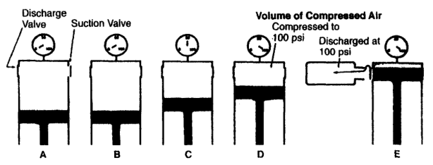
17. Capacity is not a fixed number
A compressor’s practical capacity changes with operating conditions.
For the same compressor and inlet condition:
- Higher discharge pressure usually reduces delivered capacity.
- Higher inlet temperature reduces air mass admitted per swept volume.
- Dirty valves reduce delivery.
- High clearance reduces delivery.
- Piston-ring leakage reduces delivery.
- Lower speed reduces displacement per minute.
This is why compressor ratings state the reference inlet and discharge conditions.
Capacity terms
- Piston displacement: geometric swept volume.
- Theoretical capacity: ideal volume based on displacement.
- Free-air delivery: equivalent volume referred to inlet or standard conditions.
- Actual delivered volume: volume at the pressure and temperature where it is measured.
- Mass flow: actual mass of air delivered per unit time.
18. Free-air delivery
Free-air delivery expresses compressed air as the volume it would occupy at specified inlet or reference conditions.
It allows different compressors to be compared fairly.
Without a reference condition, a statement such as “the compressor delivers 10 m³/min” is incomplete because the same mass of air occupies different volumes at different pressures and temperatures.
Always ask:
- At what inlet pressure?
- At what inlet temperature?
- Is the value actual volume or free-air volume?
- Is it measured before or after the cooler?
- Is it at full load or part load?
19. Positive-displacement compression
A positive-displacement compressor traps a quantity of gas in a closed or partly enclosed space, reduces or otherwise raises its pressure, and then discharges it.
Examples:
- Reciprocating piston
- Rotary vane
- Rotary screw
- Rotary lobe
- Scroll
- Liquid piston
The indexed compressor reference describes several compression methods, including trapping gas, reducing its volume, and pushing it into the discharge system.
Positive-displacement principle
Positive-displacement compressors can produce substantial pressure even at relatively low flow.
20. Dynamic compression
A dynamic compressor continuously accelerates gas and converts velocity into pressure.
Examples:
- Centrifugal compressor
- Axial compressor
The gas is not trapped in separate piston-cylinder pockets. Instead, rotating blades or impellers impart energy to a continuous flow.
Positive displacement versus dynamic
| Feature | Positive displacement | Dynamic |
|---|---|---|
| Gas handling | Intermittent pockets or chambers | Continuous flow |
| Pressure build-up | Volume reduction or enclosed compression | Velocity and diffusion |
| Flow pulsation | Common in reciprocating type | Usually continuous |
| Best use | High pressure, lower to medium flow | High flow, moderate pressure ratio |
| Main risks | Valve, ring, pulsation, clearance | Surge, stall, high-speed rotor issues |
The compressor classification diagram identifies displacement, rotary, reciprocating, radial, axial, and ejector families.
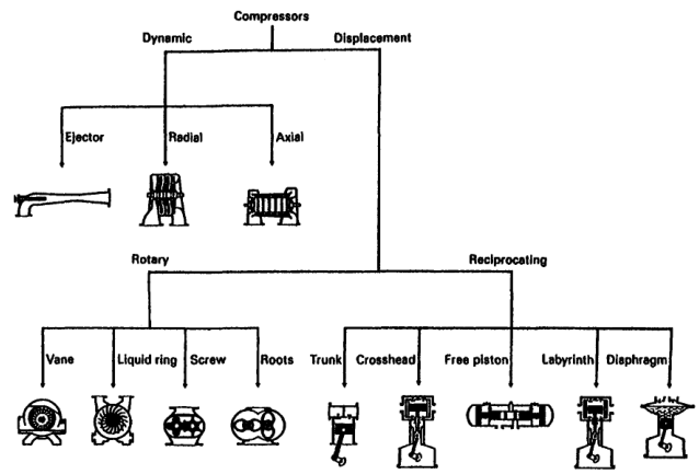
21. Rotary positive-displacement compressors
Rotary compressors trap gas between moving surfaces and carry or compress it toward the discharge.
Examples include:
- Sliding-vane compressor
- Liquid-piston compressor
- Straight-lobe compressor
- Helical or spiral-lobe compressor
- Screw compressor
Sliding vane
Vanes move radially in a rotor mounted eccentrically in a casing. Gas trapped between vanes is compressed and displaced.
Straight lobe
Two mating lobes trap and carry gas. Some lobe machines have little or no internal compression and rely on downstream pressure conditions.
Helical or screw
Intermeshing helical rotors trap gas and reduce its volume as it travels through the machine.
These machines are part of compressor literacy even when the main marine starting-air machine is reciprocating.
22. Refrigeration compressor as a related application
A refrigeration compressor also raises gas pressure, but its gas is refrigerant vapour rather than atmospheric air.
The compressor receives low-pressure gas from the evaporator and raises it to condenser pressure.
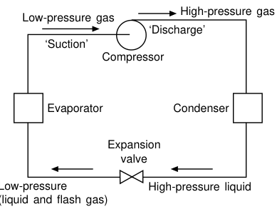
The refrigeration text defines the compressor’s purpose as accepting low-pressure dry gas from the evaporator and raising its pressure to condenser pressure.
The same broad principle applies:
- Gas enters at lower pressure.
- Mechanical work raises pressure.
- Gas temperature increases.
- The next component receives higher-pressure gas.
The application differs because refrigerant properties, oil return, condensation, evaporation, and superheat must be considered.
23. Air compressor versus refrigeration compressor
| Feature | Air compressor | Refrigeration compressor |
|---|---|---|
| Gas | Air or process gas | Refrigerant vapour |
| Main output | Compressed gas for use/storage | High-pressure refrigerant vapour |
| System destination | Receiver, tools, engine, control valves | Condenser |
| Moisture concern | Condensate from air | Refrigerant liquid/floodback |
| Oil concern | Oil carry-over and deposits | Oil return and refrigerant compatibility |
| Control | Receiver pressure and demand | Suction/discharge pressure, temperature, cooling load |
| Main hazard | Stored air pressure, heat, fire | High pressure, refrigerant, liquid slugging |
This chapter focuses mainly on air and process-gas compressors, while the refrigeration PDFs provide the related application comparison.
24. Why compression produces heat
Work is required to reduce gas volume and raise pressure.
That work appears partly as increased gas internal energy.
Therefore:
High temperature creates several problems:
- Lubricant breakdown
- Valve deposits
- Reduced valve life
- Cylinder wear
- Higher discharge-piping fire risk
- Increased power requirement
- Material damage
The compressor reference explains that high compression temperatures create design and operating limits.
25. Why multistage compression is used
A single stage can compress gas only within practical limits.
Multistaging divides the total pressure rise:
Benefits:
- Lower discharge temperature per stage
- Lower work than equivalent uncooled single-stage compression
- Improved volumetric efficiency
- Better mechanical and lubrication conditions
- Easier moisture removal between stages
- More practical high-pressure production
A stage should not be judged by discharge pressure alone. Interstage pressure reveals whether stages are sharing the work correctly.
26. Why cooling is part of compression
Cooling is not an optional accessory added after the compressor design. It affects the complete process.
Cylinder cooling
Protects cylinder, piston, rings, and lubricant.
Intercooling
Removes heat between stages and reduces the temperature entering the next stage.
Aftercooling
Removes final-stage heat before air enters the receiver or distribution system.
Condensate removal
Cooling can cause water vapour to condense. Separators and drains must remove it.
The compressor reference identifies aftercoolers and moisture separators as important parts of the compressed-air system.
27. Why lubrication is part of compressor function
Lubrication reduces:
- Bearing friction
- Crosshead friction
- Piston-ring wear
- Cylinder wear
- Packing wear
- Gear wear
However, oil must be controlled because oil entering compressed air can:
- Contaminate equipment
- Form deposits
- Increase fire risk
- Damage valves
- Affect instruments
- Reduce air quality
This creates two different design philosophies:
- Lubricated compressor
- Non-lubricated or oil-free compressor
Oil-free refers mainly to the compression chamber or delivered gas path. Bearings, crankcase components, and some packing arrangements may still require lubrication.
28. Why air quality matters
Compressed air is used directly by equipment.
Contaminants may include:
- Water
- Oil
- Rust
- Scale
- Carbon
- Dust
- Pipe debris
- Chemical vapour
Possible consequences:
- Control-valve failure
- Corrosion
- Starting-valve sticking
- Pneumatic-tool damage
- Instrument malfunction
- Cylinder wear
- Air-line blockage
The required air quality depends on the service.
| Service | Main concern |
|---|---|
| Starting air | Pressure, reliability, water, oil, safety |
| Control air | Dryness, cleanliness, stable pressure |
| Instrument air | Very low contamination and moisture |
| Workshop air | Adequate pressure and basic filtration |
| Process gas | Composition, purity, pressure, temperature |
29. Marine applications of air compressors
29.1 Main-engine starting air
High-pressure air is stored in receivers and admitted to engine starting valves.
The compressor must provide:
- Reliable receiver charging
- High pressure
- Safe discharge temperature
- Moisture removal
- Automatic cut-in and cut-out
- Redundancy
29.2 Auxiliary-engine starting air
Smaller engines may use the same starting-air system or a separate service.
29.3 Control air
Control air operates:
- Remote valves
- Pneumatic actuators
- Automatic regulators
- Engine-control equipment
- Safety systems
Control air must be dry and clean.
29.4 Service air
Service air supplies:
- Pneumatic tools
- Cleaning
- Deck machinery
- General engine-room services
Service air should not be confused with breathing air unless the complete breathing-air treatment system is approved.
29.5 Emergency air
Emergency air provides limited operation when normal power or compressors are unavailable.
The emergency supply must remain protected, available, and periodically tested.
30. Receiver: why compressed air is stored
A receiver stores compressed air and smooths pressure fluctuations.
It provides:
- Reserve capacity
- Reduced compressor cycling
- More stable system pressure
- Buffer during peak demand
- Moisture collection after cooling
- Reduced pulsation
An air receiver is a pressure vessel and must be designed, inspected, drained, and protected with a safety valve.
The compressor reference states that air receivers should be built to the applicable pressure-vessel code and reduce system pressure fluctuation.
31. Compressed air is stored energy
A stopped compressor does not mean the system is safe.
Pressure may remain in:
- Receiver
- Intercooler
- Aftercooler
- Discharge pipe
- Cylinder
- Valve pocket
- Drain line
- Hose
- Pneumatic actuator
Before maintenance:
- Stop the compressor.
- Isolate electrical power.
- Lock and tag the disconnect.
- Isolate air valves.
- Blow down receivers and coolers.
- Verify zero pressure.
- Confirm no automatic restart is possible.
The safety guidance specifically requires pressure release before opening compressor components.
32. Basic compressor system diagram
Every block has a purpose:
- Filter protects the machine.
- Compressor raises pressure.
- Intercooler reduces stage temperature.
- Separator removes condensate.
- Aftercooler reduces final discharge temperature.
- Receiver stores air and dampens pressure variation.
- Safety valve protects against overpressure.
- Distribution piping delivers usable air.
33. Compressor energy cost
Compressed air is not free.
Energy is consumed by:
- Motor or engine
- Mechanical drive
- Compression work
- Cooling-water system
- Lubrication system
- Air treatment
- Condensate removal
- Leakage in distribution piping
Power cost over the service life may exceed the initial compressor purchase cost.
Energy losses
- Intake restriction
- Valve leakage
- Piston-ring blow-by
- Intercooler fouling
- High discharge pressure
- Air leaks
- Poor capacity control
- Excessive unloading
- Wrong compressor size
- Poor maintenance
The correct compressor is not simply the one with the lowest purchase price.
34. Compressor selection begins with the service
Before selecting a compressor, determine:
- Required discharge pressure.
- Required air capacity.
- Duty cycle.
- Air quality.
- Power supply.
- Cooling-water availability.
- Space and weight.
- Foundation requirements.
- Control requirements.
- Maintenance capability.
- Redundancy requirement.
- Environmental conditions.
The compressor selection reference identifies discharge pressure, capacity, power supply, cooling water, space, weight, foundation, control, and maintenance cost as selection factors.
35. Basic terms to memorise
| Term | Meaning |
|---|---|
| Compressor | Machine that raises gas pressure |
| Suction | Low-pressure gas inlet |
| Discharge | High-pressure gas outlet |
| Pressure ratio | Absolute discharge pressure divided by absolute suction pressure |
| Capacity | Quantity of gas delivered per unit time |
| Piston displacement | Geometric volume swept by piston per unit time |
| Free-air delivery | Delivery referred to specified inlet/reference conditions |
| Clearance volume | Space remaining at end of piston stroke |
| Single-acting | Compression on one piston side |
| Double-acting | Compression on both piston sides |
| Intercooler | Cooler between compression stages |
| Aftercooler | Cooler after final compression stage |
| Receiver | Pressure vessel storing compressed gas |
| Separator | Removes condensed liquid from gas |
| Positive displacement | Gas trapped and compressed in a chamber |
| Dynamic compressor | Gas accelerated and converted to pressure |
| Suction valve | Admits gas to cylinder |
| Discharge valve | Allows compressed gas to leave |
| Volumetric efficiency | Actual intake compared with theoretical displacement |
36. Common beginner mistakes
Mistake 1: Calling a receiver a compressor
A receiver stores air. It does not compress air.
Mistake 2: Calling pressure capacity
Pressure is not the quantity delivered per unit time.
Mistake 3: Using gauge pressure in pressure ratios
Use absolute pressure.
Mistake 4: Assuming smaller volume always means lower temperature
Compression normally raises gas temperature unless heat removal offsets it.
Mistake 5: Assuming piston displacement equals delivery
Clearance, valves, leakage, pressure ratio, and temperature reduce actual delivery.
Mistake 6: Treating air as harmless
Compressed air stores dangerous energy.
Mistake 7: Thinking oil-free means maintenance-free
Oil-free cylinders still require filtration, cooling, inspection, and maintenance.
Mistake 8: Ignoring condensate
Cooling compressed air causes moisture to condense and collect.
37. First-principles review
Answer these without looking at the text:
- Why does reducing gas volume raise pressure?
- Why does compression raise temperature?
- What is the difference between a compressor and a pump?
- What is gauge pressure?
- What is absolute pressure?
- Why must absolute pressure be used for pressure ratios?
- What happens during a suction stroke?
- What causes the discharge valve to open?
- What is clearance volume?
- Why is actual delivery less than piston displacement?
- What is the difference between single-acting and double-acting?
- Why are intercoolers used?
- Why does condensate form?
- Why is an air receiver required?
- Why is compressed air dangerous after the compressor stops?
38. Worked conceptual example
Problem
A reciprocating compressor cylinder has a piston that moves outward. The suction valve is open and the cylinder is filling. What happens next?
Answer
As the piston moves inward:
- Cylinder volume decreases.
- The suction valve closes when cylinder pressure rises above suction-line pressure.
- Air is trapped in the cylinder.
- Pressure and temperature rise.
- The discharge valve opens when cylinder pressure exceeds discharge-line pressure.
- Compressed air flows into the discharge system.
- A small quantity remains in clearance volume.
This cycle repeats every working stroke.
39. Worked pressure example
Problem
A compressor receives air at 1 bar absolute and delivers it at 8 bar gauge. Atmospheric pressure is approximately 1 bar. Find the approximate pressure ratio.
Solution
Convert discharge pressure:
Suction pressure:
Pressure ratio:
The pressure ratio is approximately 9:1.
40. Worked displacement example
Problem
A single-acting cylinder has a bore of 100 mm, stroke of 150 mm, and operates at 300 working strokes per minute. Estimate geometric piston displacement before efficiency losses.
Solution
Convert dimensions to metres:
- D = 0.100 m
- L = 0.150 m
Swept volume per stroke:
Displacement per minute:
Actual free-air delivery will be lower because of clearance, valves, pressure ratio, heating, and leakage.
41. Revision questions with answers
Question 1
What is the main purpose of a compressor?
Answer: To raise the pressure of air or another gas by supplying mechanical energy.
Question 2
Why does compression raise temperature?
Answer: Mechanical work is done on the gas, increasing its internal energy.
Question 3
What is the main difference between a compressor and a pump?
Answer: A compressor handles a compressible gas; a pump normally handles an almost incompressible liquid.
Question 4
What is the difference between gauge and absolute pressure?
Answer: Gauge pressure is above atmosphere; absolute pressure is measured from a perfect vacuum.
Question 5
Why are pressure ratios calculated with absolute pressure?
Answer: Gas compression relationships use pressure measured from a vacuum reference.
Question 6
What opens the suction valve?
Answer: Cylinder pressure falling below suction-line pressure.
Question 7
What opens the discharge valve?
Answer: Cylinder pressure rising above discharge-line pressure.
Question 8
What is clearance volume?
Answer: The volume remaining between the piston and cylinder head, including valve-pocket space, at the end of the stroke.
Question 9
Why is actual delivery lower than piston displacement?
Answer: Clearance, valve losses, leakage, heating, and pressure conditions reduce delivery.
Question 10
What is double-acting compression?
Answer: Compression takes place on both sides of the piston.
Question 11
Why is an intercooler used?
Answer: To remove heat between stages and improve the efficiency and operating condition of multistage compression.
Question 12
Why does condensate form after cooling?
Answer: Cooling compressed air can reduce its ability to hold water vapour, causing moisture to condense.
Question 13
Why is an air receiver used?
Answer: To store compressed air, smooth pressure variation, and provide reserve capacity.
Question 14
Why is compressed air dangerous after shutdown?
Answer: Receivers, coolers, pipes, and cylinders may still contain stored pressure.
Question 15
Name four marine air services.
Answer: Main-engine starting air, auxiliary-engine starting air, control air, and service air.
42. Self-test scenarios
Scenario A — compressor pressure rises but delivery is poor
Possible reasoning:
- Check whether the discharge pressure is above the design condition.
- Check intake filter and suction restriction.
- Check suction valves.
- Check discharge valves.
- Check piston rings and clearance.
- Compare actual delivery with the rated reference condition.
Scenario B — discharge temperature is high
Possible reasoning:
- Check cooling-water or cooling-air flow.
- Check intercooler and aftercooler condition.
- Check discharge-valve leakage.
- Check pressure ratio.
- Check lubrication.
- Check carbon deposits and restricted discharge piping.
Scenario C — receiver pressure is low
Possible reasoning:
- Check compressor delivery.
- Check compressor speed.
- Check suction filter.
- Check valve condition.
- Check air leaks in the distribution system.
- Check demand and capacity-control setting.
- Check receiver drain or relief-valve leakage.
43. Chapter-one study checklist
- ☐ Define a compressor.
- ☐ Explain why gases are compressible.
- ☐ Distinguish compressor, blower, fan, and pump.
- ☐ Define gauge pressure.
- ☐ Define absolute pressure.
- ☐ Convert gauge pressure to absolute pressure.
- ☐ Explain suction, compression, and discharge strokes.
- ☐ Explain suction-valve and discharge-valve action.
- ☐ Define clearance volume.
- ☐ Distinguish piston displacement and actual delivery.
- ☐ Define single-acting and double-acting compression.
- ☐ Distinguish positive-displacement and dynamic compressors.
- ☐ Explain why compression produces heat.
- ☐ Explain why cooling and condensate removal are required.
- ☐ Explain the purpose of an air receiver.
- ☐ List marine compressed-air applications.
- ☐ State why compressed air remains dangerous after shutdown.
- ☐ Complete the pressure-ratio example.
- ☐ Complete the displacement example.
- ☐ Explain the system diagram without looking.