
Main Reciprocating Air Compressor Construction
Two machines on one frame: a running gear that turns rotation into reciprocation, and a gas end that squeezes air.
Key Principles at a Glance 7 points
- A reciprocating compressor is two machines on one frame, because the running gear converts rotation into reciprocation and the gas end converts that motion into a pressure rise.
- Load follows one path through driver, crankshaft, connecting rod, crosshead, piston rod and piston, so a fault at any link appears as abnormal motion, temperature or noise.
- Stroke is twice the crank radius, which fixes cylinder length and therefore the clearance space available.
- The crosshead exists to take the side thrust of the connecting rod so that the piston rod and packing see axial load only.
- Piston-rod packing seals the pressure boundary between cylinder and crankcase, while the oil scraper keeps crankcase oil out of the gas end.
- Valves are the most heavily worked parts in the gas end and the first place to look when capacity falls or discharge temperature rises.
- Any inspection begins with isolation, lock-out, venting and verified zero pressure, because the gas end holds stored energy with the driver stopped.
Learning objectives
By the end of this chapter you should be able to:
- identify the principal parts of a reciprocating compressor;
- trace the mechanical power path from driver to gas;
- explain the function of the frame, crankshaft, connecting rod, crosshead, piston rod, piston, and cylinder;
- distinguish the gas end from the running gear and explain why the separation matters;
- describe the construction of a typical single-acting and double-acting cylinder;
- identify the purpose of valves, heads, packing, oil scrapers, bearings, and cooling jackets;
- connect component condition with capacity, power, temperature, leakage, vibration, and reliability; and
- prepare a useful inspection sequence for a compressor that is operating abnormally.
1. The compressor as two connected machines
A reciprocating compressor has two interacting sections:
- The running gear or frame end, which receives power from the driver and converts rotary motion into reciprocating motion.
- The gas end, where the piston changes the gas volume and automatic valves control suction and discharge.
A typical flow of power is:
The gas path is separate:
This separation is especially important in heavy-duty and oil-free compressors. The frame may contain lubricating oil while the cylinder is designed to prevent that oil entering the compressed gas.
Modern heavy-duty continuous-service compressors may attach one or more cylinders to a horizontal or vertical frame. The same basic principles apply from a small single-cylinder air compressor to a large multistage, multiservice process machine.
2. Frame and crankcase
The frame supports the crankshaft bearings, crosshead guides, cylinders, lubrication system, and attached piping loads. It must remain stiff enough to preserve alignment under gas forces, inertia forces, thermal distortion, and foundation movement.
2.1 Frame functions
The frame:
- carries the main bearings;
- locates the crankshaft and crank throws;
- supports the crosshead guides;
- transmits cylinder and running-gear forces to the foundation;
- encloses or supports the crankcase lubrication system;
- provides inspection access;
- supports distance pieces and packing cases where fitted; and
- provides mounting surfaces for cylinders and auxiliary equipment.
A flexible or cracked frame changes the alignment between the crankshaft, crosshead, piston rod, and cylinder. The resulting failures may include packing leakage, piston-ring wear, cylinder rubbing, bearing distress, abnormal vibration, and high power consumption.
2.2 Material and construction
Frames may be cast or fabricated from steel or cast iron according to size, pressure, speed, and manufacturer practice. The important characteristics are stiffness, dimensional stability, resistance to fatigue, and accurate bearing and guide machining.
The frame must also tolerate repeated cyclic loading. A compressor does not apply a steady force: gas pressure and inertia forces vary every revolution. Local stress concentration around bearing saddles, cylinder attachments, and crosshead guides must therefore be controlled.
2.3 Crankcase enclosure
The crankcase retains lubricating oil and prevents contamination from entering the running gear. Covers and inspection doors permit examination of:
- main bearings;
- crankpin bearings;
- connecting rods;
- oil pump and strainer;
- crosshead shoes;
- crankshaft webs; and
- counterweights.
A crankcase breather or vent prevents excessive pressure caused by oil agitation, blow-by, or temperature rise. The vent arrangement must not permit unsafe oil mist release or allow dirt to enter.
2.4 Frame inspection points
During an inspection check for:
- cracks around bearing housings;
- fretting or movement at bolted joints;
- loose foundation or frame bolts;
- oil leakage;
- abnormal oil temperature or pressure;
- loose inspection covers;
- metal particles in the oil;
- evidence of water contamination; and
- paint or grout cracks indicating movement.
A frame defect should not be dismissed as a cosmetic problem. The frame is the reference structure for the entire compressor.
3. Crankshaft
The crankshaft converts the driver’s continuous rotary motion into the reciprocating motion required by the pistons. It is usually a steel forging supported by at least two main bearings. More throws and cylinders generally require additional bearing support.
3.1 Principal features
A crankshaft includes:
- main journals;
- crankpins;
- webs;
- counterweights or balance weights;
- keyways or coupling connection;
- oil passages where pressure lubrication is used; and
- thrust-locating arrangements where required.
The crank throw determines the piston stroke:
where L is stroke and r is crank radius.
3.2 Crank throws and cylinder arrangement
The angular arrangement of crank throws determines piston phase, firing or compression sequence, torque uniformity, and balance. A multistage compressor must also coordinate the motion of low-pressure and high-pressure pistons so that interstage flow remains stable.
Throw arrangement affects:
- primary and secondary inertia forces;
- rocking couples;
- torque variation;
- flywheel requirement;
- vibration transmitted to the foundation; and
- the timing of suction and discharge events.
3.3 Counterweights
Counterweights offset a portion of the rotating and reciprocating mass effects. They may be integral with the shaft or separately bolted. They cannot eliminate every unbalanced force in every arrangement, but correct balancing reduces bearing load, foundation reaction, and vibration.
A missing, loose, cracked, or incorrectly installed counterweight is a serious defect. It can cause rapid bearing damage, shaft fatigue, or catastrophic failure.
3.4 Crankshaft inspection
Inspect journals and crankpins for:
- scoring;
- overheating or discolouration;
- cracks;
- taper and out-of-round;
- wiped bearing material;
- blocked oil holes; and
- fretting at fitted components.
Measure bearing clearances according to the manufacturer’s procedure. Excess clearance reduces oil-film reliability and can produce low oil pressure, knocking, and inaccurate shaft position. Insufficient clearance can cause seizure when the shaft expands or the oil viscosity rises during a cold start.
4. Main bearings
Main bearings support the crankshaft and maintain its centreline in the frame. They may be:
- anti-friction rolling bearings;
- plain sleeve bearings; or
- older adjustable babbitted two- or three-piece bearings.
The bearing type determines lubrication, inspection, clearance measurement, permissible load, and replacement procedure.
4.1 Bearing duties
A main bearing must:
- carry radial gas and inertia loads;
- maintain crankshaft alignment;
- transmit torque reactions into the frame;
- operate with an oil film or rolling contact; and
- accommodate thermal expansion and shaft movement within limits.
4.2 Bearing failure symptoms
Possible symptoms include:
- low oil pressure;
- rising bearing temperature;
- metallic particles in the sump;
- rumbling or knocking noise;
- increased vibration;
- crankshaft runout or movement; and
- oil discolouration.
Bearing symptoms must be correlated with oil condition, pressure, temperature, alignment, and load. A low oil-pressure alarm may be caused by a pump or filter problem, but it may also indicate internal bearing leakage.
5. Connecting rod
The connecting rod links the crankpin to the crosshead. It transmits both compression and tension loads as the crank rotates. The rod is subjected to alternating forces, bending effects from misalignment, and cyclic fatigue.
5.1 Construction
A connecting rod normally has:
- a crankpin end with bearing shell or bushing;
- a shank designed for stiffness and fatigue strength;
- a crosshead-end connection;
- bolts or a fitted connection; and
- provisions for oil supply where required.
The crankpin bearing must accommodate the changing load direction and maintain an oil film. Connecting-rod bolts are critical load-bearing parts; incorrect tightening or damaged threads can cause rapid failure.
5.2 Rod-load significance
Gas pressure on the piston and inertia of the reciprocating mass combine to produce rod load. Rod load is usually checked in both compression and tension because the limiting condition can differ by design.
Excessive rod load may result from:
- excessive discharge pressure;
- liquid entering the cylinder;
- overspeed;
- incorrect cylinder pressure balance;
- valve failure;
- excessive piston mass or altered components; and
- abnormal clearance or impact.
A rod-load limit is a design protection limit, not a target operating value.
6. Crosshead
A crosshead guides the piston rod and separates the rod’s reciprocating motion from the angular motion of the connecting rod. In heavy-duty compressors the crosshead is mounted in a guide and carries sliding shoes or shoes with replaceable wear surfaces.
6.1 Why a crosshead is used
Crosshead construction:
- guides the piston rod accurately;
- prevents the connecting rod from applying side thrust directly to the piston;
- allows a narrow piston and greater valve area;
- permits a longer stroke and higher capacity;
- separates crankcase oil from the cylinder gas end;
- reduces piston slap and ring wear;
- supports stronger piston designs and higher pressure; and
- permits compression at both ends of a piston in double-acting machines.
The crosshead therefore does more than merely guide motion. It is a key part of alignment, lubrication control, and cylinder cleanliness.
6.2 Crosshead shoes and guides
The shoe-to-guide clearance must allow an oil film and thermal expansion without permitting excessive movement. Excessive clearance can produce knocking and piston-rod misalignment. Insufficient clearance can cause heating and seizure.
Inspect for:
- wiped or scored shoe surfaces;
- uneven contact pattern;
- embedded dirt or metal;
- guide wear;
- loose shoe retainers;
- oil starvation; and
- evidence of frame distortion.
A crosshead problem can appear at the gas end as packing leakage or abnormal ring wear. Always investigate alignment before replacing only the visible worn part.
7. Piston rod
The piston rod transmits crosshead force to the piston. It must withstand alternating tension and compression, maintain straightness, and provide a reliable sealing surface through the packing case.
7.1 Requirements
The rod must have:
- adequate fatigue strength;
- a precise diameter and surface finish through the packing;
- corrosion and wear resistance;
- correct fit at the crosshead and piston;
- sufficient stiffness to prevent bending; and
- a secure locking arrangement.
Rod material, diameter, length, composition, and fastening arrangement are selected for compressor load and piston design.
7.2 Rod runout and alignment
Rod runout is the deviation of the rod from its intended centreline during rotation and reciprocation. Excessive runout may indicate:
- bent piston rod;
- incorrect crosshead alignment;
- frame distortion;
- cylinder misalignment;
- loose piston or crosshead connection; or
- foundation movement.
Consequences include packing leakage, rapid packing wear, piston-ring damage, cylinder scoring, and increased friction.
7.3 Tail rods and opposed plungers
Special high-pressure designs may use tail rods or opposed plungers. These arrangements balance forces or permit extreme pressure service, but they add seals, alignment requirements, and inspection points. High-pressure cylinders can use opposed single-acting ends as identical stages or as different stages with different bore sizes.
8. Piston
The piston forms the moving boundary of the compression space. Its face, rings, rider bands, rod connection, and end clearances determine sealing, capacity, friction, and mechanical reliability.
8.1 Single-acting piston arrangement
A single-acting piston compresses gas on one side only. The opposite side may be open to the crankcase or separated by a packing arrangement. The cylinder has suction and discharge events at the active end.
8.2 Double-acting piston arrangement
A double-acting piston compresses gas on both sides. Each end has suction and discharge valves, and the piston rod passes through a packing case at one end. Double acting increases capacity for a given frame size but adds valves, packing, cooling, and clearance considerations.
8.3 Piston rings and rider rings
Piston rings reduce leakage between piston and cylinder. Rider rings support the piston weight and limit metal-to-metal contact, especially in non-lubricated designs. Ring material and profile must match gas cleanliness, temperature, pressure, cylinder material, and lubrication.
Ring failure can cause:
- reduced capacity;
- increased discharge temperature;
- gas blow-by;
- crankcase contamination;
- increased power;
- cylinder scoring; and
- abnormal noise.
8.4 Piston clearances
End clearance prevents the piston from striking the head at the end of the stroke. Radial clearance allows thermal expansion and ring operation. Both must remain within the manufacturer’s limits.
Too little end clearance causes impact risk. Too much clearance reduces capacity because more gas remains trapped and re-expands during suction. Incorrect piston position can result from a wrong rod length, incorrect packing adjustment, changed gasket thickness, or a shifted crosshead.
9. Cylinder barrel and heads
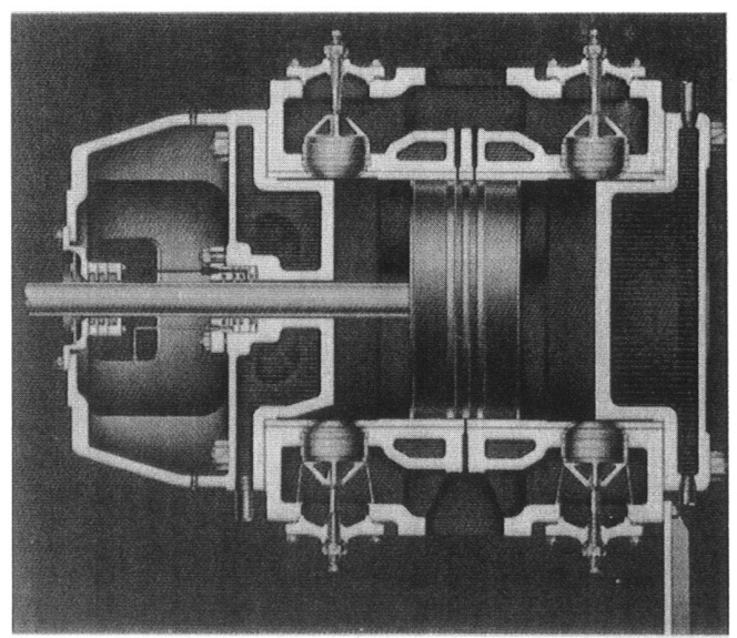
A typical double-acting cylinder consists of a barrel, usually water-jacketed, with front and rear heads. The rear head may be integral with the barrel or a separate bolted component. Heads can also be water-cooled to remove compression heat.
9.1 Cylinder barrel
The barrel provides the precision bore in which the piston and rings operate. It must resist:
- internal gas pressure;
- cyclic pressure loading;
- thermal gradients;
- valve impact and pulsation forces; and
- wear from rings and rider bands.
The bore finish must retain the intended surface condition without excessive roughness that damages rings or excessive smoothness that prevents suitable oil retention where lubrication is required.
9.2 Cylinder heads
Cylinder heads close the compression space and provide access to valves, clearance pockets, cooling passages, and pressure connections. They must withstand pressure and thermal cycling while maintaining gasket sealing.
Head inspection includes:
- cracks and erosion;
- gasket-face condition;
- loose or damaged valve pockets;
- blocked water passages;
- corrosion or scale;
- incorrect clearance-pocket operation; and
- evidence of piston contact.
9.3 Water jackets
Water jackets remove heat from the barrel and heads. Fouling, sludge, scale, air pockets, low flow, or excessive water temperature reduces heat transfer. The result is higher gas temperature, poorer lubrication, deposits, shorter valve life, and greater maintenance cost.
The cooling system must be drained and protected against corrosion and freezing where applicable. Chemical cleaning should follow the equipment maker’s procedure because aggressive treatment can damage materials or seals.
9.4 Valve pockets
Valve pockets locate suction and discharge valves around the cylinder barrel or in the heads. Their shape influences flow restriction, clearance volume, valve accessibility, and heat transfer.
A valve pocket that is damaged, incorrectly gasketed, or assembled with the wrong valve can create leakage, reverse flow, poor capacity, or excessive temperature.
10. Compressor valves
Automatic compressor valves open when the pressure difference across the valve overcomes spring and inertia forces, and close when the pressure difference reverses. They do not normally require a mechanical cam.
10.1 Suction valves
The suction valve admits low-pressure gas during the suction part of the cycle. It must open with low pressure loss and close securely before compression begins.
A leaking suction valve allows compressed gas to return to the suction passage. It reduces capacity, increases temperature, and may cause an abnormal indicator card.
10.2 Discharge valves
The discharge valve opens when cylinder pressure exceeds discharge pressure by enough to overcome spring and valve inertia forces. It must close without excessive impact when cylinder pressure falls.
A leaking discharge valve allows high-pressure gas to return to the cylinder during expansion or suction. The cylinder may run hot, lose capacity, and consume more power.
10.3 Valve construction
Common valve elements include:
- seat;
- plate, ring, or poppet;
- springs;
- guard or lift limiter;
- retainer; and
- gasket or sealing arrangement.
Valve materials must tolerate pressure pulsation, temperature, impact, corrosion, and any liquid or solid contamination in the gas.
10.4 Valve condition and compressor performance
Valves are often among the most maintenance-sensitive compressor components. Check for:
- broken springs;
- cracked or worn plates;
- damaged seats;
- carbon or oil deposits;
- excessive lift;
- incorrect spring arrangement;
- dirt or liquid damage; and
- incorrect installation orientation.
Valve leakage is a gas-end problem, but its effects appear throughout the machine: lower capacity, higher power, high discharge temperature, altered interstage pressure, and possible driver overload.
11. Piston-rod packing
Packing seals the moving piston rod where it passes through the cylinder head or distance piece. It prevents compressed gas escaping to the crankcase or atmosphere and prevents frame oil entering the cylinder.
11.1 Packing functions
Packing must:
- limit gas leakage;
- tolerate rod reciprocation;
- maintain sealing as pressure changes;
- control oil migration;
- dissipate heat; and
- permit inspection and adjustment.
Packing may be lubricated, minimally lubricated, or non-lubricated. Cooling may use oil, water, or a thermosiphon arrangement depending on the design.
11.2 Packing leakage
Packing leakage may be caused by:
- worn rings;
- scored or rough piston rod;
- rod runout;
- incorrect ring orientation;
- inadequate cooling;
- incorrect lubrication;
- loose or distorted packing case; or
- excessive cylinder pressure.
Do not cure packing leakage by tightening until the rings overheat. Excessive loading increases friction and can score the rod. Determine whether the root cause is alignment, cooling, lubrication, or wear.
11.3 Distance piece
A distance piece separates the cylinder from the frame. It provides space for packing, oil scrapers, vents, drains, and inspection. In oil-free or hazardous service it helps prevent frame oil from reaching the gas end and provides a controlled leakage path.
12. Oil scraper and crankcase separation
An oil scraper limits the movement of crankcase oil along the piston rod. It works with the distance piece and packing arrangement to control oil carryover.
The design objective is not merely to keep the crankcase dry. It is to maintain the required balance between:
- crankcase lubrication;
- rod-surface oil film;
- cylinder cleanliness;
- packing life; and
- allowable gas contamination.
A damaged scraper can produce oil carryover, contaminated gas, carbon deposits, valve sticking, and unsafe discharge piping. In an oil-free gas end, the frame can still be pressure-lubricated, but the separation system must be maintained.
13. Lubrication system
The running gear commonly uses a forced or splash lubrication system. Its components may include:
- oil sump;
- gear or plunger oil pump;
- suction strainer;
- pressure-regulating valve;
- oil filter;
- cooler;
- pressure gauge and switch;
- distribution passages; and
- drain and sampling points.
13.1 Lubrication objectives
Proper lubrication:
- reduces bearing and shoe wear;
- removes heat;
- flushes wear particles toward the filter;
- prevents corrosion;
- reduces friction; and
- provides an oil film between loaded surfaces.
Oil quality, cleanliness, viscosity, level, pressure, and temperature all matter. Incorrect oil can produce low pressure, foaming, deposits, seal incompatibility, or bearing damage.
13.2 Oil contamination
Inspect for:
- water or coolant in the oil;
- fuel or process gas dilution;
- metallic particles;
- carbon and sludge;
- abnormal viscosity; and
- foaming.
A clean oil sample does not prove that all bearings are healthy, but a contaminated sample is a strong reason for investigation.
14. Flow path through a two-stage compressor
A typical two-stage machine operates as follows:
Every item introduces a pressure drop or maintenance requirement. A restriction before the low-pressure cylinder reduces mass flow. A restriction between stages changes the stage pressure ratio. A restricted aftercooler or discharge line increases final discharge pressure and power.
The construction of the compressor cannot be separated from the construction of its accessories.
15. Component-to-symptom diagnosis
| Observation | Components to inspect first | Reason |
|---|---|---|
| Low capacity | Suction valve, discharge valve, piston rings, inlet filter, unloaders | Gas is not entering, being retained, or being delivered correctly |
| High discharge temperature | Discharge valve, cooling jacket, intercooler, rings, excessive pressure ratio | Heat is generated or not removed |
| High power | Discharge restriction, leaking valves, high pressure, bearing friction, poor intercooling | More compression or mechanical work is required |
| Oil in delivered air | Packing, scraper, distance piece, cylinder lubrication | Oil is crossing from the frame or being over-supplied |
| Packing leakage | Rod finish, rod runout, packing rings, cooling, alignment | The moving seal is overloaded or worn |
| Frame knock | Main bearing, crankpin bearing, crosshead, loose bolt, oil starvation | Running-gear clearance or support is abnormal |
| Cylinder knock | Valve, piston-to-head clearance, broken ring, liquid entry | Impact or abnormal valve movement is occurring |
| Excessive vibration | Foundation, balance, piping, pulsation, alignment, bearings | Dynamic forces are not being controlled |
| Low oil pressure | Pump, strainer, relief valve, filter, bearing clearance, oil level | Supply or internal leakage problem |
| High interstage pressure | High-pressure suction restriction, low-pressure discharge valve, cooler blockage | Gas cannot pass normally between stages |
The table is a starting point, not permission to replace parts without measurements. Confirm the symptom with pressure, temperature, vibration, oil, and capacity data.
16. Inspection sequence
A safe inspection sequence is:
- isolate and lock out the driver;
- close and lock suction, discharge, and cooling-water valves as required;
- vent and depressurise all cylinders, coolers, separators, and receivers;
- verify zero pressure with suitable instruments;
- inspect external leakage, piping support, foundation, and guards;
- record oil level, pressure, temperature, and contamination;
- inspect valves and valve pockets;
- measure piston end clearance and rod position where required;
- inspect packing and scraper leakage;
- check crankcase, bearings, crosshead shoes, and connecting rods;
- inspect cooling passages and drains;
- reassemble with correct torque, gaskets, clearances, and valve orientation;
- rotate by hand where permitted; and
- restart under controlled conditions while monitoring pressure, temperature, vibration, and oil.
Never open a cylinder or valve pocket while trapped pressure or hot coolant may remain. A compressor can contain energy after the driver is stopped.
17. Construction comparison: trunk piston and crosshead
| Feature | Trunk piston | Crosshead compressor |
|---|---|---|
| Piston guidance | Piston skirt guides in cylinder | Crosshead and shoes guide rod |
| Frame-to-cylinder separation | Less complete | Strong separation through distance piece |
| Typical size | Small and moderate duty | Heavy-duty and high-pressure service |
| Oil control | More direct interaction with cylinder | Better separation of frame oil and gas end |
| Piston side thrust | Carried by piston skirt | Mostly carried by crosshead guide |
| Double-acting use | Limited by arrangement | Well suited to heavy-duty double acting |
| Maintenance emphasis | Skirt, rings, cylinder lubrication | Shoes, rod alignment, packing, distance piece |
Neither arrangement is universally superior. Selection depends on pressure, capacity, gas cleanliness, speed, duty cycle, cost, and maintenance capability.
18. Revision questions
- What are the two principal sections of a reciprocating compressor?
- Trace the mechanical power path from driver to piston.
- What functions does the compressor frame perform?
- Why are crankshafts counterweighted?
- What is the relationship between crank radius and piston stroke?
- What are the functions of main bearings?
- What loads act on a connecting rod?
- Why is a crosshead used in heavy-duty compressors?
- What symptoms can result from excessive crosshead-guide clearance?
- What requirements apply to a piston rod passing through packing?
- Distinguish single-acting and double-acting piston arrangements.
- What are the functions of piston rings and rider rings?
- Why is piston end clearance necessary?
- What is the function of a water jacket?
- Where may compressor valves be installed?
- What is the effect of a leaking suction valve?
- What is the effect of a leaking discharge valve?
- What functions does piston-rod packing perform?
- Why is a distance piece used?
- What does an oil scraper prevent?
- List the principal parts of a forced-lubrication system.
- Why can a cooling-water restriction cause high discharge temperature?
- What components should be inspected for oil in delivered air?
- Why must piping and foundation be considered part of compressor construction?
- Give a safe sequence for opening a compressor cylinder.
19. Self-test scenarios
Scenario A — low capacity and hot discharge
A two-stage compressor delivers less air than normal and the high-pressure cylinder is hot. Check high-pressure suction and discharge valves, interstage pressure, intercooler flow, and piston-ring condition. A failed low-pressure discharge valve can also alter the interstage condition and starve the high-pressure cylinder.
Scenario B — oil at the receiver
Inspect cylinder lubrication rate, piston-rod packing, oil scraper, distance-piece drains, and rod surface. Do not immediately blame the crankcase oil alone. Confirm whether the oil is entering through the gas end or being carried through a failed separator.
Scenario C — frame knock after maintenance
Check oil pressure, main-bearing and crankpin clearances, connecting-rod bolts, crosshead shoes, counterweights, and foundation bolts. Confirm that no component was assembled with incorrect clearance or torque.
Scenario D — repeated packing failure
Measure piston-rod runout and alignment before installing another packing set. Inspect rod finish, packing cooling, distance-piece venting, and cylinder support. Repeated replacement without correcting alignment is symptom treatment, not repair.
20. Summary
A reciprocating compressor is a precision load-bearing structure, not simply a piston in a cylinder. The frame and foundation establish alignment. The crankshaft and connecting rod transmit power. The crosshead and piston rod guide and transmit the reciprocating load. The piston, rings, cylinder, heads, and valves control the gas. Packing, oil scrapers, distance pieces, cooling jackets, lubrication, and separators preserve the boundaries between gas, oil, heat, and atmosphere.
Each component affects system performance. Valve leakage reduces capacity and raises temperature. Ring leakage increases re-compression and power. Poor cooling damages valves and lubricant. Bearing, crosshead, or foundation problems create vibration and alignment errors. Correct diagnosis therefore follows the energy and gas paths through the complete machine.