
Gas Laws, Air Properties and Moisture in Compressors
Why 40 degrees is not twice 20 degrees, and where the water in your air receiver comes from.
Key Principles at a Glance 7 points
- Gas-law calculations must use absolute temperature in kelvin: 20 degrees C and 40 degrees C are 293.15 K and 313.15 K, not a ratio of 2.
- Dry air is about 78% nitrogen, 21% oxygen and 1% argon by volume, and near 20 degrees C at standard pressure its density is about 1.2 kg/m3.
- Air at 40 degrees C has only about 93.6% of the density of air at 20 degrees C at the same pressure, so a hotter intake delivers less mass for the same swept volume.
- At high altitude density falls sharply, and air at high elevation can hold only about 74% of sea-level density, which directly cuts compressor capacity.
- Water vapour is part of the intake air, and cooling after compression reduces the air's capacity to hold it, which is why condensate forms in intercoolers, aftercoolers, separators and receivers.
- Isothermal compression needs the least work and adiabatic the most, and real machines follow a polytropic path between the two.
- Multistaging with intercooling pushes the real path towards isothermal, which is the thermodynamic reason it saves power.
1. Learning objectives
Course position: Air-compressor sequence, Topic 3
Level: Foundation and applied theory
Main question: How do pressure, volume, temperature, density, and moisture change in compressor systems?
After studying this chapter, you should be able to:
- Explain how gas molecules create pressure.
- State Boyle’s law.
- State Charles’ law.
- State Amonton’s pressure-temperature law.
- Combine the gas laws into the ideal-gas equation.
- Use absolute temperature in gas-law calculations.
- Explain density and specific volume.
- Explain how pressure and temperature affect compressor capacity.
- Explain humidity and water vapour in intake air.
- Explain partial pressures in air mixtures.
- Distinguish isothermal, adiabatic, isentropic, and polytropic compression.
- Explain why real compression produces heat.
- Explain why intercooling saves power.
- Explain why condensate forms after cooling.
- Apply gas laws to compressor and receiver examples.
- Recognise the limits of ideal-gas assumptions.
2. What is air?
Air is a mixture of gases, primarily:
- Nitrogen — approximately 78% by volume
- Oxygen — approximately 21% by volume
- Argon — approximately 1%
- Variable water vapour
- Small quantities of carbon dioxide and other gases
The compressor reference identifies air as a gas mixture rather than a single pure substance.
This matters because the air entering a compressor may contain:
- Water vapour
- Salt near the sea
- Dust
- Oil mist
- Industrial gases
- Exhaust contamination
- Micro-organisms
The compressor does not remove all of these automatically. Intake filtration, cooling, separation, and drainage are required.
3. Gas molecules and pressure
Gas molecules are separated by distances large compared with their molecular size.
They move continuously and collide with the walls of the container.
Pressure is the combined effect of these collisions over an area.
If the molecules:
- Move faster, pressure tends to increase.
- Strike the wall more often, pressure tends to increase.
- Are confined to a smaller volume, collision frequency increases.
- Are cooled at constant volume, pressure tends to decrease.
The compressor reference explains pressure using molecular motion and collision frequency.
4. Temperature and molecular speed
Temperature is related to the average kinetic energy of molecules.
When heat is added to gas in a fixed volume:
- Molecules move faster.
- Collisions occur more frequently.
- Collisions are more energetic.
- Pressure increases.
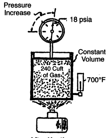
If the gas is allowed to expand while heated, the pressure may remain approximately constant while volume increases.
Therefore, every gas-law calculation must state which variables are constant.
5. Absolute temperature
Gas-law calculations require absolute temperature.
The SI absolute temperature scale is Kelvin:
For Fahrenheit-to-Rankine conversion:
Never use Celsius or Fahrenheit directly in a ratio such as:
Example
20°C and 40°C are not a temperature ratio of 40/20 = 2.
Convert first:
The absolute-temperature ratio is approximately 1.068, not 2.
6. Boyle’s law
For a fixed mass of ideal gas at constant temperature:
Therefore:
If volume decreases, pressure increases in inverse proportion.
Example
A gas occupies 1.0 m³ at 1 bara and is compressed isothermally to 0.5 m³.
The refrigeration reference gives the same principle: when volume is reduced to half at constant temperature, pressure doubles.
7. Boyle’s law and the compressor cylinder
During the compression stroke, the piston reduces the gas volume.
If temperature were constant, Boyle’s law would predict the pressure rise directly.
A real compressor differs because temperature also rises.
Therefore actual compression pressure rises more quickly than a simple isothermal calculation would predict when heat cannot escape immediately.
8. Charles’ law
At constant pressure, the volume of a fixed mass of ideal gas is proportional to absolute temperature:
or:
If gas is heated at constant pressure, it expands.
If gas is cooled at constant pressure, it contracts.
Example
A gas occupies 0.75 m³ at 20°C and is heated at constant pressure to 90°C.
Convert temperatures:
Then:
This worked example is given in the refrigeration reference.
9. Amonton’s law
At constant volume, pressure is proportional to absolute temperature:
or:
If a sealed receiver is heated, its pressure rises even though the amount of gas and volume remain constant.
Example
A sealed receiver contains air at:
- p₁ = 8 bara
- T₁ = 293.15 K
The temperature increases to 333.15 K.
This is why a receiver’s safety valve and temperature exposure must be considered even when the compressor is stopped.
10. Combined gas law
For a fixed mass of ideal gas:
This combines Boyle’s, Charles’, and Amonton’s relationships.
Rearrangements include:
All pressure values must be absolute, and all temperature values must be absolute.
11. Ideal-gas equation
The combined gas law can be expressed as:
where:
- p = absolute pressure
- V = gas volume
- m = gas mass
- R = specific gas constant
- T = absolute temperature
For air:
The refrigeration reference gives the ideal-gas equation and a volume calculation for a known mass of gas.
Rearranged forms
12. Ideal-gas volume example
Problem
Find the volume occupied by 5 kg of air at:
- Pressure = 1 standard atmosphere = 101,325 Pa absolute
- Temperature = 25°C
- R = 287 J/(kg· K)
Solution
Convert temperature:
Use:
This is the example presented in the refrigeration reference.
13. Density and specific volume
Density is mass per unit volume:
Specific volume is volume per unit mass:
From the ideal-gas equation:
Therefore:
- Higher absolute pressure increases density.
- Higher absolute temperature decreases density.
- Lower pressure decreases density.
- Lower temperature increases density.
Why density matters to a compressor
A piston sweeps a geometric volume, but the mass of air admitted depends on density.
This explains why a compressor’s mass delivery changes with altitude and intake temperature even when speed and cylinder dimensions remain constant.
14. Density example
Problem
Estimate air density at:
- p = 101325 Pa
- T = 20°C = 293.15 K
- R = 287 J/(kg· K)
Solution
This agrees with the common engineering approximation of approximately 1.2 kg/m³ for dry air near 20°C and standard pressure.
15. Effect of altitude on density
At altitude:
- Atmospheric pressure is lower.
- Air density is lower at the same temperature.
- A naturally aspirated compressor cylinder admits less mass per stroke.
- Free-air delivery must be corrected.
- The compressor may require derating or larger low-pressure cylinders.
The compressor reference explains that lower absolute intake pressure at altitude affects cylinder sizing and compressor derating.
Example
At 20°C:
- Sea-level pressure = 101.3 kPa
- High-altitude pressure = 75 kPa
Approximate density ratio:
At the same temperature, the high-altitude air has approximately 74% of the sea-level density.
16. Effect of intake temperature on capacity
At constant suction pressure:
If intake temperature rises:
- Density decreases.
- Less mass enters per swept volume.
- Mass delivery decreases.
- Volumetric capacity expressed at intake conditions may appear similar, but mass capacity falls.
- Compression power and temperature behaviour may change.
Example
Compare air at 20°C and 40°C at the same pressure.
The air at 40°C has approximately 93.6% of the density at 20°C.
This is why cool, clean intake air improves compressor mass delivery.
17. Gas mixtures and partial pressure
Air is a mixture of gases.
Dalton’s law states that the total pressure of a mixture is the sum of the partial pressures of its components:
Each gas contributes pressure as if it occupied the volume alone at the same temperature.
This matters because atmospheric air contains water vapour.
The dry-air pressure is:
The refrigeration reference introduces Dalton’s law for gas mixtures.
18. Water vapour in intake air
Atmospheric air may be unsaturated or saturated with water vapour.
Relative humidity
Relative humidity compares actual water-vapour partial pressure with saturation vapour pressure at the same temperature:
Saturated air
At 100% relative humidity, air contains the maximum water vapour possible at that temperature before condensation begins.
Dew point
The dew point is the temperature at which the air becomes saturated when cooled at approximately constant pressure.
If compressed air is cooled below its dew point, water condenses.
19. Why condensate forms in compressor systems
The intake air contains water vapour.
During compression:
- Pressure rises.
- Temperature initially rises.
- The gas then passes through an intercooler or aftercooler.
- Cooling reduces the vapour-holding capacity of the air.
- Liquid water forms in the separator or cooler drain.
Condensate must be removed because it can:
- Damage valves
- Corrode receivers and piping
- Wash away lubricant
- Cause liquid slugging
- Freeze in some systems
- Contaminate control equipment
20. Condensate and liquid carryover
Liquid carryover is especially harmful to compressor valves.
A liquid slug is difficult to compress. It can:
- Break valve seats
- Bend valve elements
- Damage piston components
- Destroy lubrication films
- Cause hydraulic shock
- Produce sudden load changes
The compressor reference warns that liquid carryover from intercoolers or process systems causes premature failure and recommends regular draining of interstage separators.
Drainage requirements
- Intercooler drain
- Aftercooler drain
- Moisture separator drain
- Receiver drain
- Low points in piping
Automatic traps can be used, but they must be maintained and provided with safe bypass or manual-drain arrangements where required.
21. Isothermal compression
Isothermal compression occurs at constant temperature.
The heat produced by compression is removed continuously.
This requires ideal or highly effective cooling.
Advantages
- Lowest theoretical compression work for a given pressure ratio
- Lowest final temperature
- Reduced thermal stress
Practical limitation
Perfect isothermal compression is difficult because heat transfer cannot be instantaneous throughout the cylinder.
It is a useful theoretical reference, not the exact real compressor cycle.
22. Adiabatic compression
Adiabatic compression occurs with no heat transfer to or from the gas during the compression process.
For an ideal gas:
where k is the ratio of specific heats.
Adiabatic compression produces a larger temperature rise than isothermal compression for the same pressure ratio.
The compressor reference defines adiabatic compression as compression without heat transfer.
Practical meaning
A fast compression stroke behaves closer to adiabatic than isothermal because there is little time for heat to leave the gas during the stroke.
23. Isentropic compression
Isentropic compression is an ideal reversible adiabatic process.
It assumes:
- No heat transfer
- No friction
- No internal losses
- No valve losses
- No leakage
It is used as a reference for calculating ideal discharge temperature and compressor efficiency.
A real compressor requires more work than an ideal isentropic compressor for the same pressure ratio.
24. Polytropic compression
Polytropic compression follows:
where n is the polytropic exponent.
The value of n depends on heat transfer and actual compressor behaviour.
Typical conceptual relationships:
- Isothermal: n = 1
- Adiabatic ideal gas: n = k
- Real compression: n lies between or may differ depending on cooling and losses
The compressor reference defines polytropic compression as a process in which heat is transferred at a defined relationship while the compression line follows PV^n = C.
25. Comparison of compression processes
| Process | Heat transfer | Temperature rise | Work requirement |
|---|---|---|---|
| Isothermal | Heat removed continuously | Lowest | Lowest ideal work |
| Isentropic | No heat transfer, reversible | Ideal adiabatic rise | Reference ideal work |
| Adiabatic | No heat transfer | High | Higher than isothermal |
| Polytropic | Practical heat transfer | Real intermediate value | Practical work reference |
| Real compressor | Heat transfer, friction, leakage, valve losses | Actual rise | Greater than ideal reference |
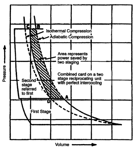
26. Why multistaging approaches isothermal compression
A multistage compressor divides compression into steps.
Between stages, an intercooler removes heat.
Benefits:
- Lower discharge temperature
- Lower total work
- Reduced pressure differential per cylinder
- Lower frame and running-gear loads
- Better volumetric efficiency in later stages
- Condensate removal between stages
The compressor reference identifies power saving, discharge-temperature limitation, and pressure-differential limitation as the main reasons for multistaging.
27. Adiabatic discharge temperature
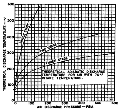
An ideal adiabatic or isentropic temperature relationship is commonly written:
Therefore:
where pressures are absolute and temperatures are Kelvin.
Actual discharge temperature depends on:
- Compressor efficiency
- Cooling
- Valve condition
- Pressure ratio
- Cylinder size
- Speed
- Gas properties
- Leakage
The indexed compressor reference provides a theoretical adiabatic discharge-temperature graph for air.
28. Temperature example using an ideal relationship
Problem
Air enters at:
- T₁ = 300 K
- p₁ = 1 bara
It is compressed isentropically to:
- p₂ = 8 bara
Assume k = 1.4.
Solution
Convert to Celsius:
This is an ideal reference. Actual discharge temperature may differ because of cooling, losses, and machine design.
29. Compression work and heat
The first law of thermodynamics states that energy cannot be created or destroyed.
During compression:
The compressor reference states that mechanical energy changes into gas energy during compression.
This energy balance explains why:
- The motor requires significant power.
- Discharge gas becomes hot.
- Coolers must reject heat.
- Bearings and valves experience thermal loads.
- Poor cooling increases operating risk.
30. Heat rejection in compressor systems
Heat leaves through:
- Cylinder jackets
- Cylinder fins
- Intercooler cooling water
- Aftercooler cooling water or air
- Compressor frame
- Discharge piping
- Radiated heat
Poor cooling causes:
- Higher discharge temperature
- Oil breakdown
- Carbon deposition
- Shorter valve life
- Higher power
- Fire risk
The compressor cooling reference identifies high temperature as a cause of less-effective lubrication, valve deposits, shorter valve life, increased cylinder maintenance, and discharge-piping fire risk.
31. Air properties and compressor capacity
For a given displacement:
Since:
then:
Therefore delivered mass changes if:
- Suction pressure changes.
- Suction temperature changes.
- Gas composition changes.
- Compressor displacement changes.
- Volumetric efficiency changes.
This is why compressor capacity must specify reference conditions.
32. Actual cubic feet per minute and intake cubic feet per minute
The compressor reference uses terms such as:
- ICFM — intake cubic feet per minute
- ACFM — actual cubic feet per minute
- Free-air capacity
- Piston displacement
Actual capacity may refer to volume at intake conditions.
The same mass flow can occupy different actual volumes at different pressure and temperature conditions.
Always distinguish:
- Volume at suction condition
- Volume at standard condition
- Volume at discharge condition
- Mass flow
33. Gas composition and specific gas constant
For a pure ideal gas:
The specific gas constant R depends on the gas molecular mass.
For a gas mixture, effective properties depend on composition.
Changes in gas composition affect:
- Density
- Compression work
- Discharge temperature
- Specific-heat ratio
- Valve loading
- Compressor capacity
- Material compatibility
The compressor reference notes that gas characteristics can strongly influence compressor-type selection.
For ordinary atmospheric air, use air properties. For process gases, use the correct gas data.
34. Humidity and compressor inlet air
Humidity changes the composition and density of intake air.
At the same total pressure and temperature:
- Humid air contains water vapour.
- The dry-air partial pressure is lower.
- The dry-air mass per volume changes.
- More water may condense after compression and cooling.
High humidity can increase:
- Condensate quantity
- Corrosion risk
- Water carryover
- Drain load
- Control-air drying requirement
Intake location matters on a ship because sea spray and engine-room vapour can contaminate the air filter.
35. Relative humidity and dew point
Relative humidity
where:
- p_v = actual water-vapour partial pressure
- p_vs = saturation vapour pressure at the same temperature
Dew point
When humid air is cooled to its dew-point temperature:
- Relative humidity reaches 100%.
- Further cooling produces condensation.
Compressor implication
Aftercooler outlet temperature should be low enough to remove a predictable fraction of moisture, and separator drains must be kept functional.
36. Air density at altitude example
Problem
Estimate dry-air density at:
- Pressure = 575 mbar absolute
- Temperature = −10°C
- Sea-level reference density = 1.2 kg/m³ at 1013.25 mbar and 20°C
Method
Using proportional gas-law correction:
Convert:
Then:
The refrigeration reference gives this altitude-density example.
37. Gas-law limitations
The ideal-gas equation is an approximation.
It works well when:
- Pressure is not extremely high.
- Temperature is sufficiently above condensation conditions.
- Gas behaves approximately ideally.
- The composition is known.
At high pressure or near phase change, use a compressibility factor:
where:
- Z = compressibility factor
For ordinary shipboard air-compressor calculations at moderate pressure, ideal-gas approximations are often useful. For high-pressure process gas or refrigerant calculations, real-fluid data may be necessary.
38. Compression of air versus compression of refrigerant
Air normally remains a gas through ordinary starting-air compression.
A refrigerant may change between:
- Superheated vapour
- Saturated vapour
- Liquid
- Two-phase mixture
The refrigeration system must prevent liquid entering the compressor because liquid is difficult to compress and may cause slugging.
The same gas-law foundation applies, but refrigerant calculations require saturation tables and phase-property data.
39. Pressure-volume diagram
A real reciprocating-compressor cycle includes:
- Compression
- Discharge
- Re-expansion of clearance gas
- Suction
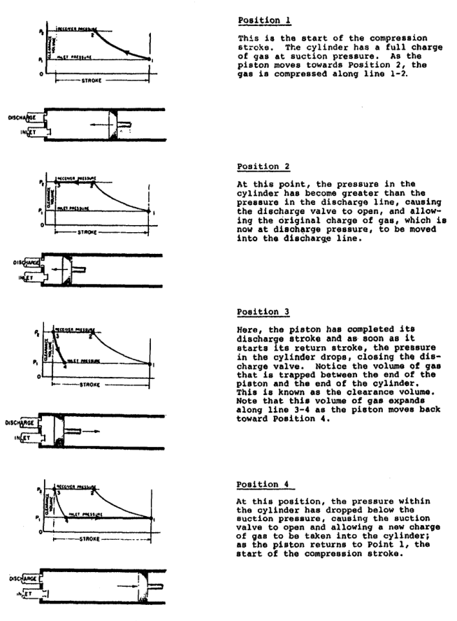
At the end of discharge, clearance gas expands during the return stroke. Suction begins only when cylinder pressure falls below suction-line pressure.
Gas laws explain the shape of this cycle:
- Compression raises pressure as volume falls.
- Expansion lowers pressure as volume rises.
- Actual lines differ because of heat transfer and losses.
40. Ideal p-V cycle interpretation
Position 1
Cylinder is filled with gas at suction pressure.
Position 1 to 2
Piston compresses gas. Suction valve is closed.
Position 2
Cylinder pressure reaches discharge pressure. Discharge valve opens.
Position 2 to 3
Compressed gas leaves the cylinder.
Position 3
Piston reaches the end of discharge. Clearance gas remains.
Position 3 to 4
Clearance gas expands as piston returns.
Position 4
Cylinder pressure falls below suction pressure. Suction valve opens.
Position 4 to 1
Fresh gas enters.
41. Why real compression differs from ideal compression
Real machines have:
- Valve pressure drop
- Valve delay
- Heat transfer
- Piston-ring leakage
- Cylinder leakage
- Clearance volume
- Pressure pulsation
- Mechanical friction
- Intercooler pressure drop
- Non-ideal gas behaviour
Therefore actual power and discharge temperature differ from simple equations.
Use ideal equations for:
- First estimates
- Conceptual understanding
- Comparing trends
- Detecting impossible results
Use manufacturer data and measured performance for final decisions.
42. Multistage compression and gas-law reasoning
Suppose air is compressed from 1 bara to 16 bara.
A single stage experiences the full ratio:
Two equal-ratio stages each experience approximately:
Three equal-ratio stages each experience approximately:
Smaller stage ratios generally reduce peak temperature and improve power performance when effective intercooling is provided.
The compressor reference explains that multistaging saves power, limits discharge temperature, and limits pressure differential.
43. Why cooling changes the gas-law path
Without intercooling, the gas entering the next stage remains hot.
With intercooling:
- Temperature falls.
- Specific volume decreases.
- The next-stage cylinder can receive denser gas.
- Compression work decreases.
- Final discharge temperature decreases.
Perfect intercooling returns the gas to approximately its original suction temperature between stages.
Actual intercooling includes:
- Cooler approach temperature
- Water-temperature variation
- Fouling
- Pressure drop
- Incomplete heat transfer
44. Compressibility factor
At higher pressure, gas molecules interact more strongly and may not follow ideal-gas behaviour.
The compressibility factor is:
For an ideal gas:
For a real gas:
Z may be above or below 1 depending on pressure, temperature, and gas composition.
The compressor reference includes a compressibility chart for natural gas in its calculation appendix.
For atmospheric air at moderate pressures, Z is often close enough to 1 for introductory calculations, but high-pressure design requires actual property data.
45. Heat, pressure, and compressor safety
Compression heat can create:
- Oil-vapour ignition
- Carbon deposits
- Valve damage
- Lubricant degradation
- Fire in discharge piping
- High cylinder stress
- Thermal distortion
The indexed compressor safety material links excessive temperatures with valve failure, cooling-water failure, high compression ratio, and carbon formation.
Monitor:
- First-stage discharge temperature
- Interstage temperature
- Final discharge temperature
- Cooling-water inlet and outlet temperatures
- Valve-cover temperature
- Oil temperature
46. Gas-law troubleshooting examples
High discharge temperature
Check:
- Pressure ratio
- Cooling flow
- Valve leakage
- Intake temperature
- Intercooler fouling
- Lubrication
Low capacity on a hot day
Check:
- Intake temperature
- Intake pressure
- Air-filter restriction
- Receiver pressure
- Volumetric efficiency
- Leakage
Excessive condensate
Check:
- Humidity
- Intake air source
- Aftercooler outlet temperature
- Separator drain
- Receiver drain
- Automatic trap operation
Receiver pressure rises after shutdown
Possible causes:
- Heating of trapped air
- Temperature equalisation
- Faulty check valve
- Gauge error
47. Worked example: combined gas law
Problem
A fixed mass of air occupies 2.0 m³ at:
- p₁ = 1.0 bara
- T₁ = 300 K
It changes to:
- p₂ = 5.0 bara
- T₂ = 330 K
Find V₂.
Solution
Rearrange:
The volume decreases because the pressure increase dominates the temperature increase.
48. Worked example: receiver heating
Problem
A receiver contains air at 10 bara and 25°C. It is heated to 50°C without adding or removing air. Find the approximate final pressure.
Solution
At constant volume:
The pressure rises even though the receiver contains the same mass of air.
49. Worked example: humidity and dry-air partial pressure
Problem
Air at 5 bara has water-vapour partial pressure of 0.2 bara. Find dry-air partial pressure.
Solution
The water vapour occupies part of the total pressure budget.
When cooled, part of the water vapour may condense and become liquid water.
50. Gas-law calculation rules
- Convert gauge pressure to absolute pressure.
- Convert Celsius to Kelvin.
- Use consistent units.
- State what remains constant.
- Check whether the gas is sufficiently ideal.
- Check whether phase change is possible.
- Confirm whether the volume is actual or standard.
- Distinguish mass flow from volumetric flow.
- Check the answer for physical sense.
- Compare the result with measured machine data.
51. Common calculation errors
Error 1: Using Celsius in temperature ratios
Use Kelvin.
Error 2: Using gauge pressure in pV=mRT
Use absolute pressure.
Error 3: Assuming pV is constant during real compression
That is only the isothermal case.
Error 4: Ignoring water vapour
Humid air is a gas mixture.
Error 5: Assuming density remains constant
Density changes with pressure and temperature.
Error 6: Treating a receiver as a constant-pressure vessel during heating
A rigid sealed receiver follows the constant-volume pressure-temperature relationship.
Error 7: Applying air properties to refrigerant
Use the correct refrigerant property data.
52. Revision questions with answers
Question 1
What causes gas pressure?
Answer: Molecular collisions with the container walls.
Question 2
State Boyle’s law.
Answer: At constant temperature, pressure multiplied by volume is constant.
Question 3
State Charles’ law.
Answer: At constant pressure, volume is proportional to absolute temperature.
Question 4
State Amonton’s law.
Answer: At constant volume, pressure is proportional to absolute temperature.
Question 5
What is the ideal-gas equation?
Answer: pV=mRT.
Question 6
Why must Kelvin be used in gas-law temperature ratios?
Answer: Kelvin is an absolute temperature scale beginning at absolute zero.
Question 7
What happens to density when pressure increases at constant temperature?
Answer: Density increases.
Question 8
What happens to density when temperature increases at constant pressure?
Answer: Density decreases.
Question 9
What is Dalton’s law?
Answer: Total pressure of a gas mixture equals the sum of its component partial pressures.
Question 10
Why does condensate form after an aftercooler?
Answer: Cooling reduces the water-vapour capacity of compressed air and causes vapour to condense.
Question 11
What is isothermal compression?
Answer: Compression at constant temperature.
Question 12
What is adiabatic compression?
Answer: Compression with no heat transfer to or from the gas.
Question 13
Why is intercooling used?
Answer: To reduce temperature, save work, limit stage discharge temperature, and remove condensate.
Question 14
What is density?
Answer: Mass per unit volume.
Question 15
Why does altitude affect compressor mass delivery?
Answer: Atmospheric pressure and intake-air density decrease with altitude.
53. Self-test scenarios
Scenario A — receiver pressure rises while isolated
Possible explanation:
- Receiver temperature rises.
- Constant-volume pressure increases.
- Check gauge and safety valve.
- Confirm there is no additional compressor flow.
Scenario B — compressor capacity falls during a hot afternoon
Check:
- Intake temperature.
- Intake pressure.
- Air-filter restriction.
- Density correction.
- Valve and ring condition.
- Cooling performance.
Scenario C — condensate increases after cooler cleaning
Possible explanations:
- Improved heat transfer is causing more vapour to condense.
- Humidity has increased.
- Drainage was previously blocked.
- Separator operation should be checked, not stopped.
Scenario D — an engineer calculates pressure using 25 instead of 298.15 K
The calculation is invalid because Celsius is not an absolute temperature scale.
Scenario E — interstage temperature and pressure both rise
Investigate:
- Intercooler fouling
- Cooling-water flow
- Second-stage suction restriction
- First-stage discharge-valve leakage
- Pressure-gauge accuracy
54. Chapter-three study checklist
- ☐ Explain molecular pressure.
- ☐ Define absolute temperature.
- ☐ Convert Celsius to Kelvin.
- ☐ State Boyle’s law.
- ☐ State Charles’ law.
- ☐ State Amonton’s law.
- ☐ Use the combined gas law.
- ☐ Use pV=mRT.
- ☐ Calculate gas density.
- ☐ Explain specific volume.
- ☐ Explain altitude effect on density.
- ☐ Explain intake-temperature effect on capacity.
- ☐ Define partial pressure.
- ☐ State Dalton’s law.
- ☐ Define relative humidity.
- ☐ Define dew point.
- ☐ Explain condensate formation.
- ☐ Explain isothermal compression.
- ☐ Explain adiabatic compression.
- ☐ Explain isentropic compression.
- ☐ Explain polytropic compression.
- ☐ Explain why intercooling saves work.
- ☐ Calculate adiabatic temperature approximately.
- ☐ Explain compressibility factor.
- ☐ Solve the combined-law example.
- ☐ Solve the receiver-heating example.
- ☐ Interpret the p-V diagram.