
The Reciprocating Compressor Cycle Explained
Four events, not three: the clearance re-expansion nobody watches is the one that costs capacity.
Key Principles at a Glance 7 points
- The cycle has four events and not three: suction, compression, discharge, and clearance-gas re-expansion before the next suction can begin.
- Normal clearance is broadly 4 to 16% of swept volume for standard cylinders, and that trapped gas must re-expand before the suction valve reopens.
- A 100 psig discharge at sea level is about 114.7 psia against 14.7 psia suction, a ratio of roughly 7.8:1, which quoted as 7.8 barg would wrongly read 8.8:1.
- Suction and discharge valves are automatic pressure-operated valves, so valve timing is set by cylinder pressure and not by a cam.
- Discharge pressure controls when the discharge valve opens, while suction pressure controls how much mass enters and therefore the capacity.
- Clearance does not automatically increase power, because it costs capacity first: the re-expanded gas occupies swept volume that fresh air cannot use.
- Piston displacement sets the theoretical ceiling, and clearance, valve loss, leakage and suction temperature all reduce actual capacity below it.
1. Learning objectives
Course position: Air-compressor sequence, Topic 5
Level: Applied compressor operation and indicator-card interpretation
Main question: What happens inside a reciprocating compressor cylinder during one complete cycle, and how do valves, clearance, pressure difference, and piston position control the flow of gas?
After studying this chapter, you should be able to:
- Describe the four events of a reciprocating-compressor cycle.
- Relate piston position to cylinder pressure and volume.
- Explain automatic suction and discharge-valve operation.
- Draw and label an ideal p-V diagram.
- Explain clearance volume and re-expansion.
- Distinguish piston displacement from actual capacity.
- Explain why valves open only after a pressure difference develops.
- Explain single-acting and double-acting operation.
- Identify valve and ring faults from cycle symptoms.
- Explain ideal versus actual indicator cards.
- Calculate compression ratio and basic piston displacement.
- Explain why pressure losses increase compressor work.
- Relate cylinder events to crank angle and dead-centre positions.
- Apply cycle knowledge to watchkeeping and troubleshooting.
2. The positive-displacement principle
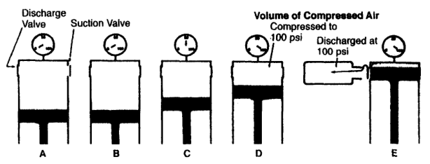
A reciprocating compressor traps a quantity of gas in a cylinder and reduces its volume with a piston.
The piston does not force gas continuously through an open passage. It repeatedly fills, closes, compresses, and discharges a separate volume of gas.
The compressor reference describes a reciprocating compressor as a piston, cylinder, and valve arrangement in which pressure rises as piston volume is reduced.
3. The four basic events
An ideal single-acting cycle contains four events:
- Suction or intake
- Compression
- Discharge
- Expansion or re-expansion of clearance gas
The order on an ideal indicator diagram is commonly represented as:
The cycle repeats every revolution for a single-acting cylinder. In a double-acting cylinder, an equivalent cycle occurs on both sides of the piston, displaced in crank angle.
4. Basic cylinder arrangement
A simple cylinder contains:
- Cylinder bore
- Piston
- Piston rod
- Suction valve
- Discharge valve
- Cylinder head
- Clearance space
- Suction passage
- Discharge passage
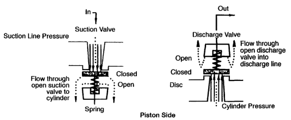
The suction and discharge valves are normally automatic pressure-activated valves. They open when the pressure difference across them is sufficient to overcome spring force, inertia, and flow resistance.
5. Event 1 — Suction stroke
During suction:
- The piston moves away from the cylinder head.
- Cylinder volume increases.
- Cylinder pressure falls below suction-line pressure.
- The suction valve opens.
- Gas flows into the cylinder.
- The discharge valve remains closed.
- Near the end of the stroke, piston deceleration allows the suction valve to close.
The valve does not open simply because the piston starts moving. It opens when cylinder pressure becomes sufficiently lower than suction pressure.
Suction pressure difference
This pressure difference drives gas into the cylinder.
Suction valve closing
The suction valve should close close to the end of the intake stroke. If it closes too early, the cylinder is underfilled. If it closes too late, gas may flow back into the suction passage during the beginning of compression.
6. Event 2 — Compression stroke
During compression:
- The piston reverses direction.
- The suction valve closes.
- The discharge valve remains closed.
- Cylinder volume decreases.
- Gas pressure rises.
- Gas temperature rises.
- The piston continues until cylinder pressure exceeds discharge-line pressure sufficiently to open the discharge valve.
The ideal compression path is often represented by:
where n depends on heat transfer and actual operating conditions.
For ideal adiabatic compression:
For ideal isothermal compression:
Actual compression usually lies between these ideal limits.
7. Event 3 — Discharge stroke
During discharge:
- Cylinder pressure rises slightly above discharge-line pressure.
- The discharge valve opens.
- The piston continues toward the cylinder head.
- Compressed gas is pushed into the discharge passage.
- Cylinder pressure approaches discharge pressure.
- Near the end of the stroke, piston speed reduces.
- The discharge valve closes as pressure equalises and flow reverses tendency.
The discharge valve requires an opening pressure above the line pressure because it must overcome:
- Spring force
- Valve-plate inertia
- Static pressure equalisation
- Flow resistance
- Pulsation effects
The compressor reference states that cylinder pressure must exceed discharge-line pressure by a small amount before the discharge valve opens.
8. Event 4 — Clearance-gas re-expansion
At the end of discharge, a small quantity of gas remains trapped in the cylinder and valve pockets.
This gas is at approximately discharge pressure.
When the piston reverses:
- The discharge valve closes.
- Trapped high-pressure gas expands.
- Cylinder pressure falls.
- The suction valve remains closed while cylinder pressure is above suction pressure.
- The suction valve opens only after cylinder pressure falls slightly below suction-line pressure.
This is the re-expansion portion of the cycle.
The re-expansion stroke does not draw fresh gas into the cylinder. It uses part of the piston travel to expand gas already inside the cylinder.
9. The ideal p-V diagram
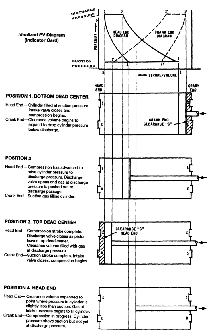
An ideal p-V diagram plots:
- Vertical axis: pressure
- Horizontal axis: cylinder volume
The four ideal processes are:
The enclosed area represents ideal compression work, subject to the sign convention used in the diagram.
10. Position 1 — Start of compression
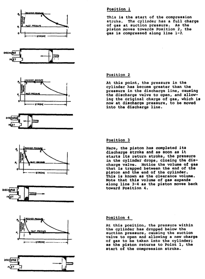
At position 1:
- The piston is at the beginning of its compression stroke.
- The cylinder contains a charge of gas at suction pressure.
- The suction valve has closed.
- The discharge valve is closed.
- Compression begins as the piston reduces volume.
The pressure starts rising along the compression curve.
If the suction valve closes late, the cylinder may still communicate with the suction line while the piston begins moving, reducing effective compression and causing reverse flow.
11. Position 2 — Discharge-valve opening
At position 2:
- Cylinder volume has decreased.
- Cylinder pressure has risen above discharge-line pressure.
- The discharge valve opens.
- Gas begins entering the discharge passage.
The pressure must be slightly above line pressure because a real valve has opening resistance.
The pressure difference needed to open a valve depends on:
- Spring characteristics
- Valve mass
- Valve lift
- Gas flow rate
- Pulsation
- Valve-seat condition
- Pressure equalisation
A high opening difference indicates increased valve loss or a mechanical problem.
12. Position 3 — End of discharge
At position 3:
- The piston is near top dead centre.
- Most of the deliverable gas has left the cylinder.
- Gas remains in the clearance volume.
- The discharge valve closes.
- The trapped gas is at high pressure.
The piston cannot remove all gas because physical clearance is necessary to prevent contact between piston and cylinder head and to accommodate thermal expansion and manufacturing tolerances.
13. Position 4 — Suction-valve opening
At position 4:
- The piston has started its return stroke.
- Clearance gas has expanded.
- Cylinder pressure has fallen below suction-line pressure.
- The suction valve opens.
- Fresh gas begins filling the cylinder.
The volume between position 4 and position 1 is the effective intake volume.
It is smaller than the full swept volume because some piston travel was consumed by clearance-gas expansion.
14. Dead-centre positions
Top dead centre
At top dead centre:
- Piston velocity is momentarily zero.
- Piston reverses direction.
- Clearance volume is minimum.
- Cylinder may contain high-pressure trapped gas.
- Valve timing changes from discharge to re-expansion.
Bottom dead centre
At bottom dead centre:
- Piston velocity is momentarily zero.
- Piston reverses from suction to compression.
- The suction valve should close.
- The cylinder contains its fresh charge.
Dead-centre positions are not necessarily the exact valve-opening positions because pressure equalisation, valve inertia, and flow dynamics affect timing.
15. Single-acting and double-acting operation
Single-acting compressor
Compression occurs on one side of the piston only.
Double-acting compressor
Compression occurs on both sides of the piston.
The two sides have separate suction and discharge valves. The piston rod passes through a packing arrangement at the crank end.
In a double-acting cylinder, one side may be compressing while the other side is filling. This provides more capacity for a given frame and speed but adds packing, valve, and rod-load considerations.
The compressor reference distinguishes single-acting operation, where compression occurs on one side, from double-acting operation, where it occurs on both sides.
16. Cycle timing in a double-acting cylinder
A double-acting cylinder has two overlapping cycles:
| Head end | Crank end |
|---|---|
| Compression | Suction |
| Discharge | Compression |
| Re-expansion | Discharge |
| Suction | Re-expansion |
The crank-end cycle is approximately 180° out of phase with the head-end cycle, subject to actual valve timing and geometry.
This arrangement smooths the delivery compared with a single-acting cylinder but does not eliminate pulsation.
17. Automatic valve operation
Automatic compressor valves are pressure-actuated.
They are not normally opened by a cam or external mechanical linkage.
Suction valve
Opens when:
Closes when the pressure difference reverses or spring force closes the valve as flow decelerates.
Discharge valve
Opens when:
Closes when pressure equalises and flow reversal or spring force returns the valve to its seat.
The small pressure differences needed for operation are called valve losses when they contribute to the actual compression work.
18. Real valve motion
A real valve does not open and close instantaneously.
During opening:
- The valve plate accelerates.
- Flow area increases.
- Pressure drop changes.
- Gas velocity changes.
During closing:
- Gas velocity decreases.
- Spring force becomes dominant.
- The valve plate returns to its seat.
- Pulsation may cause bounce or delayed closure.
Poor valve dynamics can cause:
- High pressure loss
- Reduced capacity
- Higher temperature
- Valve impact
- Valve fatigue
- Reverse flow
- High power consumption
19. Valve pressure losses
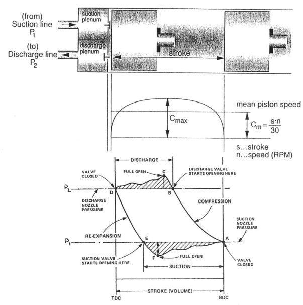
The ideal p-V diagram assumes valves open at line pressures and have no flow restriction.
A real indicator card includes:
- Suction pressure loss
- Discharge pressure loss
- Valve-opening delay
- Valve-closing delay
- Port restriction
- Gas pulsation
The actual suction line may lie below the suction-line pressure because gas must accelerate through the valve.
The actual discharge line may lie above discharge-line pressure because gas must flow through the discharge valve and port.
These losses enlarge the work area.
20. Piston displacement
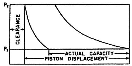
Piston displacement is the geometric volume swept by the piston per unit time at rated speed.
For a single-acting cylinder:
For a double-acting cylinder, both head-end and crank-end swept volumes are included, with the crank-end volume reduced by piston-rod area.
A simplified double-acting relationship is:
where:
- A = effective piston area
- L = stroke length
- N = cycles per unit time
The exact unit conversion depends on whether dimensions are in metres, millimetres, inches, cubic metres per minute, or cubic feet per minute.
The appendix gives piston-displacement relationships for single- and double-acting cylinders.
21. Piston displacement versus actual capacity
Piston displacement is not the same as actual delivered air.
Actual capacity is reduced by:
- Clearance volume
- Valve pressure losses
- Leakage past piston rings
- Leakage through valves
- Heating of suction gas
- Flow restrictions
- Unloading devices
- Pulsation
Therefore:
where:
- Q_actual = actual inlet-volume capacity
- PD = piston displacement
- η_v = volumetric efficiency
A compressor can have a large geometric displacement but deliver less air than expected if its cycle is inefficient.
22. Clearance volume
Clearance volume is the volume remaining between the piston and cylinder head at the end of the stroke, including valve-pocket and passage volume.
Clearance is required for:
- Mechanical safety
- Thermal expansion
- Manufacturing tolerance
- Valve installation
- Piston deflection
- Operating alignment
Clearance cannot be reduced to zero in a practical machine.
Typical normal clearance varies by design and cylinder type. The indexed reference gives a broad range of approximately 4–16% for many standard cylinders.
23. Clearance and capacity loss
At the end of discharge, clearance gas remains at high pressure.
During the return stroke, this gas must expand before the suction valve can open.
Increasing clearance causes:
- Longer re-expansion
- Later suction-valve opening
- Smaller effective intake stroke
- Lower volumetric efficiency
- Lower actual capacity
24. Clearance and compression ratio
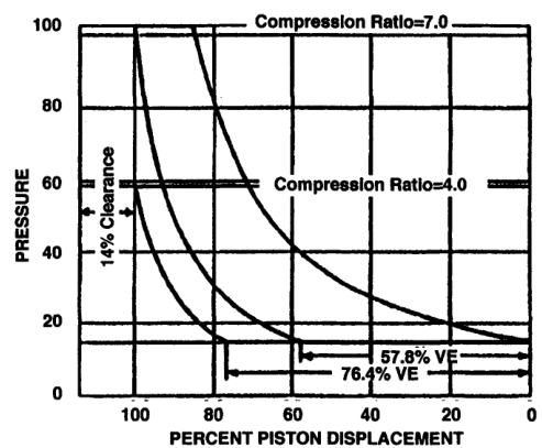
The effect of clearance becomes worse as compression ratio increases.
Compression ratio:
At a higher ratio:
- Clearance gas reaches a higher pressure.
- More expansion is required before suction begins.
- Effective intake volume decreases.
- Volumetric efficiency falls.
This is why high-ratio single-stage compressors can lose capacity rapidly.
25. Clearance does not automatically increase power
For a compressor designed for a specified capacity and operating condition, normal clearance primarily reduces capacity.
If the compressor must still deliver the same mass flow, it may need:
- Higher speed
- Larger cylinder
- More cylinders
- Longer operating time
- Different operating point
Those changes may increase power in the complete system.
The normal geometric clearance itself is not automatically equivalent to a separate power load at fixed design capacity; its principal direct effect is reduced fresh-gas intake.
26. Compression ratio is a system condition
Compression ratio is not controlled only by the compressor.
It depends on:
- Suction pressure
- Discharge pressure
- Receiver pressure
- System restrictions
- Filter condition
- Cooler pressure drop
- Atmospheric pressure
For example, at sea level, 100 psig discharge is approximately:
With suction at 14.7 psia:
The compressor reference uses this type of calculation for air service.
27. Compression work
The area enclosed by the actual indicator card represents work done by the compressor cylinder, with valve and flow losses included.
For an ideal polytropic process:
For actual machines, the measured indicated work is affected by:
- Compression path
- Valve losses
- Clearance
- Gas leakage
- Cylinder cooling
- Pressure pulsation
- Gas properties
The larger the pressure-area loop, the greater the indicated work for the same amount of gas.
28. Actual indicator card
An actual indicator card differs from the ideal card.
Typical features:
- Suction line below suction pressure
- Compression curve rounded by heat transfer
- Discharge opening above line pressure
- Discharge line above system pressure
- Pressure pulsations
- Delayed valve closure
- Uneven re-expansion
- Ring leakage
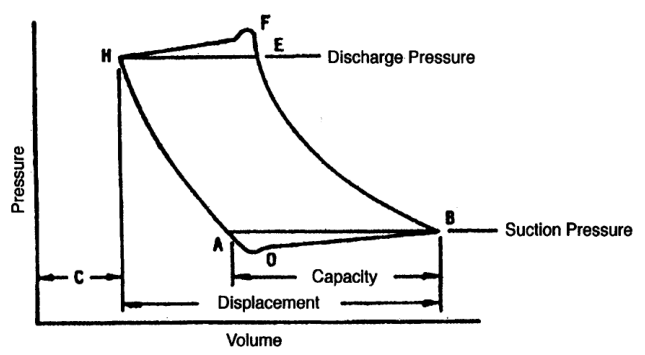
The card can be used to estimate indicated power and identify abnormal cylinder behaviour.
29. Ideal cycle versus actual cycle
| Feature | Ideal cycle | Actual cycle |
|---|---|---|
| Valve opening | Exactly at line pressure | Requires pressure difference |
| Valve closing | Instantaneous | Delayed and dynamic |
| Flow path | No restriction | Pressure losses |
| Gas leakage | None | Possible through rings and valves |
| Pressure lines | Smooth and constant | Pulsating and distorted |
| Compression | Ideal PV^n path | Heat transfer and losses |
| Clearance | Accounted for ideally | Geometric and valve-pocket volume |
| Work | Theoretical | Higher indicated work |
30. Suction-valve fault symptoms
A leaking or restricted suction valve can cause:
- Low suction filling
- Reduced capacity
- High suction-side pressure loss
- Higher cylinder temperature
- Abnormal p-V card
- Possible reverse flow during compression
- Increased power per unit of delivered gas
If a suction valve does not close properly, compressed gas can flow back toward the suction line.
If it opens late, the effective suction stroke is shortened.
If its spring is too stiff, a larger pressure difference is needed to open it.
31. Discharge-valve fault symptoms
A leaking or restricted discharge valve can cause:
- High discharge temperature
- Low delivered capacity
- High cylinder pressure late in the stroke
- Reverse flow during re-expansion
- Valve-cover heating
- Excessive pressure loss
- Abnormal p-V card
If the discharge valve opens late, the piston must compress above line pressure for longer.
If it fails to seat, high-pressure gas returns to the cylinder during the next suction or compression event.
32. Piston-ring leakage
Piston rings seal the moving piston against the cylinder wall.
Ring leakage allows gas to pass from the high-pressure side toward the low-pressure side.
Effects:
- Lower capacity
- Higher cylinder temperature
- Reduced compression efficiency
- Pressure loss during compression
- Possible contamination of crankcase in lubricated machines
- Increased oil carryover risk
Ring leakage often produces a distorted compression path rather than a clean valve-opening fault.
33. Clearance fault versus valve fault
Excessive clearance
Expected pattern:
- Longer re-expansion
- Later suction opening
- Reduced effective intake volume
- Lower volumetric efficiency
- Pressure curve may otherwise appear smooth
Suction-valve fault
Expected pattern:
- Abnormal suction pressure loss
- Delayed opening or poor closing
- Possible reverse flow
- Irregular suction line
Discharge-valve fault
Expected pattern:
- Delayed discharge opening
- High pressure before opening
- High discharge temperature
- Possible pressure pulsations
Diagnosis requires pressure, temperature, capacity, and card evidence together.
34. Cylinder pressure and crank angle
A cylinder-pressure trace plotted against crank angle can show valve timing.
Typical sequence:
The exact angles depend on design and valve dynamics.
Pressure and vibration traces can be used together to identify valve opening and closing behaviour.
35. Gas pulsation
Gas does not flow steadily from a reciprocating compressor.
Each piston stroke produces a pressure pulse.
Pulsation can cause:
- Valve chatter
- Delayed valve closing
- Pipe vibration
- Gauge fluctuation
- Unequal cylinder loading
- Resonance
- Fatigue in piping supports
Pulsation dampers and correctly designed piping reduce these effects but do not change the fundamental four-event cycle.
36. Suction and discharge valve design implications
Suction and discharge valves experience different conditions.
Suction valve
- Lower pressure differential during opening
- Inlet gas may be cool
- Must admit gas with low pressure drop
- Must close reliably before compression
Discharge valve
- Higher gas temperature
- Larger pressure differential
- Higher impact and flow loading
- Greater risk of deposits
- Must close before re-expansion
Valve design must account for pressure, temperature, speed, gas composition, lubrication, and pulsation.
37. Cycle interpretation: low capacity
If capacity is low, work through the cycle in order:
- Is suction pressure available?
- Is the suction filter restricted?
- Does the suction valve open fully?
- Does it close at the correct point?
- Is clearance excessive?
- Is compression pressure rising normally?
- Does the discharge valve open?
- Is discharge pressure too high?
- Are piston rings leaking?
- Is the compressor unloaded or bypassing?
Do not immediately replace a valve without checking system pressure and unloading controls.
38. Cycle interpretation: high temperature
High discharge temperature may result from:
- High compression ratio
- Restricted suction
- Restricted discharge
- Leaking discharge valve
- Poor cooling
- High intake temperature
- Ring leakage
- Excessive valve pressure loss
- Wrong gas composition
- Liquid or deposit damage
Compare the affected cylinder with the other cylinders.
A single abnormal cylinder suggests a local valve, ring, clearance, or cooling fault. All cylinders being hot suggests a system or cooling condition.
39. Cycle interpretation: knocking
Possible causes of cylinder knocking include:
- Loose piston
- Insufficient end clearance
- Excessive piston-to-bore clearance
- Broken piston ring
- Loose rider band
- Loose or broken valve
- Moisture carryover
- Liquid slugging
Liquid cannot be compressed like gas. A liquid slug can generate severe impact loads and break valve seats or other components.
The indexed maintenance reference identifies liquid carryover and insufficient clearance among causes requiring investigation.
40. Liquid carryover and the cycle
Liquid entering the cylinder disrupts the normal gas cycle.
Instead of gas being compressed smoothly:
- Liquid occupies cylinder volume.
- Piston motion creates hydraulic impact.
- Valve plates may strike or break.
- Lubrication may be washed away.
- Rings may wear rapidly.
- Pressure pulses may become severe.
Drain separators, intercoolers, and low points before liquid can reach the cylinder.
41. Basic piston-displacement calculation
Problem
A single-acting cylinder has:
- Bore diameter = 100 mm
- Stroke = 120 mm
- Speed = 600 rpm
Find approximate geometric displacement per minute.
Solution
Piston area:
Swept volume per revolution:
At 600 rpm:
This is piston displacement, not guaranteed delivered capacity.
If volumetric efficiency is 80%:
42. Double-acting displacement concept
For a double-acting cylinder, both piston sides contribute.
However, the crank-end effective area is smaller because the piston rod occupies part of the cylinder area.
Approximate displacement:
The exact formula depends on the manufacturer’s convention and whether the stated displacement includes both ends.
Always confirm:
- Single or double acting
- Head-end area
- Crank-end area
- Rod diameter
- Stroke
- Rated speed
- Number of cylinders
43. Compression-ratio example
A compressor receives air at 1.0 bara and discharges at 8.8 bara.
If suction is 1 bara and discharge is quoted as 7.8 barg:
The ratio is therefore 8.8:1, not 7.8:1.
44. Why discharge pressure controls valve timing
If discharge pressure rises:
- Compression continues farther before discharge opens.
- Cylinder pressure remains high later in the stroke.
- Discharge work increases.
- Capacity may fall.
- Discharge temperature may rise.
- Frame and rod loading may increase.
If discharge pressure falls:
- Discharge opens earlier.
- The effective discharge stroke changes.
- The compressor may operate away from its design point.
System pressure is therefore part of the compressor cycle.
45. Why suction pressure controls capacity
If suction pressure falls:
- Gas density falls.
- Mass admitted per swept volume falls.
- Compression ratio rises.
- Volumetric efficiency may decrease.
- Capacity falls.
- Power per unit of delivered mass may increase.
Possible causes:
- Intake filter restriction
- Suction valve fault
- Low atmospheric pressure
- Suction pipe restriction
- Excessive intake temperature
46. Clearance, swept volume, and effective volume
Definitions:
- Swept volume: volume moved by the piston between dead centres.
- Clearance volume: volume remaining at the end of the compression stroke.
- Total cylinder volume: clearance volume plus swept volume.
- Effective suction volume: volume filled with fresh gas after clearance-gas re-expansion.
This distinction is central to volumetric efficiency.
47. Indicator-card work areas
An actual card can be divided conceptually into:
- Useful compression work
- Suction-valve loss
- Discharge-valve loss
- Port and passage loss
- Pulsation distortion
The compressor maintenance reference explains that the enclosed p-V area represents compression work and that valve and flow-resistance areas represent additional energy expenditure.
The card is therefore both:
- A thermodynamic work measurement.
- A diagnostic picture of valve and cylinder condition.
48. Ideal cycle drawing exercise
Draw the following from memory:
- Horizontal volume axis.
- Vertical pressure axis.
- Suction pressure line.
- Discharge pressure line.
- Compression curve 1–2.
- Discharge line 2–3.
- Re-expansion curve 3–4.
- Suction line 4–1.
- Clearance volume at position 3.
- Piston positions at each point.
Then add real-machine effects:
- Suction pressure loss.
- Discharge pressure loss.
- Delayed valve opening.
- Rounded compression path.
- Pressure pulsation.
49. Revision questions with answers
Question 1
What are the four basic events in a reciprocating-compressor cycle?
Answer: Suction, compression, discharge, and clearance-gas re-expansion.
Question 2
Why does the suction valve open?
Answer: Cylinder pressure falls sufficiently below suction-line pressure.
Question 3
Why does the discharge valve open?
Answer: Cylinder pressure rises sufficiently above discharge-line pressure.
Question 4
What is clearance volume?
Answer: The volume remaining between piston and cylinder head, including valve pockets and passages, at the end of the stroke.
Question 5
Why does clearance reduce capacity?
Answer: Trapped high-pressure gas must re-expand before fresh gas can enter.
Question 6
What is piston displacement?
Answer: The geometric volume swept by the piston per unit time.
Question 7
Is piston displacement equal to actual capacity?
Answer: No. Actual capacity is reduced by volumetric and flow losses.
Question 8
What is the compression ratio?
Answer: Absolute discharge pressure divided by absolute suction pressure.
Question 9
What does the area inside an indicator card represent?
Answer: Indicated compression work, including actual process and flow effects.
Question 10
What happens if a discharge valve opens late?
Answer: Cylinder pressure rises excessively before discharge, increasing work and temperature.
Question 11
What happens if a suction valve closes late?
Answer: Gas may flow back toward the suction side during early compression.
Question 12
What is the difference between single-acting and double-acting operation?
Answer: Single-acting compression occurs on one piston side; double-acting compression occurs on both sides.
Question 13
Why can liquid cause severe compressor damage?
Answer: Liquid is effectively incompressible and can create hydraulic impact and break valves or seats.
Question 14
Why must absolute pressure be used in compression ratio?
Answer: Thermodynamic pressure ratios require pressure measured from absolute zero.
Question 15
What does a high discharge temperature suggest?
Answer: Possible high ratio, poor cooling, valve leakage, restriction, ring leakage, or abnormal flow loss.
50. Self-test scenarios
Scenario A — low capacity with normal motor current
Possible causes:
- Excessive clearance
- Suction valve not opening fully
- Suction valve leaking
- Piston-ring leakage
- Unloader partly open
- Low suction pressure
Scenario B — high discharge temperature and high power
Possible causes:
- Discharge valve opening late
- Discharge passage restriction
- High receiver pressure
- Poor cooling
- Piston-ring leakage
- Wrong compression ratio
Scenario C — knocking during loaded operation
Check:
- Piston and rod clearances
- Valves and valve seats
- Clearance volume
- Piston rings
- Liquid carryover
- Rider bands
Scenario D — card shows low suction pressure
Check:
- Intake filter
- Suction valve
- Suction pipe
- Atmospheric pressure
- Suction temperature
- Gauge calibration
Scenario E — double-acting cylinder has one weak end
Compare head-end and crank-end:
- Valve condition
- Ring sealing
- Clearance
- Temperature
- Pressure trace
- Packing leakage
51. Cycle-monitoring watchkeeping checklist
At each round, check:
- Suction pressure
- Discharge pressure
- Suction temperature
- Discharge temperature
- Interstage pressure where fitted
- Valve-cover temperature
- Abnormal knocking
- Pulsation
- Condensate drain condition
- Lubricating-oil pressure
- Cooling-water flow
- Motor current
- Receiver pressure rise
- Unloader condition
- Leakage from packing and joints
Compare against the machine’s normal baseline.
52. Chapter-five study checklist
- ☐ Explain positive-displacement compression.
- ☐ Name the four cycle events.
- ☐ Explain the suction stroke.
- ☐ Explain the compression stroke.
- ☐ Explain the discharge stroke.
- ☐ Explain clearance-gas re-expansion.
- ☐ Draw an ideal p-V diagram.
- ☐ Label points 1, 2, 3, and 4.
- ☐ Relate each point to piston position.
- ☐ Define top and bottom dead centre.
- ☐ Explain automatic valve operation.
- ☐ Explain single-acting operation.
- ☐ Explain double-acting operation.
- ☐ Define piston displacement.
- ☐ Distinguish displacement from actual capacity.
- ☐ Explain clearance-volume loss.
- ☐ Calculate absolute compression ratio.
- ☐ Explain valve pressure losses.
- ☐ Identify suction-valve faults.
- ☐ Identify discharge-valve faults.
- ☐ Identify ring leakage symptoms.
- ☐ Explain liquid slugging risk.
- ☐ Interpret basic p-V symptoms.