
Volumetric Efficiency in Air Compressors Explained
Eighty-two out of a hundred: where the missing eighteen cubic metres went.
Key Principles at a Glance 7 points
- Volumetric efficiency is actual inlet capacity divided by piston displacement, so 82 m3/min delivered from 100 m3/min displacement is 82%.
- The ideal relationship is driven by clearance and compression ratio: 8% clearance at 1 bara suction and 10 bara discharge falls further when discharge rises to 12 bara.
- Clearance control is a capacity-control method in its own right, because adding clearance pockets reduces delivery without stopping the machine.
- Bumping clearance is measured and not assumed, because clearance grows with wear and directly costs capacity.
- A fall in capacity of a few percent can be normal clearance loss, but the same loss from valve slip or ring leakage is a fault, and the two must be separated before any repair.
- Suction temperature and altitude cut volumetric efficiency by reducing air density, which is why a compressor delivers less on a hot day or at height.
- Volumetric efficiency is not compression efficiency and not mechanical efficiency, because each measures a different part of the power flow.
1. Learning objectives
Course position: Air-compressor sequence, Topic 6
Level: Reciprocating-compressor performance and diagnosis
Main question: Why does a compressor deliver less gas than its geometric piston displacement, and how can clearance, pressure ratio, valves, rings, temperature, and speed change actual capacity?
After studying this chapter, you should be able to:
- Define piston displacement.
- Define volumetric efficiency.
- Distinguish geometric displacement from actual inlet capacity.
- Explain clearance volume and clearance-gas re-expansion.
- Calculate basic volumetric efficiency.
- Explain the effect of compression ratio.
- Explain the effect of clearance percentage.
- Explain valve slip and pressure loss.
- Explain piston-ring leakage.
- Explain suction temperature and suction-pressure effects.
- Explain clearance pockets used for capacity control.
- Diagnose low capacity using volumetric-efficiency evidence.
- Explain why multistaging affects capacity.
- Apply volumetric-efficiency calculations to practical compressor operation.
2. Why piston displacement is not delivered capacity
A reciprocating compressor has a defined geometric swept volume. If the piston has a bore, stroke, and speed, the swept volume can be calculated.
However, the cylinder does not fill its entire swept volume with fresh gas at suction conditions during every cycle.
Capacity is reduced by:
- Clearance-gas re-expansion
- Suction-valve pressure loss
- Discharge-valve pressure loss
- Valve slip
- Piston-ring leakage
- High suction temperature
- Low suction pressure
- Restricted intake passages
- Unloaders and clearance pockets
- Pulsation
- Gas-property changes
Therefore:
where:
- Q_actual = actual capacity at stated inlet conditions
- PD = piston displacement
- η_v = volumetric efficiency
The compressor reference states that volumetric efficiency must be applied to piston displacement to determine actual free-air capacity.
3. Definition of piston displacement
Piston displacement is the geometric volume swept by the piston per unit time at rated speed.
For a single-acting cylinder:
For a double-acting cylinder, both ends contribute, but the crank-end area is reduced by piston-rod area.
Piston displacement depends on:
- Cylinder bore
- Piston-rod diameter
- Stroke length
- Speed
- Number of cylinders
- Single- or double-acting arrangement
Piston displacement does not by itself indicate how much gas reaches the receiver.
4. Definition of volumetric efficiency
Volumetric efficiency is the ratio of actual fresh gas drawn into the cylinder to piston displacement.
If a cylinder has:
- Piston displacement = 100 m³/min
- Actual inlet capacity = 82 m³/min
then:
The missing 18% is not necessarily one single fault. It may include theoretical clearance loss and practical valve, leakage, temperature, and flow losses.
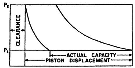
5. The effective suction stroke
The piston travels through its complete stroke, but fresh gas enters only after clearance gas has expanded below suction pressure.
The distance from suction-valve opening to the end of the suction stroke is the effective intake stroke.
The compressor reference represents volumetric efficiency on the p-V diagram as the effective suction distance divided by total piston stroke.
6. Clearance volume
Clearance volume is the volume remaining when the piston is at the end of its compression stroke.
It includes:
- Space between piston and cylinder head
- Valve pockets
- Valve passages
- Port volume
- Manufacturing allowance
- Thermal-expansion allowance
Clearance is necessary because a piston must not strike the cylinder head or valves during operation.
It cannot normally be eliminated, although good design keeps it as small as practical.
7. Clearance percentage
Percent clearance is defined as:
where:
- V_c = clearance volume
- V_s = piston displacement or swept volume
If clearance volume is 15 cm³ and swept volume is 100 cm³:
The calculation appendix defines percent clearance as clearance volume divided by piston displacement.
8. Clearance-gas re-expansion
At the end of discharge, the clearance space contains gas near discharge pressure.
During the return stroke:
- The discharge valve closes.
- The piston moves away from the head.
- Clearance gas expands.
- Cylinder pressure falls.
- Suction remains closed while cylinder pressure exceeds suction pressure.
- Suction opens only when cylinder pressure falls below suction pressure.
The piston has already moved some distance before fresh gas enters.
That lost distance reduces volumetric efficiency.
9. Ideal volumetric-efficiency relationship
For an ideal compressor with clearance, the approximate relationship is:
where:
- C = clearance ratio as a decimal
- P₁ = suction absolute pressure
- P₂ = discharge absolute pressure
- n = re-expansion exponent
The same relationship may be written:
where:
This equation represents ideal clearance loss only. Actual volumetric efficiency is lower when valve losses, leakage, heating, and restrictions are present.
10. Clearance-loss example
Problem
A cylinder has:
- Clearance ratio C=0.10
- Compression ratio r=5
- Re-expansion exponent n=1.3
Estimate ideal volumetric efficiency.
Solution
Since:
then:
This is an ideal estimate before practical valve and leakage losses.
11. Effect of increasing clearance
Increasing clearance causes:
- More high-pressure gas to remain trapped.
- Longer re-expansion.
- Later suction-valve opening.
- Smaller effective intake volume.
- Lower volumetric efficiency.
- Lower actual capacity.
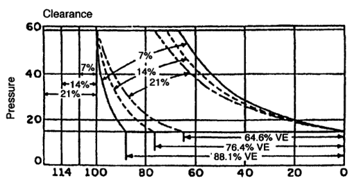
The indexed compressor text shows decreasing volumetric efficiency as clearance increases at constant compression ratio.
12. Effect of compression ratio
At higher compression ratio, clearance gas expands through a larger pressure range.
Higher ratio causes:
- Greater re-expansion volume
- Later suction opening
- Lower effective intake volume
- Lower volumetric efficiency
The important relationship is:
Not gauge pressure.
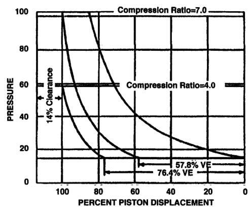
The compressor reference identifies both increasing clearance and increasing compression ratio as causes of falling volumetric efficiency.
13. Compression-ratio example
A compressor operates at:
- Suction = 1 bara
- Discharge = 10 bara
- Clearance ratio = 8%
The compression ratio is:
If discharge rises to 12 bara while suction remains 1 bara:
The clearance-gas expansion becomes greater and volumetric efficiency decreases.
This explains why actual capacity can fall when receiver pressure rises, even though piston speed remains constant.
14. Volumetric efficiency is not pressure efficiency
Volumetric efficiency measures how much fresh gas enters the cylinder.
It does not directly measure:
- Mechanical friction
- Indicated compression work
- Motor efficiency
- Driver losses
- Cooler losses
- Receiver leakage
Related efficiencies include:
Compression efficiency
Ratio of theoretical compression power to actual indicated power.
Mechanical efficiency
Ratio of indicated power to brake or shaft power.
Overall efficiency
A combined measure including gas compression, mechanical, electrical, and auxiliary losses.
Do not use the terms interchangeably.
15. Suction temperature effect
For a given suction pressure, hotter gas has lower density.
As suction temperature rises:
- Density falls.
- Mass admitted per swept volume falls.
- Actual mass capacity decreases.
- Compression ratio may be unchanged, but temperature margin worsens.
- Discharge temperature increases.
A volumetric-efficiency percentage may remain similar while mass delivery decreases because the inlet gas is less dense.
Therefore capacity reports must state inlet pressure and temperature.
16. Suction-pressure effect
If suction pressure falls:
- Gas density falls.
- Mass delivered per stroke falls.
- Compression ratio rises for the same discharge pressure.
- Clearance loss increases.
- Volumetric efficiency decreases.
- Power per unit of delivered mass may rise.
Causes include:
- Restricted intake filter
- Small suction pipe
- Closed or partly closed valve
- Low atmospheric pressure
- Suction-valve failure
- High inlet temperature
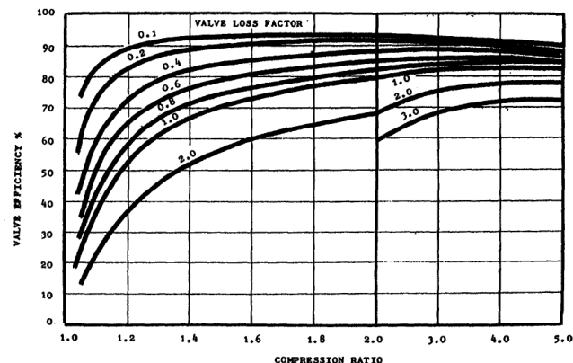
17. Valve pressure loss
A valve requires a pressure difference to open and maintain flow.
Suction-side loss
The cylinder pressure must fall below suction-line pressure to accelerate gas through the valve.
Discharge-side loss
Cylinder pressure must rise above discharge-line pressure to push gas through the valve.
Valve loss reduces effective capacity and increases work.
It can cause:
- Reduced volumetric efficiency
- Higher discharge temperature
- Higher indicated power
- Valve-cover heating
- Pressure pulsation
- Local valve damage
The compressor calculations appendix provides valve-loss and valve-efficiency relationships for estimating these effects.
18. Valve slip
Valve slip is reverse gas flow through a valve before it has fully seated.
Suction-valve slip
Hot compressed gas can flow back toward the suction side.
Effects:
- Reduces fresh-gas intake
- Heats incoming gas
- Raises suction temperature
- Reduces density
- Lowers volumetric efficiency
- May distort or overheat the valve
Discharge-valve slip
High-pressure discharge gas can return to the cylinder after the discharge stroke or during the next cycle.
Effects:
- Recompression of already compressed gas
- Lower net capacity
- Higher temperature
- Higher work
- Valve heating
The compressor reference identifies valve slip and reversed flow as capacity and power losses.
19. Piston-ring leakage
Piston-ring leakage allows gas to pass from the high-pressure side of the piston toward the lower-pressure side.
In a double-acting cylinder, leakage may enter the opposite end that is taking suction.
Effects:
- Reduces delivered capacity.
- Heats incoming gas.
- Raises cylinder temperature.
- Increases indicated power.
- Reduces compression efficiency.
- Can contaminate the crankcase or packing area.
Maximum leakage often occurs near the end of the stroke because pressure difference and time under high differential are greatest.
The indexed text states that piston-ring leakage produces both volumetric and horsepower losses and increases discharge temperature.
20. Piston-ring leakage diagnosis
Possible signs:
- Capacity slowly decreases.
- Discharge temperature rises.
- Crankcase pressure increases.
- Oil carryover changes.
- One cylinder is hotter than its counterpart.
- p-V compression line becomes abnormal.
- Blow-by sound or crankcase breathing increases.
Confirm with:
- Cylinder pressure comparison
- Temperature comparison
- Leakage measurement
- Crankcase-pressure measurement
- Ring inspection
- Capacity test at controlled pressure
Do not diagnose rings only from low receiver filling; intake restriction and valve faults can produce similar symptoms.
21. The practical volumetric-efficiency balance
Actual volumetric efficiency may be represented conceptually as:
This is a diagnostic model, not a universal manufacturer equation.
A small loss in several areas can produce a large total reduction.
For example:
- Clearance loss: 0.82
- Valve condition: 0.96
- Ring sealing: 0.97
- Flow restriction: 0.95
Approximate combined effect:
The cylinder may deliver only about 72% of piston displacement under those combined conditions.
22. Volumetric-efficiency calculation from capacity
Problem
A compressor has piston displacement of 120 m³/min and actual inlet capacity of 90 m³/min.
Solution
If the capacity is stated at standard conditions while piston displacement is stated at actual suction conditions, convert both to a common basis before calculating.
23. Capacity basis matters
Capacity may be quoted as:
- ACFM: actual cubic feet per minute at inlet conditions
- ICFM: intake cubic feet per minute
- SCFM: standard cubic feet per minute
- Free-air delivery
- Mass flow in kg/s
- Normal m³/min
Volumetric efficiency compares actual cylinder intake volume with geometric swept volume. ACFM and ICFM are generally closer to that basis than SCFM.
Always record:
- Pressure basis
- Temperature basis
- Humidity basis
- Mass or volume basis
- Location of measurement
24. Capacity versus discharge pressure
At constant speed and suction condition, increasing discharge pressure usually reduces delivered capacity because:
- Compression ratio increases.
- Clearance gas expands more.
- Suction begins later.
- Valve pressure losses increase.
- Leakage may increase.
- Gas temperature rises.
This is why a compressor may deliver substantially less air at 100 psi than at 50 psi with the same piston displacement.
The compressor reference states that capacity varies widely with pressure conditions because gas is elastic.
25. Capacity versus speed
Increasing speed can increase geometric displacement:
But actual capacity may not increase proportionally because:
- Valve response becomes more difficult.
- Flow losses increase.
- Pulsation increases.
- Heating increases.
- Ring leakage time and dynamics change.
- Driver power may become limiting.
A speed increase must remain within:
- Mean piston-speed limit
- Valve-speed limit
- Lubrication limit
- Cooling limit
- Vibration limit
- Driver limit
26. Capacity control by adding clearance
A clearance pocket adds extra volume connected to the cylinder.
Opening the pocket:
- Increases clearance volume.
- Increases re-expansion.
- Delays suction opening.
- Reduces fresh-gas intake.
- Reduces compressor capacity.
Closing the pocket reverses the effect.
This method allows capacity reduction without changing speed.
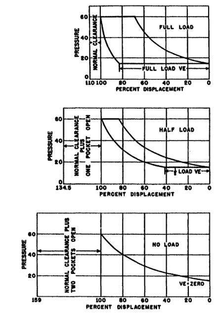
The compressor reference describes fixed-volume and pneumatically actuated clearance pockets used to reduce capacity in steps.
27. Why clearance control can save energy
When system demand is low, reducing capacity may be better than forcing the compressor to produce excess air and repeatedly unload or cycle.
Clearance control can:
- Match capacity to demand.
- Reduce receiver overpressure cycling.
- Avoid excessive throttling or blow-off.
- Prevent driver overload at changed pressure.
However, capacity-control settings alter cylinder re-expansion and should be included in performance calculations.
28. Clearance control and driver protection
Extra clearance may be used:
- To reduce capacity at fixed pressure.
- To prevent driver overload when operating pressure changes.
If compression ratio rises, the compressor may demand more power while delivering less capacity. Opening a clearance pocket reduces the amount of fresh gas compressed per cycle and can limit power.
This is a control function, not a repair for poor normal clearance.
29. Clearance measurement
Clearance may be established by:
- Manufacturer dimensions
- Mechanical measurement during overhaul
- Lead-wire or soft-metal bumping measurement
- Piston-position measurement
- Indicator-card interpretation
- Calculation from cylinder geometry
Measurement must be performed carefully to avoid:
- Bending the piston rod
- Contact damage
- Incorrect dead-centre reference
- Foreign material remaining in the cylinder
- Unsafe barring operation
The Samant notes describe bumping-clearance measurement using soft lead material and adjustment using shims.
30. Bumping clearance
Bumping clearance is the minimum safe distance between piston and cylinder head or other fixed components at the end of the stroke.
It must account for:
- Thermal expansion
- Rod stretch
- Bearing clearance
- Frame deflection
- Piston movement
- Manufacturing tolerance
- Operating alignment
Too little clearance risks mechanical contact.
Too much clearance reduces volumetric efficiency.
The correct value is a safety and performance compromise.
31. Wear and increasing clearance
Wear can increase clearance through:
- Piston wear
- Rider-band wear
- Bearing wear
- Crosshead wear
- Loose cylinder head or gasket changes
- Rod alignment changes
- Worn shims
Effects:
- Lower volumetric efficiency
- Lower capacity
- Changed indicator-card shape
- Possible knocking if alignment is poor
- Changed compression ratio behaviour
Clearance should be checked against the manufacturer’s limits during overhaul.
32. Multistage compressor volumetric efficiency
In a multistage compressor:
- The low-pressure cylinder admits the initial gas volume.
- The high-pressure cylinder handles denser interstage gas.
- The low-pressure stage largely determines total machine capacity.
- A fault in the low-pressure stage starves following stages.
- A fault in a high-pressure stage causes interstage pressure to rise.
The compressor reference notes that the low-pressure cylinder largely determines overall volumetric performance because gas delivered to later stages must first pass through it.
33. Stage-specific efficiency
Each stage has its own volumetric efficiency:
The stages must pass approximately the same mass flow, but not the same volume flow.
If the first stage loses capacity:
- Interstage pressure falls.
- High-pressure stage is starved.
- Final capacity falls.
If the second stage loses capacity:
- Interstage pressure rises.
- First-stage discharge becomes restricted.
- First-stage temperature and work may rise.
34. Temperature and density correction
For ideal gas:
If suction temperature rises from 300 K to 330 K at constant pressure:
Density falls by approximately 9.1%.
Even if volumetric efficiency is unchanged, mass capacity falls by approximately the same proportion.
This is why capacity data without inlet temperature are incomplete.
35. Altitude effect
At altitude:
- Atmospheric pressure is lower.
- Suction absolute pressure decreases.
- Air density decreases.
- Compression ratio to the same discharge pressure increases.
- Mass capacity falls.
- Volumetric efficiency may fall because ratio rises.
- Compressor may require derating or a larger low-pressure cylinder.
The compressor reference notes that low atmospheric pressure at altitude reduces intake pressure and can require cylinder-size changes or derating.
36. Valve condition and capacity
Valve problems reduce volumetric efficiency through:
- Delayed opening
- Incomplete lift
- Excessive spring force
- Broken plates
- Deposits
- Poor seating
- Valve chatter
- Reverse flow
- Damaged seats
A valve may appear to move but still have excessive pressure loss.
Measure or compare:
- Valve-cover temperature
- Pressure drop
- Capacity
- Cylinder pressure trace
- Discharge temperature
- Vibration
37. Valve losses and gas velocity
Higher gas velocity through a valve generally increases pressure loss.
Velocity rises when:
- Compressor speed increases.
- Valve area is restricted.
- Gas density is low.
- Flow passage is fouled.
- Valve lift is insufficient.
Pressure loss contributes to additional indicated work and can reduce effective capacity.
The compressor calculation reference relates valve losses to gas molecular weight and velocity.
38. Cooling and volumetric performance
Cylinder cooling can reduce gas temperature during compression.
Benefits include:
- Lower compression temperature
- Lower specific volume during the cycle
- Lower work
- Better lubrication
- Lower valve temperature
- Reduced deposit formation
Cooling does not remove clearance volume, but it can influence the compression path and actual capacity.
Poor cooling may raise suction-side and cylinder temperatures, reduce density, and increase leakage.
39. Moisture and volumetric efficiency
Moist intake air contains water vapour.
During compression and cooling:
- Vapour may condense.
- Liquid can restrict valves.
- Liquid can wash lubricant away.
- Deposits or corrosion can reduce valve performance.
- Liquid slugging can damage the cylinder.
Condensate management protects the volumetric efficiency that the cylinder geometry was designed to provide.
40. Low-capacity diagnostic sequence
When capacity is low:
Step 1 — Confirm the measurement
Check pressure, temperature, flow-meter basis, and receiver leakage.
Step 2 — Confirm operating point
Record suction pressure, discharge pressure, speed, and load state.
Step 3 — Calculate compression ratio
Use absolute pressures.
Step 4 — Check inlet restriction
Inspect filter, suction valve, pipe, and silencer.
Step 5 — Check clearance
Review design value, capacity-control pockets, and bumping clearance.
Step 6 — Compare valve temperatures
An abnormal valve may indicate leakage or restriction.
Step 7 — Check ring leakage
Compare cylinder temperature, crankcase pressure, and card shape.
Step 8 — Check cooling and drains
Poor cooling or liquid carryover can damage valves and rings.
Step 9 — Check unloading
Verify that unloaders and clearance pockets are in the intended position.
41. Fault table
| Observation | Likely volumetric effect | Checks |
|---|---|---|
| Capacity low, ratio high | Clearance loss increased | Absolute suction/discharge pressure |
| Capacity low, suction pressure low | Reduced density and higher ratio | Filter, pipe, valve |
| High suction-valve temperature | Valve slip or restriction | Valve plate, spring, seat |
| High discharge-valve temperature | Discharge slip or late opening | Discharge valve, port, deposits |
| Capacity slowly declining | Ring or valve wear | Leakage, temperatures, card |
| Capacity low after overhaul | Excessive bumping clearance | Clearance measurement |
| Capacity changes with control signal | Clearance pocket/unloader | Control position and actuator |
| One stage weak | Local valve/ring fault | Stage pressure and temperature |
| All cylinders weak | System condition | Pressure, speed, inlet temperature |
| High power and low capacity | Leakage or valve loss | Indicator card and valve inspection |
42. Worked capacity example
Problem
A compressor has piston displacement of 150 m³/min. Its ideal clearance-based volumetric efficiency is 82%. Practical valve and leakage losses reduce performance by a further 8% relative to the ideal value. Find approximate actual capacity.
Solution
Ideal capacity:
Practical capacity factor:
The estimated actual capacity is approximately 113 m³/min at the stated inlet basis.
43. Worked clearance comparison
Case A
- C=0.08
- r=4
- n=1.3
Case B
- C=0.14
- r=4
- n=1.3
Since the compression ratio is the same, Case B has greater clearance loss and lower volumetric efficiency.
The difference is caused by the larger trapped high-pressure volume, not by a change in piston displacement.
44. Worked pressure-ratio comparison
A compressor has 10% clearance and n=1.3.
At ratio 4
At ratio 8
The second value is lower because the clearance gas expands through a larger ratio.
This explains why a compressor may lose capacity as final pressure rises even without mechanical deterioration.
45. Volumetric efficiency and demand
A compressor may fail to meet system demand because:
- Demand increased.
- Pressure set point increased.
- Suction condition worsened.
- Clearance pocket opened.
- Valve leakage developed.
- Ring leakage increased.
- Speed fell.
- Cooling deteriorated.
- Receiver or distribution leakage increased.
Do not assume every capacity problem is an internal compressor fault.
Separate:
- Compressor capacity.
- Receiver pressure rise.
- Distribution-system demand.
- Leakage downstream.
46. Capacity test method
A controlled capacity test should establish:
- Stable suction pressure
- Stable discharge pressure
- Stable speed
- Known inlet temperature
- Known gas composition
- Known humidity if relevant
- Known receiver volume
- Start and stop pressures
- Time interval
- Condensate condition
Compare measured capacity with the manufacturer’s guarantee at the same basis.
A result is not meaningful if the test uses a different pressure, temperature, or flow basis.
47. Volumetric efficiency versus motor power
A low volumetric efficiency may produce either lower or higher measured motor power depending on the fault.
Clearance increase
Usually reduces fresh-gas mass processed per cycle and may reduce total power at the same speed.
Valve leakage
Can require recompression of gas and increase power per delivered unit.
Ring leakage
Can increase temperature and indicated work while reducing capacity.
Therefore use both capacity and power:
A compressor with low capacity and normal power may have poor filling.
A compressor with low capacity and high power likely has leakage, valve loss, high ratio, or mechanical problems.
48. Volumetric efficiency and specific power
Specific power rises when:
- Delivered capacity falls.
- Compression ratio rises.
- Valve losses rise.
- Ring leakage rises.
- Cooling worsens.
- Mechanical friction rises.
Monitoring specific power is often more useful than motor current alone.
Motor current may remain within limit while efficiency deteriorates because the compressor is delivering less air for the same input.
49. Revision questions with answers
Question 1
What is volumetric efficiency?
Answer: Actual fresh-gas intake volume divided by piston displacement, expressed as a percentage.
Question 2
What is the capacity relationship?
Answer: Q_actual=PD×η_v.
Question 3
Why does clearance reduce capacity?
Answer: Clearance gas must re-expand before fresh gas can enter.
Question 4
What two major variables reduce ideal clearance-based volumetric efficiency?
Answer: Clearance ratio and compression ratio.
Question 5
Why must compression ratio use absolute pressure?
Answer: Thermodynamic ratios require absolute pressure.
Question 6
What is valve slip?
Answer: Reverse gas flow through a valve before it has fully seated.
Question 7
How does suction-valve slip affect capacity?
Answer: It returns hot gas to the suction side, reducing fresh-gas intake and density.
Question 8
How does ring leakage affect performance?
Answer: It lowers capacity, raises temperature, and increases volumetric and horsepower losses.
Question 9
What is a clearance pocket?
Answer: An added volume used to increase clearance and reduce cylinder capacity for control.
Question 10
Why does high suction temperature reduce mass capacity?
Answer: Gas density decreases as temperature rises at constant pressure.
Question 11
Why does altitude reduce capacity?
Answer: Atmospheric suction pressure and gas density decrease, while compression ratio to a fixed discharge pressure increases.
Question 12
Why might capacity fall while speed remains constant?
Answer: Pressure ratio, clearance, valve condition, leakage, suction temperature, restrictions, or unloading may have changed.
Question 13
What is piston displacement?
Answer: Geometric swept volume per unit time.
Question 14
Can piston displacement be used directly as delivered capacity?
Answer: No. Volumetric efficiency and inlet conditions must be applied.
Question 15
What is specific power?
Answer: Power input divided by delivered mass or volume flow at a stated basis.
50. Self-test scenarios
Scenario A — low flow and low power
Likely directions:
- Excessive clearance
- Unloader or clearance pocket open
- Low suction pressure
- Intake restriction
- Reduced gas density
Scenario B — low flow and high power
Likely directions:
- Discharge valve leakage
- Piston-ring leakage
- High discharge pressure
- Valve pressure loss
- Poor cooling
- Mechanical friction
Scenario C — capacity falls as receiver pressure rises
Likely explanation:
- Compression ratio increases.
- Clearance gas expands further.
- Volumetric efficiency decreases.
- Valve pressure losses may increase.
Scenario D — one cylinder has high temperature and low capacity
Check:
- Suction valve
- Discharge valve
- Piston rings
- Cylinder cooling
- Clearance
- Local pressure trace
Scenario E — capacity changes after overhaul
Check:
- Bumping clearance
- Valve assembly and springs
- Gaskets and port alignment
- Ring installation
- Cylinder-head seating
- Unloader position
- Instrument calibration
51. Watchkeeping checklist
Record:
- Suction pressure, absolute if possible
- Discharge pressure, absolute if possible
- Suction temperature
- Discharge temperature
- Speed
- Motor current
- Delivered capacity
- Receiver pressure-rise time
- Valve-cover temperatures
- Crankcase pressure
- Cooling-water flow and temperatures
- Unloader or clearance-pocket position
- Condensate-drain condition
- Abnormal noise or pulsation
Trend the data against the baseline rather than relying on one reading.
52. Chapter-six study checklist
- ☐ Define piston displacement.
- ☐ Define volumetric efficiency.
- ☐ State Q_actual=PDη_v.
- ☐ Define clearance volume.
- ☐ Define clearance percentage.
- ☐ Explain clearance-gas re-expansion.
- ☐ Explain the effective suction stroke.
- ☐ Use absolute pressure for compression ratio.
- ☐ Explain the ideal clearance formula.
- ☐ Calculate a basic efficiency.
- ☐ Explain pressure-ratio effect.
- ☐ Explain suction-temperature effect.
- ☐ Explain suction-pressure effect.
- ☐ Explain valve slip.
- ☐ Explain piston-ring leakage.
- ☐ Explain valve pressure loss.
- ☐ Explain clearance pockets.
- ☐ Explain bumping clearance.
- ☐ Explain altitude effect.
- ☐ Distinguish volumetric, compression, and mechanical efficiency.
- ☐ Diagnose low capacity from pressure, temperature, and power evidence.
- ☐ Calculate actual capacity from displacement and efficiency.