
Multistage Compression and Intercooling in Air Compressors
Sixteen to one in a single stage, or four to one twice: the same air, less work and cooler valves.
Key Principles at a Glance 8 points
- Equal pressure ratio per stage splits the work evenly: 1 bara to 16 bara becomes about 4:1 per stage in two stages, or about 2.52:1 in three.
- A rise from 1 bara to 25 bara is 5:1 per stage in two stages, giving an ideal interstage pressure of 5 bara.
- Intercooling lowers the temperature entering the next stage, which reduces the work of that stage and approaches isothermal compression.
- Two-stage compression to 100 psig saves roughly 10 to 15% power compared with single-stage compression under the same conditions.
- Heavy-duty water-cooled machines are commonly two-stage for 100 psig air service above about 125 bhp.
- Intercooler pressure drop is real: first-stage discharge at 5.2 bara and second-stage suction at 5.0 bara means 0.2 bara lost in the cooler and piping.
- A stage must not be judged on discharge pressure alone, because interstage pressure shows whether the stages are sharing the work correctly.
- Adding stages is not automatically better, because each extra stage adds valves, coolers, piping and maintenance points.
1. Learning objectives
Course position: Air-compressor sequence, Topic 4
Level: Applied thermodynamics and machine selection
Main question: Why is compression divided into stages, and how do stage ratio, intercooling, temperature, power, and pressure balance affect compressor operation?
After studying this chapter, you should be able to:
- Define single-stage and multistage compression.
- Explain why high pressure is divided between stages.
- Calculate overall and per-stage pressure ratio.
- Explain perfect and imperfect intercooling.
- Compare single-stage, two-stage, and three-stage compression.
- Explain stage temperature and pressure limitations.
- Explain how staging saves power.
- Explain the relation between stage ratio and cylinder size.
- Explain interstage pressure as a condition-monitoring signal.
- Diagnose low and high interstage pressure.
- Explain the effect of unequal stage efficiency.
- Explain why more stages are not always better.
- Describe single- and multistage arrangements in marine compressors.
- Answer calculations and examination questions on multistage compression.
2. What is a compression stage?
A compression stage is one complete pressure-raising step performed by a compressor cylinder or group of cylinders operating between a defined suction pressure and discharge pressure.
Single-stage compressor
The gas is compressed from initial suction pressure to final discharge pressure in one step.
Multistage compressor
The total pressure increase is divided into two or more stages.
The compressor reference defines multistage compression as completing compression in two or more distinct steps.
3. Why not compress everything in one stage?
A single stage becomes unsuitable when the required pressure ratio causes:
- Excessive discharge temperature
- Excessive power requirement
- Poor volumetric efficiency
- Excessive valve loading
- High piston and ring temperature
- Lubricant breakdown
- Carbon deposits
- High frame and rod loads
- Excessive pressure difference across the piston
- Unsafe discharge-pipe conditions
The compressor reference identifies discharge pressure, pressure rise, compression ratio, clearance, and power saving as major design limitations.
4. Main purposes of multistaging
The indexed compressor reference gives three primary reasons:
- Save power.
- Limit gas discharge temperature.
- Limit pressure differential and mechanical strain.
Additional benefits include:
- Improved volumetric efficiency
- Better control of cylinder size
- Condensate removal between stages
- Lower valve temperatures
- Better lubrication conditions
- More manageable frame loading
- Improved high-pressure reliability
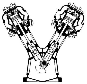
5. Two-stage compressor arrangement
A typical two-stage compressor contains:
- Low-pressure cylinder
- First-stage suction valve
- First-stage discharge valve
- Intercooler
- Interstage separator and drain
- High-pressure cylinder
- Second-stage suction valve
- Second-stage discharge valve
- Aftercooler
- Final separator
- Receiver
6. Three-stage compressor arrangement
A three-stage compressor divides the total ratio further:
Three stages may be selected when:
- Final pressure is high.
- One or two stages would produce excessive temperature.
- Rod load or frame load must be limited.
- The service requires a controlled pressure ratio per cylinder.
More stages add:
- Valves
- Coolers
- Separators
- Piping
- Pressure losses
- Maintenance points
- Cost
- Mechanical complexity
7. Overall pressure ratio
The overall pressure ratio is:
All pressures must be absolute.
Example
Suction pressure = 1 bara
Final discharge pressure = 16 bara
A single-stage compressor would experience the complete 16:1 ratio.
A two-stage compressor can divide it into approximately 4:1 per stage.
A three-stage compressor can divide it into approximately 2.52:1 per stage.
8. Equal pressure ratio per stage
For approximately equal stage ratios:
where:
- n = number of stages
Two stages
Three stages
Four stages
The compressor calculations appendix gives the general equal-stage-ratio relationship.
Equal ratios are a useful starting point, not a guarantee of actual operating pressure.
9. Two-stage pressure-ratio example
Problem
A compressor receives air at 1 bara and discharges at 25 bara. Estimate equal stage ratios for two stages.
Solution
Approximate intermediate pressure:
The idealised arrangement is:
Actual pressure may differ because of intercooler pressure drop and stage efficiency.
10. Three-stage pressure-ratio example
Problem
A compressor receives air at 1 bara and discharges at 64 bara. Estimate equal pressure ratio per stage.
Solution
Approximate pressures:
Each stage has a ratio of approximately 4:1.
11. Intermediate pressure
For equal stage ratios and negligible pressure losses:
Two-stage compressor
or:
where:
- P₁ = suction absolute pressure
- P₂ = intermediate absolute pressure
- P₃ = final discharge absolute pressure
Example
For P₁ = 1 bara and P₃ = 25 bara:
Pressure must be measured at a clearly defined point because intercooler pressure drop means the first-stage discharge pressure and second-stage suction pressure may not be identical.
12. What intercooling does
Intercooling removes heat from air between stages.
Intercooling:
- Reduces gas temperature.
- Increases gas density before the next stage.
- Reduces the work of the next stage.
- Reduces final discharge temperature.
- Protects valves and lubricant.
- Allows condensate to be separated.
- Reduces thermal stress.
Perfect intercooling returns the gas to approximately the original suction temperature between stages.
Actual intercooling is limited by:
- Cooling-water temperature
- Cooler surface area
- Fouling
- Flow rate
- Pressure drop
- Approach temperature
- Condensate drainage
13. Isothermal, adiabatic, and staged compression
A single-stage adiabatic process follows a hotter compression path than an isothermal process.
With intercooling, each stage compresses over a smaller ratio and returns the gas toward a lower temperature before the next stage.
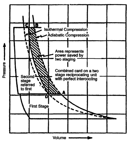
The area between the ideal adiabatic and staged/intercooled paths represents theoretical work saved.
14. Why intercooling saves power
During compression, the gas temperature rises.
If the gas remains hot before the next stage:
- Its specific volume remains high.
- The next stage must handle a larger volume.
- More work is required.
- Final temperature rises further.
If the gas is cooled:
- Specific volume decreases.
- The next-stage cylinder admits denser gas.
- Compression work decreases.
- The total cycle approaches the isothermal reference.
The cooling does not remove the need for compression work; it reduces the work required for the remaining compression.
15. Power-saving relationship
For a given final pressure ratio, multistage compression with effective intercooling requires less theoretical work than equivalent single-stage adiabatic compression.
The actual saving depends on:
- Overall pressure ratio
- Number of stages
- Intercooler effectiveness
- Valve efficiency
- Mechanical efficiency
- Gas properties
- Load factor
- Cooler pressure drop
- Leakage
The compressor reference notes that two-stage compression can produce significant power savings for common air-service pressures.
Do not quote a universal percentage without specifying the compressor and operating conditions.
16. Discharge temperature limitation
Compression temperature is a major reason for staging.
High temperature causes:
- Less effective lubrication
- Deposits on valves
- Shorter valve life
- Higher cylinder maintenance cost
- Carbon formation
- Fire risk in discharge piping
- Thermal distortion
- Higher oil evaporation
The cooling reference identifies these effects and notes that lower gas temperatures improve efficiency and reduce power.
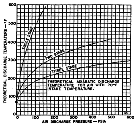
Two- and three-stage compression reduce the peak temperature per stage compared with a single-stage machine at the same final pressure.
17. Pressure differential limitation
Pressure differential across a cylinder creates gas forces on:
- Piston
- Piston rod
- Crosshead
- Connecting rod
- Crankshaft
- Bearings
- Frame
- Cylinder head
High pressure differential can produce:
- High rod loads
- Frame stress
- Bearing loading
- Vibration
- Distortion
- Reduced service life
Staging divides the pressure rise and helps keep each cylinder within its mechanical load limit.
18. Stage cylinder sizes
In a two-stage compressor, the high-pressure cylinder is normally smaller than the low-pressure cylinder.
Why?
After the first-stage compression and cooling, the air has a higher pressure and smaller specific volume.
Therefore, the high-pressure stage needs less swept volume to process the same mass flow.
This is not an arbitrary size difference. It follows from gas density and mass conservation.
19. Mass continuity between stages
At steady operation, the mass flow through all stages is approximately equal:
Volume flow is not equal because density changes.
As pressure increases and temperature is controlled:
- Density increases.
- Volumetric flow decreases.
- High-pressure cylinder can be smaller.
A leak or valve fault in one stage changes the effective mass flow and disturbs interstage pressure.
20. Intercooler pressure drop
An intercooler must remove heat without creating excessive pressure loss.
Pressure loss sources:
- Tube friction
- Fouling
- Small passages
- Condensate accumulation
- Restricted valves
- Blocked separators
- Poor piping
If first-stage discharge is 5.2 bara and second-stage suction is 5.0 bara:
A growing pressure drop may indicate fouling or condensate restriction.
21. Interstage pressure as a health indicator
Interstage pressure is one of the best simple indicators of multistage compressor condition.
Low interstage pressure
May indicate a problem in the preceding stage:
- First-stage suction valve leaking
- First-stage discharge valve not delivering
- First-stage piston-ring leakage
- First-stage suction restriction
- First-stage cylinder problem
High interstage pressure
May indicate a problem in the succeeding stage:
- Second-stage suction valve restricted
- Second-stage suction valve broken
- Second-stage piston-ring leakage
- Second-stage capacity loss
- Interstage pipe restriction
The compressor troubleshooting guidance uses interstage pressure to identify the faulty cylinder or stage.
22. Interstage pressure and load condition
A pressure reading must be interpreted with the compressor load state.
Record whether the compressor is:
- Unloaded
- Partially loaded
- Fully loaded
- Starting
- Stopping
- Operating against a rising receiver pressure
A low interstage pressure under load that remains normal when unloaded may point to a suction-valve problem in the preceding stage.
A sudden drop toward zero can indicate a serious discharge-valve failure.
23. Equal work per stage
Well-balanced multistage compressors are designed so that each stage performs approximately equal work.
For a two-stage 100-hp compressor, a rough balanced condition may involve approximately 50 hp per stage, although actual indicated and brake power distribution depends on design and losses.
Unequal work causes:
- Unequal temperature
- Unequal valve loading
- Wrong interstage pressure
- Mechanical overload in one stage
- Reduced total efficiency
The troubleshooting reference states that multistage compressors are designed for approximately equal work per stage and that improper ratios can cause rod-load, capacity, and vibration problems.
24. Stage-ratio calculation
For n stages:
Example: four-stage system
Overall pressure ratio = 81.
Ideal pressure sequence from 1 bara:
Actual pressure sequence includes pressure loss and different stage performance.
25. Why more stages are not always better
Adding stages can reduce theoretical compression work, but each additional stage introduces:
- Valve losses
- Piping losses
- Cooler pressure drop
- Mechanical friction
- More components
- More maintenance
- More condensate separators
- Greater capital cost
- More control complexity
The compressor reference notes that after several stages, additional power savings can become small because friction and pressure losses increase.
The optimum number of stages balances:
- Pressure ratio
- Capacity
- Temperature limit
- Power
- Mechanical load
- Cost
- Maintenance
- Reliability
26. Single-stage compressor: advantages
Advantages:
- Simple layout
- Fewer valves
- Fewer coolers
- Lower initial cost
- Easier maintenance
- Compact for moderate pressure ratios
- Simple control
Limitations:
- Higher discharge temperature
- Higher power for high ratios
- Lower volumetric efficiency at high ratio
- Greater piston and valve loading
- More difficult high-pressure operation
Single-stage compression is suitable when pressure ratio and discharge temperature remain within the design envelope.
27. Multistage compressor: advantages
Advantages:
- Lower total work
- Lower maximum gas temperature
- Better high-pressure operation
- Better volumetric efficiency
- Lower pressure difference per stage
- Condensate removal between stages
- Lower thermal and mechanical stress
Limitations:
- More equipment
- Higher cost
- More valves and coolers
- Interstage pressure-drop risk
- More complicated maintenance
- More opportunities for control and drainage faults
28. Compressor cooling systems
Cooling may be provided by:
- Air-cooled cylinder fins
- Water-cooled cylinder jackets
- Water-cooled intercoolers
- Water-cooled aftercoolers
- Separate closed cooling circuits
- Sea-water heat exchangers through a fresh-water loop
Water cooling provides:
- Lower gas temperature
- Better lubrication
- Lower friction
- Longer valve life
- Lower power
- Higher possible single-stage pressure within limits
The compressor reference gives water-jacket cooling benefits and warns that fouled cooling systems increase temperature.
29. Perfect and imperfect intercooling
Perfect intercooling
Gas leaves the intercooler at the original suction temperature.
This is a theoretical assumption used to calculate ideal work saving.
Imperfect intercooling
Gas leaves the intercooler above the original suction temperature.
Causes:
- Warm cooling water
- Fouled tubes
- Insufficient flow
- Limited surface area
- High gas flow
- Poor air-side heat transfer
The higher the interstage suction temperature, the higher the second-stage work and final discharge temperature.
30. Intercooler condensation
As hot compressed gas is cooled:
- Water vapour may reach saturation.
- Liquid water forms.
- A separator collects the liquid.
- A drain removes it.
If the drain fails:
- Liquid level rises.
- Gas passage may be restricted.
- Liquid may carry over to the next suction valve.
- Valve damage may occur.
Interstage drains are therefore part of the compression process, not a minor accessory.
31. Aftercooling
The final-stage discharge is hot.
An aftercooler reduces temperature before the air enters:
- Receiver
- Main air line
- Starting-air system
- Control-air dryer
- Pneumatic equipment
Benefits:
- Lower receiver temperature
- More condensate removal
- Less thermal stress in piping
- Better air quality
- Safer storage
Aftercooler pressure drop should be monitored.
32. Stage balance and cylinder condition
Stage balance changes when component condition changes.
First-stage valve leakage
- Low interstage pressure
- Lower mass delivered to the next stage
- Reduced final capacity
- Possible temperature changes
Second-stage suction restriction
- High interstage pressure
- First stage continues pushing gas into restricted space
- Higher first-stage discharge pressure
- Possible high temperature
Piston-ring blow-by
- Lower stage delivery
- Pressure leakage
- Higher temperature
- Lower capacity
- Unequal stage work
Cooler restriction
- High upstream pressure
- Low downstream pressure
- Increased temperature
- Possible liquid carryover
33. Multistage pressure troubleshooting table
| Symptom | Likely area | First checks |
|---|---|---|
| Low interstage pressure | Preceding stage | Suction/discharge valves, rings, suction filter |
| High interstage pressure | Succeeding stage | HP suction valve, cooler, interstage pipe |
| High final temperature | Cooling or stage ratio | Cooling flow, valve leakage, pressure ratio |
| Low final capacity | LP or HP stage | Valve condition, rings, unloaders |
| High power | Pressure or mechanical load | Stage pressure, cooler drop, bearings |
| Condensate carryover | Separator/drain | Drain operation, liquid level |
| Vibration | Unequal stage load | Interstage pressure, valves, foundation |
| Repeated valve failure | Temperature/liquid | Cooling, condensate, deposits |
34. Multistage pressure monitoring
A daily log should include:
- First-stage suction pressure
- First-stage discharge pressure
- Intercooler inlet pressure
- Intercooler outlet pressure
- Second-stage suction pressure
- Final discharge pressure
- Stage discharge temperatures
- Intercooler cooling-water temperature
- Aftercooler outlet temperature
- Condensate-drain condition
- Motor current
- Vibration
Trend changes rather than single readings.
The compressor reference recommends frequent observation of interstage pressures and treating deviation from normal as a reason for investigation.
35. Pressure-ratio example with intercooler loss
Problem
A two-stage compressor has:
- Suction = 1.0 bara
- Final discharge = 25 bara
- First-stage discharge before intercooler = 5.2 bara
- Second-stage suction after intercooler = 5.0 bara
Find:
- Overall ratio.
- First-stage ratio.
- Second-stage ratio.
- Intercooler pressure drop.
Solution
Overall:
First stage:
Second stage:
Intercooler pressure drop:
The stage ratios are close but not exactly equal because of intercooler pressure loss.
36. Temperature-limitation example
Problem
Why might a designer choose a two-stage compressor rather than a single-stage compressor for a 100-psig air system?
Answer
A two-stage arrangement can:
- Reduce peak discharge temperature.
- Save power through intercooling.
- Reduce pressure differential in each cylinder.
- Reduce deposits on valves.
- Improve lubrication.
- Reduce thermal stress.
- Improve service life.
The exact selection depends on capacity, duty cycle, cooling, and design pressure.
37. Power-saving concept example
Suppose a single-stage process compresses air from 1 bara to 16 bara without cooling between compression steps.
A two-stage compressor divides the ratio approximately:
Cooling after the first stage returns the gas closer to the initial temperature.
The second stage therefore compresses denser, cooler gas than it would receive from a hot single-stage process.
The result is lower total theoretical work and lower final temperature.
38. Why pressure ratio must use absolute pressure
A stage-ratio calculation using gauge pressure gives incorrect results.
Incorrect:
Correct, assuming 1 bar atmospheric pressure:
- Final = 21 bara
- Intermediate = 6 bara
Always use absolute pressure for stage ratio.
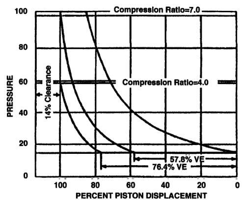
39. Multistage compression and volumetric efficiency
Volumetric efficiency is strongly affected by compression ratio and clearance.
As compression ratio increases:
- Clearance gas expands further.
- Suction valve opens later.
- Fresh intake volume decreases.
- Volumetric efficiency falls.
By dividing the total ratio into stages, each stage can operate at a lower ratio and maintain better volumetric performance.
The compressor reference notes that multistaging has a marked effect on volumetric efficiency, with the low-pressure cylinder influencing the complete machine.
40. Stage sizing and volumetric efficiency
The low-pressure cylinder handles the largest volume because suction gas has the lowest density.
The high-pressure cylinder handles a smaller volume because interstage gas is denser.
If the low-pressure stage loses capacity:
- The entire compressor capacity falls.
- The high-pressure stage may be starved.
- Interstage pressure may fall.
If the high-pressure stage loses capacity:
- Interstage pressure rises.
- The low-pressure stage may continue delivering into a restricted stage.
- Final discharge capacity falls.
41. Multistage refrigeration comparison
Refrigeration systems also use multistage compression when pressure ratio is high or discharge temperature is unacceptable.
The refrigeration text describes multistage cycles where gas from the first stage is cooled before entering the high-stage compressor.
The same principles apply:
- Divide pressure ratio.
- Cool between stages.
- Reduce volumetric-efficiency loss.
- Limit discharge temperature.
The working fluid and system arrangement differ from atmospheric-air compressors.
42. Why two or three stages are common
For many marine and industrial services, two or three stages provide a practical compromise.
Two stages:
- Good for moderate-to-high pressure.
- Reasonable equipment complexity.
- Manageable cooler and separator system.
Three stages:
- Better for higher final pressure.
- Lower ratio per cylinder.
- Lower peak temperature.
- More complex cooling and control.
The Samant notes summarise the practical idea that two or three stages are commonly feasible, with intercooling and power saving.
43. When single-stage may be preferred
Single-stage compression may be selected when:
- Final pressure is modest.
- Capacity is small.
- Duty is intermittent.
- Simplicity is valuable.
- Cooling is adequate.
- Discharge temperature is acceptable.
- Valve and cylinder loading remain within limits.
Do not select multistaging solely because it is theoretically more efficient. Compare lifecycle cost and duty.
44. When multistaging is required
Multistaging becomes attractive or necessary when:
- Pressure ratio is high.
- Single-stage discharge temperature is too high.
- Volumetric efficiency becomes unacceptable.
- Cylinder force exceeds the frame or rod limit.
- Power consumption is excessive.
- High-pressure air must be stored safely.
- Condensate removal between stages is beneficial.
45. Maintenance implications of multistaging
A multistage compressor has more maintenance points:
- More suction valves
- More discharge valves
- More cylinder covers
- More coolers
- More separators
- More drains
- More pressure instruments
- More temperature instruments
- More interstage piping
Maintenance priorities:
- Keep coolers clean.
- Keep separators drained.
- Monitor interstage pressure.
- Compare stage temperatures.
- Inspect valves equally.
- Check for unequal stage loading.
- Verify pressure instruments.
46. Safety implications of multistaging
Multistage systems contain multiple pressure zones.
Before maintenance:
- Isolate each stage.
- Vent all intercoolers.
- Drain condensate.
- Confirm zero pressure on both sides of valves.
- Check non-return valves.
- Lock out the driver.
- Prevent automatic restart.
A system may show zero final-discharge pressure while an intercooler or cylinder remains pressurised.
47. Why interstage pressure deviations matter
The cylinder sizes are designed for expected inlet pressure, final pressure, temperature, and cooling conditions.
If these change:
- Interstage pressure changes.
- Stage work becomes unequal.
- Temperature changes.
- Rod loads change.
- Vibration may increase.
- Capacity may fall.
The compressor reference states that design-condition changes and cooling-water temperature changes alter interstage pressure.
48. Stage-balance fault scenario
Observation
- First-stage discharge pressure is high.
- Second-stage suction pressure is high.
- Final pressure is low.
- Second-stage discharge temperature is low.
Likely direction
The second stage may not be accepting or compressing enough gas.
Check:
- Second-stage suction valve
- Second-stage unloader
- Second-stage piston rings
- Interstage passage
- Discharge valve
- Pressure gauge
49. Opposite stage-balance fault scenario
Observation
- Interstage pressure is low.
- First-stage discharge temperature is abnormal.
- Final capacity is low.
- Second-stage suction is starved.
Likely direction
The first stage may not deliver enough gas.
Check:
- First-stage suction valve
- First-stage discharge valve
- Intake filter
- Piston rings
- Cylinder leakage
- First-stage pressure instrument
50. Stage selection and lifecycle cost
The best number of stages depends on:
- Initial purchase cost
- Motor size
- Operating hours
- Electricity or fuel cost
- Cooling-water cost
- Maintenance cost
- Spare parts
- Reliability
- Required availability
- Consequence of failure
The compressor reference emphasises that lifetime power cost can be many times the first purchase cost.
A slightly more expensive multistage compressor may be cheaper over its operating life if it saves power and reduces maintenance.
51. Revision questions with answers
Question 1
What is a compression stage?
Answer: One pressure-raising step between a defined suction and discharge pressure.
Question 2
Why is compression divided into stages?
Answer: To save power, limit temperature, and limit pressure differential and mechanical loading.
Question 3
What is an intercooler?
Answer: A cooler that removes heat from gas between compression stages.
Question 4
What is the equal stage-ratio formula?
Answer: r_stage = (r_overall)^1/n.
Question 5
Why must stage ratios use absolute pressure?
Answer: Pressure ratios are thermodynamic ratios measured from a zero-pressure datum.
Question 6
Why is the high-pressure cylinder usually smaller?
Answer: Interstage gas is denser and occupies less volume for the same mass flow.
Question 7
What does low interstage pressure suggest?
Answer: A fault or restriction in the preceding stage, such as a suction/discharge valve or ring problem.
Question 8
What does high interstage pressure suggest?
Answer: A fault or restriction in the succeeding stage or interstage path.
Question 9
Why does intercooling save work?
Answer: It cools and densifies the gas before the next stage, reducing the work required.
Question 10
What is perfect intercooling?
Answer: Cooling the gas back to approximately the original suction temperature between stages.
Question 11
Why are too many stages undesirable?
Answer: Additional stages add friction, pressure loss, components, cost, and maintenance.
Question 12
What causes interstage pressure to change from design value?
Answer: Changes in suction pressure, final pressure, temperature, cooling, valve condition, leakage, or cooler pressure drop.
Question 13
What happens to condensate between stages?
Answer: It must be separated and drained to prevent liquid carryover.
Question 14
What is the main advantage of three stages over two at a high pressure ratio?
Answer: Lower ratio and temperature per stage, with lower mechanical and thermal loading.
Question 15
What determines the best number of stages?
Answer: Pressure ratio, capacity, temperature limit, power, mechanical load, cost, maintenance, and reliability.
52. Self-test scenarios
Scenario A — equal stage-ratio design
A compressor must raise pressure from 1 bara to 81 bara in four stages.
Calculate the approximate stage ratio:
Ideal pressure sequence:
Scenario B — low interstage pressure
Observed:
- First-stage suction normal
- Interstage pressure low
- Final discharge low
- Second stage appears starved
Investigate:
- First-stage suction valve.
- First-stage discharge valve.
- First-stage piston rings.
- Intake filter.
- Pressure instrument.
Scenario C — high interstage pressure
Observed:
- First-stage discharge high
- Interstage pressure high
- Final discharge low
- Second-stage temperature abnormal
Investigate:
- Second-stage suction valve.
- Interstage cooler and pipe restriction.
- Second-stage unloader.
- Second-stage piston rings.
- Second-stage discharge valve.
Scenario D — high discharge temperature
Check:
- Stage ratio
- Cooling-water flow
- Intercooler fouling
- Valve leakage
- Condensate drainage
- Lubrication
- Pressure instruments
Scenario E — deciding between one and two stages
A small intermittent machine needs modest pressure, has adequate cooling, and has low operating hours.
A single-stage machine may be reasonable.
A large continuous machine requires high pressure, low temperature, and low lifecycle power cost.
A multistage water-cooled machine is more likely to be appropriate.
53. Chapter-four study checklist
- ☐ Define a compression stage.
- ☐ Define single-stage compression.
- ☐ Define multistage compression.
- ☐ Explain the three primary reasons for multistaging.
- ☐ Draw a two-stage compressor system.
- ☐ Draw a three-stage compressor system.
- ☐ Calculate overall pressure ratio.
- ☐ Calculate equal stage ratio.
- ☐ Calculate approximate intermediate pressure.
- ☐ Explain perfect intercooling.
- ☐ Explain imperfect intercooling.
- ☐ Explain pressure drop through an intercooler.
- ☐ Explain condensate separation.
- ☐ Explain stage cylinder-size differences.
- ☐ Explain mass continuity between stages.
- ☐ Explain low interstage pressure.
- ☐ Explain high interstage pressure.
- ☐ Explain equal work per stage.
- ☐ Explain volumetric-efficiency improvement.
- ☐ Explain why too many stages are undesirable.
- ☐ Calculate a two-stage ratio.
- ☐ Calculate a three-stage ratio.
- ☐ Interpret a pressure-balance fault.
- ☐ Explain multistage safety isolation.