
Positive-Displacement and Dynamic Compressors Compared
Trapped and squeezed, or accelerated and diffused: two families and two failure modes.
Key Principles at a Glance 7 points
- Positive-displacement machines trap a fixed volume and raise its pressure, while dynamic machines accelerate a continuous flow and convert velocity into pressure.
- Positive-displacement types hold pressure almost independent of flow, whereas dynamic types trade pressure against flow and lose pressure as flow rises.
- Dynamic compressors have a surge and stall limit that positive-displacement machines do not, so their operating range is bounded on the low-flow side.
- Positive-displacement machines pulsate and are therefore fitted with receivers, pulsation bottles or dampers, while dynamic machines deliver a smoother flow.
- Reciprocating machines suit high pressure at low to medium flow, and centrifugal and axial machines suit high flow at moderate pressure ratio.
- Rotary screw, vane, lobe and scroll machines are all positive-displacement, so their capacity falls as wear opens internal leakage paths.
- Selection is driven by gas characteristics, load factor, cooling, space, weight, noise and maintenance capability, and the highest pressure rating on the datasheet rarely decides it.
1. Learning objectives
Course position: Air-compressor sequence, Topic 9
Level: Compressor families, operating characteristics, and preliminary selection
Main question: How do positive-displacement and dynamic compressors work, and which characteristics determine whether a reciprocating, rotary, centrifugal, or axial compressor suits a service?
After studying this chapter, you should be able to:
- Define positive-displacement compression.
- Define dynamic compression.
- Explain the difference between intermittent and continuous-flow compression.
- Classify reciprocating, rotary, centrifugal, axial, and ejector machines.
- Compare pressure, capacity, speed, pulsation, and control behaviour.
- Explain why reciprocating compressors suit high pressure and variable load.
- Explain why centrifugal compressors suit high flow.
- Explain axial-compressor applications and limitations.
- Explain rotary screw, vane, lobe, scroll, and liquid-piston principles.
- Explain surge, stall, slip, and clearance differences.
- Select a preliminary compressor family from process requirements.
- Include driver, foundation, cooling, space, maintenance, and lifecycle cost.
2. The two main compressor families
Industrial compressors are first divided into:
- Positive-displacement compressors
- Dynamic compressors
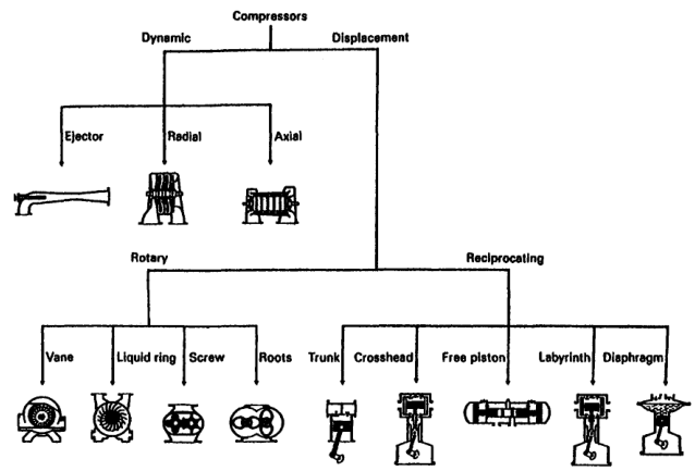
This is the first selection decision because the two families respond differently to flow, pressure, speed, system resistance, and load variation.
3. Positive-displacement compressors
A positive-displacement compressor traps successive quantities of gas in a closed or partially closed working space and raises pressure by reducing the available volume or by compressing gas within that space.
Examples:
- Reciprocating piston
- Rotary screw
- Sliding vane
- Rotary lobe
- Scroll
- Liquid piston
- Rolling piston
The basic sequence is:
The compressor reference describes positive-displacement machines as units in which successive gas volumes are confined and elevated to a higher pressure.
4. Dynamic compressors
A dynamic compressor continuously accelerates gas with a high-speed rotating element and converts velocity into pressure through diffusers, stationary blades, or flow passages.
Examples:
- Centrifugal or radial compressor
- Axial compressor
- Mixed-flow compressor
The basic sequence is:
The gas is not trapped in isolated piston pockets. Flow is continuous through the machine.
5. Other compression methods
The compressor reference describes four broad methods:
- Trap gas, reduce its volume, and discharge it.
- Trap gas, carry it to a discharge opening, compress it by backflow from the discharge system, and discharge it.
- Accelerate gas with rotating impellers or bladed rotors and convert velocity into pressure.
- Use a high-velocity jet to entrain gas and convert mixed-flow velocity into pressure in a diffuser.
The first two are positive-displacement methods. The third is dynamic compression. The fourth is ejector or jet compression.
6. Reciprocating piston compressors
A reciprocating compressor uses:
- Cylinder
- Piston
- Piston rod
- Suction valve
- Discharge valve
- Crankshaft
- Connecting rod
- Crosshead where fitted
Gas is drawn into the cylinder, compressed by piston movement, and discharged through automatic valves.
Characteristics:
- High pressure capability
- Good efficiency over a broad pressure range
- Strong part-load control
- Pulsating flow
- Reciprocating inertia forces
- More valves and wearing parts
- Larger foundation requirement than many rotary machines
The reciprocating machine is classified as a constant-volume, variable-pressure machine: displacement is set mainly by geometry and speed, while system pressure determines the pressure rise.
7. Rotary positive-displacement compressors
Rotary positive-displacement compressors trap and move gas using rotating elements.
They normally provide:
- Continuous or near-continuous flow
- Higher speed than reciprocating machines
- Lower pulsation than piston machines
- Compact packaging
- Fewer reciprocating inertia forces
They may be sensitive to:
- Internal clearances
- Oil condition
- Rotor timing
- Gas cleanliness
- Sealing
- Built-in pressure ratio
8. Rotary screw compressors
A screw compressor uses intermeshing helical rotors to trap and reduce gas volume as it moves along the rotor flutes.
Types include:
- Oil-injected twin screw
- Oil-free twin screw
- Single-screw design
Advantages:
- Continuous flow
- Low pulsation
- Compact package
- Good automatic capacity control
- Suitable for plant air and many process services
Limitations:
- Rotor and casing clearances are critical.
- Oil-injected types require separation and oil management.
- Oil-free types require precise rotor and sealing design.
- Built-in volume ratio must match operating pressure reasonably well.
The refrigeration reference notes that screw compressors have no conventional piston clearance volume and that their internal volume ratio is set by rotor geometry.
9. Sliding-vane compressors
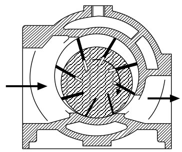
A sliding-vane compressor has a rotor mounted eccentrically in a casing. Radial vanes slide in rotor slots and form changing-volume pockets.
As the rotor turns:
- Pocket volume increases at suction.
- Gas enters the pocket.
- Pocket volume decreases.
- Gas is compressed.
- Gas leaves through the discharge port.
Advantages:
- Compact
- Smooth flow
- Simple rotary motion
- Suitable for moderate pressure and capacity
Limitations:
- Vane-tip wear
- Lubrication dependence
- Friction
- Sensitivity to liquid carryover
- Pressure limitation from vane loading
10. Rotary-lobe or Roots blowers
A lobe blower traps gas between rotating lobes and casing, then carries it from suction to discharge.
In a basic straight-lobe blower, there is little or no internal compression. Pressure rises mainly when the trapped gas meets the discharge-system pressure.
Characteristics:
- High flow
- Low-to-moderate pressure rise
- Simple rotors
- Pulsation requiring attention
- Useful for aeration, scavenging, and low-pressure air service
The compressor reference distinguishes straight-lobe machines from helical-lobe compressors and notes that straight-lobe gas is carried without internal compression.
11. Scroll compressors
A scroll compressor uses two spiral elements:
- One fixed scroll
- One orbiting scroll
Gas pockets form between the scrolls and move toward the centre while their volume decreases.
Advantages:
- Low vibration
- Few moving parts
- Compact and quiet operation
- Common in refrigeration and smaller air-conditioning systems
Limitations:
- Limited large-scale capacity range compared with centrifugal or reciprocating machines
- Sensitive to liquid carryover
- Often hermetic or semi-hermetic
- Repair may involve replacement rather than field overhaul
12. Liquid-piston compressors
A liquid-piston compressor uses liquid, often water, to form a moving sealing surface and reduce gas volume.
Advantages:
- Can tolerate some contaminants better than close-clearance dry machines
- Liquid can provide sealing and cooling
- Useful for selected process gases
Limitations:
- Liquid management
- Corrosion
- Carryover
- Pumping power
- Limited pressure ratio per stage
The compressor classification text identifies liquid-piston machines as rotary positive-displacement compressors using liquid as the piston.
13. Centrifugal compressors
A centrifugal compressor uses one or more rotating impellers.
Gas typically:
- Enters near the impeller eye.
- Accelerates radially outward.
- Gains velocity and kinetic energy.
- Passes through a diffuser or return passage.
- Converts velocity into static pressure.
Characteristics:
- Large continuous flow
- High rotational speed
- Low pulsation
- Compact flow path for large capacity
- Several stages may be used for higher pressure
- Performance strongly depends on flow and speed
The compressor reference defines centrifugal compressors as dynamic machines with radial gas flow through rotating impellers.
14. Axial compressors
An axial compressor uses alternating rows of rotating and stationary blades.
Gas flows mainly parallel to the shaft axis.
Each stage gives a relatively small pressure increase, so many stages are used for high overall pressure ratio.
Advantages:
- Very high flow capacity
- Compact frontal area for large flow
- Suitable for gas turbines and large air systems
Limitations:
- Narrow stable operating range
- Sensitive to fouling
- Sensitive to blade damage
- Stall and surge risk
- More difficult part-load operation
- High-speed rotating assembly
The compressor reference defines axial compressors by axial gas acceleration from bladed rotors.
15. Mixed-flow compressors
Mixed-flow compressors combine radial and axial flow characteristics.
They may provide a compromise between:
- Centrifugal flow capacity and pressure rise
- Axial compactness and flow direction
They are less common in basic marine air-compressor applications but appear in specialised turbomachinery and refrigeration systems.
16. Ejectors
An ejector uses a high-velocity motive jet to entrain another gas and convert mixed-stream velocity into pressure in a diffuser.
Characteristics:
- No conventional rotating shaft
- Uses motive steam or gas
- Suitable for vacuum or special process duties
- Low efficiency compared with many mechanical compressors
- Pressure ratio depends strongly on motive and suction conditions
Ejectors are not normally selected as the general-purpose source of compressed marine service air.
17. Positive displacement versus dynamic operation
| Feature | Positive displacement | Dynamic |
|---|---|---|
| Gas handling | Trapped volumes or pockets | Continuous flow |
| Pressure generation | Volume reduction or internal compression | Velocity converted to pressure |
| Flow response | Relatively strong pressure capability | Strongly dependent on flow and speed |
| Pulsation | Reciprocating types high; rotary types lower | Usually low |
| Capacity control | Speed, unloaders, clearance, bypass | Inlet guide vanes, throttling, speed, recycle |
| Pressure ratio | High for reciprocating; moderate for rotary | Several stages often needed |
| Part-load behaviour | Often good for reciprocating | May be limited by surge or stall |
| Flow range | Small to large | Medium to very large |
| Maintenance | Valves, rings, seals, rotors | Bearings, seals, blades, fouling |
| Foundation | Reciprocating needs dynamic support | Often mainly deadweight and alignment |
18. Constant-volume and variable-pressure behaviour
A positive-displacement compressor has a nearly fixed geometric displacement per revolution.
If discharge resistance increases:
- Pressure rises.
- Driver power rises.
- Capacity may fall due to clearance and leakage.
- Relief or control action may be required.
A dynamic compressor does not force a fixed volume into the discharge system in the same way. Its pressure and flow are determined by the compressor characteristic and system resistance.
19. Flow range
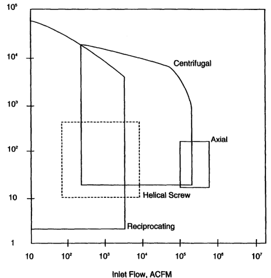
Flow rate is one of the most important selection variables.
Approximate tendencies:
- Reciprocating: low-to-high flow, especially strong at high pressure
- Rotary screw: medium flow, continuous plant air
- Rotary vane: low-to-medium flow, moderate pressure
- Roots blower: high flow, low pressure rise
- Centrifugal: high-to-very-high flow
- Axial: very-high flow
The indexed compressor reference provides approximate application ranges and notes that maximum values do not apply simultaneously to every service.
20. Pressure capability
Pressure capability depends on:
- Number of stages
- Pressure ratio per stage
- Cooling
- Material strength
- Sealing
- Valve or rotor design
- Gas temperature
- Lubrication
- Rod and frame load
Reciprocating compressors are often preferred for high pressure and lower flow.
Centrifugal compressors may be preferred for large flow and moderate pressure ratio, with multiple stages for higher pressure.
Axial compressors use many stages for large flow and moderate pressure rise per stage.
21. Speed comparison
Typical relative tendencies:
| Machine | Speed tendency |
|---|---|
| Heavy-duty reciprocating | Low to moderate |
| Small reciprocating | Moderate to high |
| Rotary screw | High |
| Rotary vane | Moderate to high |
| Centrifugal | Very high |
| Axial | Very high |
High speed reduces machine size but increases sensitivity to:
- Rotor balance
- Bearing condition
- Seal performance
- Blade condition
- Dynamic instability
- Lubrication
22. Pulsation comparison
Reciprocating compressors create discrete suction and discharge events, producing pulsation.
Rotary positive-displacement machines provide more continuous flow but may still produce rotor-passing pulsation.
Centrifugal and axial machines generally produce smoother flow, although aerodynamic disturbances and rotating stall can produce severe pressure fluctuations.
Pulsation matters because it affects:
- Piping vibration
- Valve life
- Foundation loading
- Flow-meter accuracy
- Noise
- Card interpretation
- System reliability
23. Surge and stall in dynamic compressors
Dynamic compressors require a stable relationship between flow and pressure rise.
Surge
A system-level instability in which flow oscillates or reverses because the compressor is operating below its stable flow range.
Stall
Local flow separation or blade aerodynamic failure that reduces pressure generation.
Possible results:
- Severe vibration
- Reversed flow
- High bearing loads
- Blade damage
- Driver instability
- Rapid temperature changes
Positive-displacement compressors do not experience aerodynamic surge in the same way, although they have their own pressure, pulsation, unloading, and valve-instability problems.
24. Slip and leakage in positive-displacement machines
Positive-displacement machines depend on sealing between working pockets and casing or rotor surfaces.
Leakage or slip increases when:
- Clearances grow
- Rotors wear
- Seals fail
- Gas viscosity changes
- Pressure ratio increases
- Temperature changes
Effects:
- Lower capacity
- Higher power per delivered unit
- Higher temperature
- Reduced pressure capability
Reciprocating machines use piston rings and valves; rotary machines depend on rotor clearances, seals, oil, or liquid sealing.
25. Reciprocating advantages
A reciprocating compressor is often attractive when:
- Pressure is high.
- Flow is moderate.
- Load varies widely.
- High efficiency is required.
- Several pressure stages are needed.
- Gas composition varies.
- Capacity control must be precise.
- Part-load efficiency matters.
- A positive-displacement characteristic is useful.
It can be configured as:
- Single- or double-acting
- Single- or multistage
- Air- or water-cooled
- Lubricated or non-lubricated
- Horizontal, vertical, V, Y, or opposed
- Single- or multicylinder
26. Reciprocating limitations
Limitations include:
- Pulsating flow
- Foundation and vibration requirements
- More valves and wearing parts
- Larger package for high flow
- Liquid intolerance
- Lubricant carryover risk
- More complicated maintenance
- Rod-load and frame-load limits
Clean, dry intake gas is important. Liquid carryover can damage valves and remove lubrication.
27. Rotary-screw advantages
Screw compressors are attractive when:
- Continuous flow is required.
- Flow is medium to high.
- Pressure is moderate.
- Low pulsation is desirable.
- Compact packaging matters.
- Automatic part-load control is required.
They are common for:
- Plant air
- Instrument air
- Workshop air
- Refrigeration
- Process gas
Oil-injected and oil-free designs have different air-quality and maintenance requirements.
28. Centrifugal advantages
Centrifugal compressors are attractive when:
- Flow is high.
- Flow is continuous.
- Pressure ratio per casing is moderate.
- Low pulsation is important.
- A turbine or high-speed driver is available.
- Foundation movement must be low.
The selection reference notes that centrifugal compressors deserve early consideration when the driver must be a turbine, while reciprocating compressors are often favourable with electric motors.
This is a selection tendency, not an absolute rule.
29. Axial advantages
Axial compressors are attractive when:
- Very high flow is required.
- Compact flow area is important.
- Several stages can be accommodated.
- The service resembles gas-turbine or large process-air duty.
They are less common for ordinary marine starting-air and instrument-air packages because those services usually favour reciprocating or rotary machines.
30. Driver compatibility
Driver selection affects compressor selection.
Consider:
- Electric motor speed
- Steam turbine speed
- Gas-engine speed
- Variable-speed drive capability
- Starting torque
- Power availability
- Exhaust or waste-heat integration
- Hazardous-area requirements
- Emergency operation
A compressor must match the driver’s speed, power, torque, control, and starting characteristics.
31. Foundation and vibration
Reciprocating machines generate inertia forces from:
- Piston acceleration
- Connecting rods
- Crankshaft rotation
- Gas pulsation
They may require:
- Rigid foundation
- Correct mass and stiffness
- Anchor bolts
- Pulsation bottles
- Flexible pipe connections
- Alignment control
Centrifugal machines generally have lower reciprocating inertia forces, but rotor balance and foundation stiffness remain essential.
The reference notes that centrifugal machines operate without reciprocating unbalanced forces, while reciprocating units require mounting that stabilises the installation.
32. Cooling requirements
Cooling selection depends on:
- Pressure ratio
- Gas flow
- Discharge temperature limit
- Ambient temperature
- Cooling-water availability
- Fouling environment
- Installation location
Reciprocating high-pressure machines commonly use cylinder jackets, intercoolers, and aftercoolers.
Rotary screw machines may use oil cooling and oil separators.
Centrifugal and axial machines use aerodynamic and bearing/seal cooling arrangements.
33. Lubrication and gas quality
Lubrication may be:
- Frame-only
- Cylinder lubricated
- Oil-injected
- Oil-free
- Liquid-sealed
Selection depends on whether oil contamination is acceptable.
Oil-free or labyrinth-piston machines may be selected for:
- Oxygen service
- Instrument air
- Chemical gas
- Food or pharmaceutical service
- Processes sensitive to oil contamination
Non-lubricated designs require careful attention to wear materials, clearances, heat, and sealing.
34. Marine-service examples
Starting air
Typical priorities:
- High pressure
- Reliable storage charging
- Good condensate separation
- High safety integrity
- Automatic start/stop
- Redundant or standby capacity
Reciprocating multistage compressors are common.
Instrument air
Typical priorities:
- Low oil carryover
- Dry air
- Reliable pressure
- Filtration and drying
- Stable automatic control
Oil-free reciprocating or oil-free screw designs may be selected.
Service or workshop air
Typical priorities:
- Moderate pressure
- Variable demand
- Low lifecycle cost
- Easy maintenance
- Good part-load control
Rotary screw or reciprocating machines may be suitable.
Large continuous process air
Typical priorities:
- Very high flow
- Continuous operation
- Low pulsation
- Turbine or high-speed driver compatibility
Centrifugal or axial machines may be appropriate.
35. Selection inputs
The compressor selection reference lists the following essential inputs:
- Required discharge pressure.
- Required capacity.
- Power supply characteristics.
- Cooling-water availability and cost.
- Space.
- Weight.
- Foundation type and size.
- Control type.
- Maintenance cost.
Also specify:
- Suction pressure range
- Suction temperature range
- Gas composition
- Humidity or liquid content
- Duty cycle
- Required availability
- Air-quality requirement
- Noise limit
- Hazardous-area classification
- Future capacity increase
36. Selection decision sequence
Do not start by choosing a familiar machine. Start with the duty.
37. Preliminary selection matrix
| Requirement | Likely family |
|---|---|
| Very high pressure, moderate flow | Reciprocating |
| Moderate pressure, continuous plant air | Rotary screw |
| Low-pressure, high-flow air | Lobe blower or centrifugal |
| Very high continuous flow | Centrifugal or axial |
| Wide part-load range | Reciprocating or well-controlled screw |
| Low pulsation | Screw or dynamic |
| Oil-free high-pressure gas | Oil-free reciprocating or specialised screw |
| Turbine driver | Centrifugal often considered early |
| Electric motor, high pressure | Reciprocating often considered early |
| Low vacuum or jet service | Ejector or specialised compressor |
This matrix is preliminary. Final selection requires manufacturer data.
38. Capacity-control comparison
Reciprocating
- Suction-valve unloaders
- Clearance pockets
- Start-stop
- Bypass
- Variable speed
- Cylinder cutout
Screw
- Slide valve
- Variable-speed drive
- Inlet modulation
- Stop-start
Centrifugal
- Inlet guide vanes
- Inlet throttling
- Speed control
- Recycle or blow-off
Axial
- Variable inlet guide vanes
- Variable stator vanes
- Speed control
- Bleed or bypass systems
The control method strongly affects part-load power and operating range.
39. Maintenance comparison
| Machine | Main maintenance focus |
|---|---|
| Reciprocating | Valves, rings, packing, lubrication, alignment |
| Screw | Oil, separator, rotor clearances, bearings, seals |
| Vane | Vanes, casing, lubrication, wear |
| Lobe | Timing gears, clearances, bearings, pulsation |
| Centrifugal | Bearings, seals, impellers, diffusers, fouling |
| Axial | Blades, bearings, clearances, fouling, stall/surge protection |
A machine with lower first cost may have higher maintenance or energy cost.
40. Lifecycle cost
Evaluate:
- Purchase cost
- Installation
- Foundation
- Piping and coolers
- Driver
- Electrical system
- Cooling system
- Lubricant and filters
- Spare parts
- Scheduled maintenance
- Unplanned downtime
- Energy consumption
- Operator workload
The compressor reference stresses that power cost over the service life may be many times the initial purchase cost.
41. Gas characteristics and selection
Gas properties influence selection:
- Molecular weight
- Specific heat ratio
- Compressibility
- Toxicity
- Flammability
- Corrosiveness
- Dew point
- Liquid content
- Lubricant compatibility
Low-density gas affects centrifugal compressors strongly because the machine may need more stages or a larger size to achieve the required pressure.
Positive-displacement machines may tolerate low-density gas differently, but capacity and sealing still change.
42. Liquid handling
Compressors generally prefer gas without entrained liquid.
Liquid can:
- Damage reciprocating valves
- Wash lubrication from cylinders
- Damage rotary clearances
- Cause screw separator problems
- Damage centrifugal blades
- Cause surge-like disturbances
Install and maintain:
- Suction separators
- Demisters
- Drains
- Interstage separators
- Aftercoolers
- Automatic or manual condensate systems
43. Load factor
Load factor is the actual compressed-gas output while operating divided by rated full-load output during the same period.
A plant designed to operate continuously at 100% rated output may have poor reliability margin.
The compressor reference suggests selecting installations for a practical load factor below full load, with the exact value depending on machine size, type, and number of units.
Benefits of suitable load factor:
- Pressure stability
- Cooling-off periods
- Standby margin
- Better maintenance planning
- Less continuous overload
44. Space and weight
Compare:
- Compressor package footprint
- Vertical clearance
- Receiver and cooler space
- Maintenance access
- Removal path for heavy components
- Foundation load
- Deck or platform strength
- Vibration transmission
- Ventilation
A compact machine that cannot be maintained safely is not a good selection.
45. Noise and vibration
Noise sources differ by machine:
- Reciprocating gas pulsation and impact
- Screw rotor meshing
- Lobe pressure pulses
- Centrifugal aerodynamic noise
- Axial blade noise
- Driver and bearing noise
Use:
- Pulsation bottles
- Acoustic enclosures
- Flexible connectors
- Proper supports
- Vibration monitoring
- Speed avoidance zones
Noise control must not create excessive suction or discharge restriction.
46. Selection example
Duty
A ship requires:
- Moderate flow
- High stored-air pressure
- Intermittent charging
- Reliable automatic operation
- Limited cooling-water availability
- High pressure and safety priority
Preliminary choice
A multistage reciprocating compressor is a strong candidate because it provides:
- High pressure capability
- Good intermittent-duty performance
- Effective capacity control
- Manageable flow at high pressure
- Intercooling and condensate removal
A rotary screw may be considered if continuous flow, lower pulsation, and moderate pressure are more important.
A centrifugal machine is less likely to be economical for this moderate-flow, high-pressure intermittent duty.
47. Selection example: large process flow
Duty
A plant needs very high continuous flow at moderate pressure, with a turbine driver and low pulsation.
Preliminary choice
A centrifugal compressor should be considered early because:
- High continuous flow
- Turbine compatibility
- Low pulsation
- Compact flow path
- Suitable dynamic operating principle
Check:
- Surge margin
- Suction-density variation
- Speed
- Cooling
- Driver heat balance
- Part-load control
48. Why the highest pressure rating is not enough
A compressor rated for high pressure may still be unsuitable because:
- Capacity is too low.
- Part-load control is poor.
- Driver cannot start it.
- Cooling water is unavailable.
- Foundation is inadequate.
- Gas quality is incompatible.
- Oil contamination is unacceptable.
- Lifecycle power cost is excessive.
- Maintenance access is poor.
Selection is a system decision, not a single pressure-rating decision.
49. Revision questions with answers
Question 1
What is a positive-displacement compressor?
Answer: A compressor that traps gas in a working volume and raises pressure by reducing or otherwise compressing that volume.
Question 2
What is a dynamic compressor?
Answer: A compressor that accelerates gas and converts velocity into pressure.
Question 3
Name two dynamic compressor types.
Answer: Centrifugal and axial.
Question 4
Name four positive-displacement types.
Answer: Reciprocating, screw, vane, lobe, scroll, or liquid piston.
Question 5
Why are reciprocating compressors suitable for high pressure?
Answer: Their trapped-cylinder volumes can generate high pressure ratios and be divided into stages.
Question 6
Why are centrifugal compressors suitable for high flow?
Answer: Their continuous rotating flow path can process large gas volumes.
Question 7
What is surge?
Answer: Unstable flow oscillation or reversal in a dynamic compressor at insufficient stable flow.
Question 8
What is slip in a positive-displacement machine?
Answer: Leakage past working clearances, seals, valves, or rotors that reduces effective capacity.
Question 9
Why does an axial compressor use many stages?
Answer: Each axial stage produces a relatively small pressure rise.
Question 10
What factors begin a compressor selection?
Answer: Required pressure, capacity, gas condition, driver, cooling, space, foundation, controls, and lifecycle cost.
Question 11
Why is liquid carryover dangerous?
Answer: Liquid can damage valves, seals, rotors, blades, and lubrication systems.
Question 12
Why does the driver influence compressor selection?
Answer: Compressor speed, torque, power, starting, and control must match the available driver.
Question 13
What is load factor?
Answer: Actual operating output divided by rated full-load output during the operating period.
Question 14
Which machine typically has the greatest pulsation?
Answer: A reciprocating compressor, unless effective pulsation control is installed.
Question 15
Why should lifecycle energy cost be considered?
Answer: Operating power cost can exceed initial purchase cost over the machine’s service life.
50. Self-test scenarios
Scenario A — high pressure, moderate flow, intermittent duty
Likely starting candidate: multistage reciprocating compressor.
Check:
- Pressure ratio
- Cooling
- Receiver charging time
- Condensate drainage
- Automatic start/stop
- Standby requirement
Scenario B — very high flow, low pulsation, turbine driver
Likely starting candidate: centrifugal compressor.
Check:
- Surge margin
- Suction-density range
- Turbine speed
- Part-load operation
- Cooling and seal systems
Scenario C — continuous plant air at moderate pressure
Likely candidates: rotary screw or reciprocating package.
Compare:
- Duty cycle
- Part-load efficiency
- Oil quality
- Noise
- Maintenance
- Receiver size
Scenario D — high-flow, low-pressure aeration
Likely candidates: lobe blower or low-pressure centrifugal machine.
Check:
- Pressure rise
- Pulsation
- Noise
- Air cleanliness
- Continuous operation
Scenario E — low-density process gas
Check:
- Mass flow rather than volume alone
- Centrifugal stage count
- Rotor speed
- Compressibility
- Sealing
- Driver power
51. Chapter-nine study checklist
- ☐ Define positive displacement.
- ☐ Define dynamic compression.
- ☐ Explain intermittent and continuous flow.
- ☐ Classify reciprocating compressors.
- ☐ Classify rotary screw, vane, lobe, scroll, and liquid-piston machines.
- ☐ Classify centrifugal and axial compressors.
- ☐ Explain ejector compression.
- ☐ Compare pressure capability.
- ☐ Compare flow capability.
- ☐ Compare speed.
- ☐ Compare pulsation.
- ☐ Explain surge and stall.
- ☐ Explain slip and leakage.
- ☐ Compare capacity control.
- ☐ Compare maintenance.
- ☐ Compare driver compatibility.
- ☐ Compare foundation requirements.
- ☐ Explain gas-quality and liquid-handling requirements.
- ☐ Explain load factor.
- ☐ Perform preliminary compressor selection.
- ☐ Include lifecycle cost.