
Compressor Pressure-Volume Diagrams and Indicator Cards
The shape of the loop tells you which valve failed before you touch a spanner.
Key Principles at a Glance 7 points
- Four points define the card, compression begins, the discharge valve opens, discharge ends and the suction valve opens, and every fault moves one of them.
- The area enclosed by the card is the cylinder work, so card area converts directly to indicated horsepower.
- A suction-valve leak flattens or lifts the suction line and a discharge-valve leak distorts the discharge line, so the two ends of the card diagnose different valves.
- Excessive clearance and piston-ring leakage both cut capacity, but they leave different card shapes, so the card separates them.
- Pulsation distorts a card without any valve being at fault, so a distorted card alone is not proof of a valve problem.
- Cards from the two ends of a double-acting cylinder, and from successive stages, should be compared, because a difference localises the fault.
- Indicator equipment works on a live pressure boundary, so isolation, venting and safe working practice are part of the procedure and not an afterthought.
1. Learning objectives
Course position: Air-compressor sequence, Topic 8
Level: Applied thermodynamics, performance testing, and troubleshooting
Main question: How can the pressure–volume diagram reveal valve faults, clearance problems, leakage, pulsation, and abnormal cylinder loading?
After studying this chapter, you should be able to:
- Define a pressure–volume diagram and indicator card.
- Identify suction, compression, discharge, and re-expansion lines.
- Relate p-V points to piston position and valve events.
- Explain why the enclosed card area represents cylinder work.
- Distinguish ideal and actual cards.
- Recognise suction-valve faults.
- Recognise discharge-valve faults.
- Recognise piston-ring leakage.
- Recognise excessive or insufficient clearance.
- Recognise pulsation-related distortion.
- Explain valve pressure loss.
- Interpret pressure-versus-crank-angle traces.
- Combine p-V, temperature, vibration, and capacity evidence.
- Avoid false diagnoses from a single card.
- Apply indicator-card interpretation during maintenance and commissioning.
2. What an indicator card shows
An indicator card is a graph of cylinder pressure against cylinder volume or piston position during one compressor cycle.
A conventional p-V card has:
- Vertical axis: cylinder pressure
- Horizontal axis: cylinder volume
- Closed loop: one complete cycle
- Enclosed area: indicated compression work
The card shows how gas pressure changes while the piston moves and valves open or close.
The p-V diagram is both a thermodynamic measurement and a diagnostic record.
3. Ideal cycle points
The ideal cycle is commonly labelled:
- Point 1: start of compression
- Point 2: discharge valve opens
- Point 3: end of discharge and start of clearance-gas expansion
- Point 4: suction valve opens
Processes:
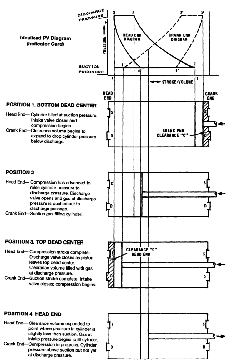
The indexed compressor reference explains each point using piston position and automatic valve action.
4. Point 1 — compression begins
At point 1:
- The cylinder contains a fresh charge.
- Gas is near suction pressure.
- The suction valve has closed.
- The piston begins reducing cylinder volume.
- Compression pressure starts rising.
A normal card begins compression near the suction line, then follows a smooth curve toward discharge pressure.
If the suction valve closes late, compression may begin while the cylinder is still connected to the suction line. This can produce:
- Reduced effective compression
- Reverse flow
- A distorted start-of-compression corner
- Reduced capacity
5. Point 2 — discharge valve opens
At point 2:
- The cylinder pressure has risen above discharge-line pressure.
- The discharge valve opens.
- Compressed gas begins to leave the cylinder.
- The p-V curve changes from compression to discharge.
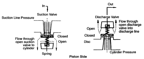
In a real machine, cylinder pressure must exceed line pressure by enough to overcome:
- Valve spring force
- Valve inertia
- Static pressure equalisation
- Port resistance
- Gas acceleration
The higher the pressure difference needed to open the valve, the larger the valve-loss area on the card.
6. Point 3 — discharge ends
At point 3:
- The piston reaches the end of its discharge stroke.
- The discharge valve closes.
- High-pressure gas remains in clearance volume.
- The piston reverses direction.
The discharge line should be approximately horizontal on an ideal card. In reality, pressure may fluctuate because of pulsation, valve dynamics, and discharge-passage resistance.
7. Point 4 — suction valve opens
At point 4:
- Clearance gas has expanded.
- Cylinder pressure has fallen slightly below suction-line pressure.
- The suction valve opens.
- Fresh gas starts entering.
The volume from point 4 to point 1 is the effective suction volume.
If point 4 moves toward point 1, effective intake volume increases.
If point 4 moves farther from point 1, more stroke is consumed by re-expansion and capacity falls.
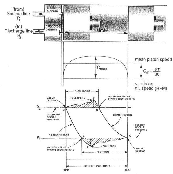
8. Piston position and card volume
The horizontal axis is often shown as volume, piston position, or percentage stroke.
For a single-acting cylinder:
- One dead centre corresponds to minimum volume.
- The opposite dead centre corresponds to maximum volume.
For a double-acting cylinder, the head-end and crank-end cards represent separate working spaces and may be compared for balance.
A card does not simply show time. It shows pressure at each cylinder volume.
9. Area inside the card
The enclosed p-V area represents indicated work.
The actual area includes:
- Compression work
- Discharge-flow losses
- Suction-flow losses
- Valve opening and closing effects
- Leakage effects
- Pulsation distortion
The indexed maintenance text identifies the main enclosed area as compression work and separate areas as energy spent operating valves and overcoming flow resistance.
A larger card area means more work per cycle, provided the same sign convention and scale are used.
10. Ideal card versus actual card
Ideal card
Assumptions:
- No valve pressure drop
- Instantaneous valve action
- No leakage
- Smooth suction and discharge pressure
- Known compression law
- No pulsation
Actual card
Includes:
- Suction pressure loss
- Discharge pressure loss
- Valve inertia
- Delayed opening or closing
- Reverse flow
- Ring leakage
- Pulsation
- Clearance effects
- Heat transfer
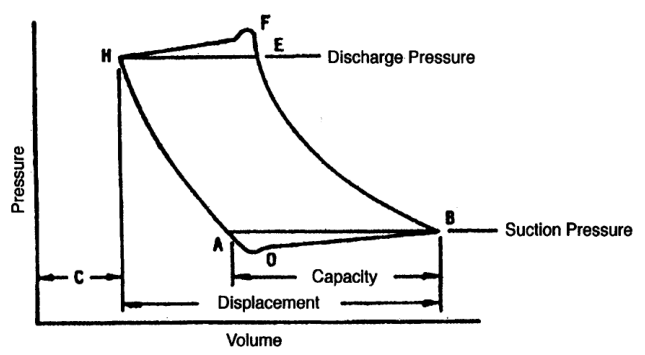
The actual card is the useful diagnostic object; the ideal card is the reference pattern.
11. Suction line on an actual card
The actual cylinder suction pressure may be below suction-flange pressure because gas must pass through:
- Filter
- Suction pipe
- Suction valve
- Valve plate passages
- Cylinder ports
This pressure loss appears as a lower suction line on the card.
Possible causes of excessive suction loss:
- Dirty intake filter
- Small suction pipe
- Restricted silencer
- Stiff or damaged valve spring
- Broken valve plate
- Deposits
- High gas velocity
- Pulsation
12. Discharge line on an actual card
The actual cylinder discharge pressure may be above discharge-flange pressure because gas must pass through:
- Discharge valve
- Valve passage
- Cylinder port
- Discharge nozzle
- Pulsation bottle
- Discharge pipe
Possible causes of excessive discharge loss:
- Fouled valve
- Damaged valve plate
- Weak or incorrect spring
- Restricted port
- Fouled cooler
- Small discharge piping
- High gas velocity
- Pulsation or resonance
Excessive discharge loss increases cylinder work and temperature.
13. Compression-line interpretation
A normal compression line should be smooth and repeatable.
Its shape depends on:
- Gas properties
- Compression exponent
- Cylinder cooling
- Speed
- Clearance
- Ring sealing
- Valve closure
- Pressure pulsation
A compression line that rises too slowly may indicate:
- Suction valve leakage
- Piston-ring leakage
- Unloader operation
- Excessive clearance
A line that rises too quickly may indicate:
- Reduced clearance
- Restricted discharge valve
- Abnormally high cylinder temperature
- Incorrect pressure reference
Interpret the line together with capacity and temperature.
14. Re-expansion-line interpretation
The re-expansion line begins after discharge-valve closure.
It is controlled mainly by:
- Clearance volume
- Trapped-gas pressure
- Re-expansion exponent
- Piston motion
- Leakage through valves or rings
A longer re-expansion region means less fresh gas enters.
Possible causes of increased re-expansion:
- Excessive clearance
- Open clearance pocket
- Increased compression ratio
- Discharge valve closing late
- High discharge pressure
15. Clearance effect on the card
Increasing clearance changes the card by moving suction-valve opening toward the end of the return stroke.
Consequences:
- Shorter effective suction line
- Lower volumetric efficiency
- Lower capacity
- Possible lower total power at the same speed
- Different re-expansion shape
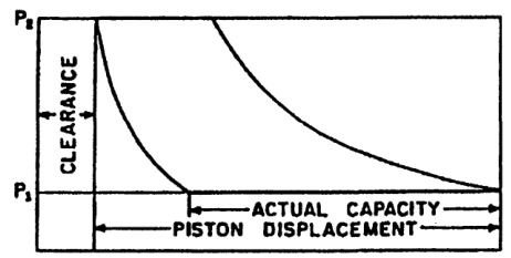
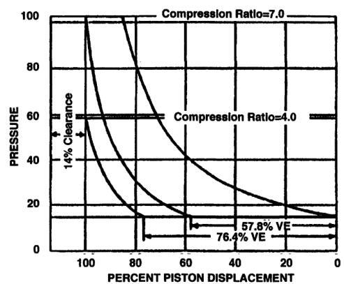
A clearance-pocket card may intentionally show this pattern during capacity control.
16. Suction-valve leakage pattern
A leaking suction valve may allow high-pressure gas to return toward the suction side during compression.
Expected effects:
- Compression line may rise abnormally slowly.
- Suction pressure may be disturbed.
- Capacity falls.
- Suction-valve cover may become hot.
- Incoming gas may be heated.
- Specific power rises.
A leaking suction valve can resemble ring leakage on a card. Confirm with temperature, valve inspection, and comparison with the opposite cylinder end.
17. Suction-valve restriction pattern
A restricted suction valve may cause:
- Low cylinder suction pressure
- Large suction-pressure loss
- Reduced cylinder filling
- Low capacity
- High suction-valve temperature
- Increased inlet velocity
The card may show a suction line substantially below the suction-flange pressure.
Possible causes:
- Broken plate
- Deposits
- Incorrect spring
- Poor lift
- Foreign material
- Fouled filter upstream
18. Discharge-valve leakage pattern
A leaking discharge valve may allow discharge gas to return into the cylinder after the discharge event.
Expected effects:
- Compression line or discharge corner becomes abnormal.
- Discharge temperature rises.
- Capacity falls.
- Valve cover becomes hot.
- Motor power may rise.
- Recompression occurs.
If the valve leaks severely, pressure may fail to hold at the expected discharge line.
19. Discharge-valve restriction pattern
A restricted discharge valve delays gas delivery.
Expected effects:
- Cylinder pressure rises above normal before valve opening.
- Discharge line lies above expected line pressure.
- Discharge temperature rises.
- Card area increases.
- Capacity falls.
- Valve cover may overheat.
This is a high-risk condition because high temperature can accelerate deposit formation and valve damage.
20. Valve spring problems
A spring that is too stiff requires greater pressure difference to open the valve.
A weak or damaged spring may cause:
- Early opening
- Valve flutter
- Poor seating
- Reverse flow
- Impact damage
The troubleshooting reference lists suction/discharge valve springs that are too stiff and valve chatter as faults visible through p-V curves.
Always confirm the correct spring and valve parts for the gas, pressure, and speed.
21. Piston-ring leakage pattern
Piston-ring leakage allows gas to pass across the piston.
Expected effects:
- Compression line may be less steep.
- Capacity falls.
- Cylinder temperature rises.
- Discharge temperature rises.
- Crankcase or opposite-end pressure may increase.
- Specific power rises.
Ring leakage is greatest when pressure difference is high and the piston is near the end of its stroke.
A card alone cannot quantify ring wear reliably; use leakage tests and temperature comparison.
22. Excessive clearance versus ring leakage
| Feature | Excessive clearance | Ring leakage |
|---|---|---|
| Main effect | Long re-expansion | Gas bypasses piston |
| Suction opening | Delayed | May be near normal |
| Capacity | Reduced | Reduced |
| Temperature | May be normal or elevated | Usually elevated |
| Crankcase pressure | Usually normal | May increase |
| Card pattern | Longer 3–4 line | Distorted compression line |
| Check | Bumping clearance | Leakage and ring condition |
Both faults can coexist.
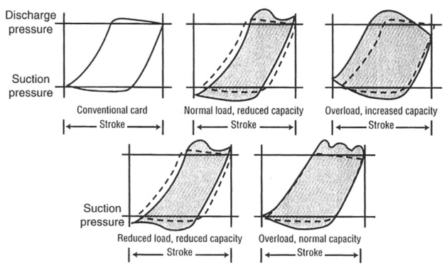
23. Pulsation effects
Reciprocating compressors produce pulsating flow.
Pulsation interacts with piping and bottles, changing cylinder pressure at valve ports.
Effects on the card may include:
- Wavy suction line
- Wavy discharge line
- Multiple pressure peaks
- Delayed valve closure
- Valve chatter
- Apparent load changes
- Card-to-card variation
The indexed reference notes that piping and pulsation can materially change the amount of gas compressed and the horsepower required.
24. Pulsation is not automatically a valve fault
A distorted card may be caused by:
- Valve damage
- Piping resonance
- Poor bottle design
- Nozzle geometry
- Excessive pipe length
- Restriction
- Multiple cylinders interacting
- Operating away from design flow
Do not replace a valve solely because the card is wavy.
Compare:
- Adjacent cylinder cards
- Pressure at cylinder and flange
- Vibration spectrum
- Operating speed
- Piping configuration
25. Pressure versus crank angle
A pressure-versus-crank-angle trace uses time or crank angle instead of volume.
It helps identify:
- Valve opening angle
- Valve closing angle
- Pressure pulsation
- Compression timing
- Discharge duration
- Re-expansion duration
A crank-angle trace is particularly useful when piston position is known accurately or when combined with vibration and ultrasonic measurements.
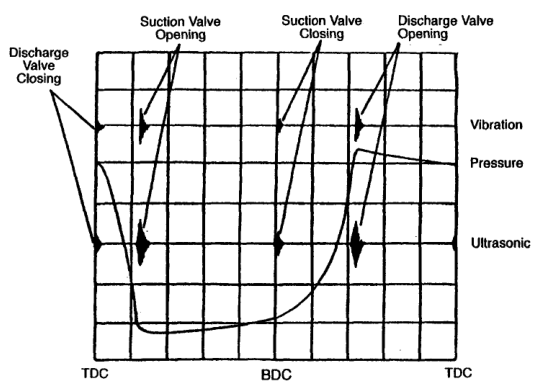
26. Vibration and ultrasonic correlation
Valve opening and closing generate mechanical and acoustic events.
Combining:
- p-V trace
- Crank-angle pressure
- Accelerometer signal
- Ultrasound
- Valve-cover temperature
can distinguish:
- Normal valve motion
- Delayed valve opening
- Valve chatter
- Valve impact
- Leakage
- Pulsation-induced closure
The compressor reference recommends combining p-V patterns with vibration and ultrasonic patterns to diagnose valves, rings, and packing.
27. Discharge-valve pulsation
Pulsation can hold a discharge valve open or cause it to close abnormally.
Possible consequences:
- Gas returns to the cylinder.
- Valve plate impacts the seat.
- Discharge temperature increases.
- Card discharge line becomes irregular.
- Valve fatigue accelerates.
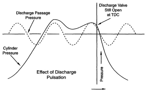
Pulsation-control changes should be assessed with the machine at the affected operating condition.
28. Actual card and horsepower
The card area can be used to estimate indicated horsepower:
For a double-acting cylinder, calculate the head-end and crank-end work separately and add them.
The result must be corrected or interpreted with:
- Indicator calibration
- Pressure-reference accuracy
- Volume scale
- Cylinder geometry
- Speed
- Gas leakage
- Card distortion
A larger card does not necessarily mean more useful air delivery. A leaking or restricted cylinder can draw high power while delivering little gas.
29. Card area and valve loss
The ideal card assumes gas enters and leaves without pressure loss.
Actual valve losses add work:
- Suction pressure is lower than flange pressure.
- Discharge pressure is higher than flange pressure.
- The compression loop becomes wider.
- Indicated work rises.
Valve loss depends on:
- Gas density
- Gas molecular weight
- Valve area
- Piston speed
- Port geometry
- Valve lift
- Pulsation
The compressor reference identifies gas density and valve velocity as major fluid-loss factors.
30. Card comparison between cylinder ends
For a double-acting cylinder, compare:
- Head-end card
- Crank-end card
- Suction pressure
- Discharge pressure
- Re-expansion
- Valve timing
- Card area
A large difference may indicate:
- One valve fault
- Different clearance
- Piston-ring leakage
- Packing problem
- Rod alignment issue
- Cylinder cooling difference
- Instrument-channel error
Use the same pressure and volume calibration for both ends.
31. Card comparison between stages
In a multistage compressor compare:
- LP-stage card
- HP-stage card
- Interstage pressure
- Stage discharge temperatures
- Stage capacity
- Stage work
A weak LP card may cause low interstage pressure.
A weak HP card may cause high interstage pressure.
Unequal card area suggests unequal stage work and may explain vibration or temperature differences.
32. Card patterns and likely faults
| Card observation | Likely direction |
|---|---|
| Long re-expansion | Excessive clearance or high ratio |
| Low suction line | Suction restriction or valve loss |
| High discharge line | Discharge restriction or valve loss |
| Slow compression rise | Suction leakage, ring leakage, unloader |
| Irregular discharge line | Pulsation, chatter, discharge valve fault |
| Card area high | Excess work, valve loss, leakage, high ratio |
| Card area low with low capacity | Unloading, low suction density, severe filling loss |
| Head/crank ends unequal | Local valve, ring, clearance, or packing problem |
| Card changes with piping condition | Pulsation or resonance |
These are screening directions, not final diagnoses.
33. Troubleshooting workflow
Step 1 — Verify the card
Check transducer calibration, channel assignment, pressure range, volume reference, and crank-angle reference.
Step 2 — Stabilise operation
Record pressure, temperature, speed, load, and control position.
Step 3 — Compare baseline
Use a known-good card at the same operating condition.
Step 4 — Compare cylinder ends
For double-acting machines, compare head and crank ends.
Step 5 — Compare stages
Check interstage pressure and stage temperature.
Step 6 — Add physical evidence
Use valve temperature, vibration, ultrasound, leakage, and capacity.
Step 7 — Inspect safely
Only after isolation, depressurisation, lockout, and safe barring procedures.
34. Instrumentation errors
A false p-V fault can result from:
- Wrong pressure transducer range
- Blocked impulse passage
- Wrong cylinder channel
- Incorrect crank-angle pickup
- Phase error
- Volume-scale error
- Electrical noise
- Pressure pulsation at the sensor
- Sensor temperature drift
- Incorrect dead-centre reference
Validate the measurement system before changing machine components.
35. Card repeatability
A healthy cylinder operating at stable conditions should produce repeatable cards.
Poor repeatability may indicate:
- Pulsation
- Valve chatter
- Unstable unloaders
- Control cycling
- Loose sensor connection
- Mechanical looseness
- Intermittent liquid carryover
- Variable suction or discharge pressure
Capture multiple cycles and compare the spread.
One abnormal cycle may be noise; a repeatable abnormal pattern is more significant.
36. Indicator-card example: low capacity
Observation
- Capacity low
- Motor power normal
- Long re-expansion line
- Suction and discharge lines otherwise smooth
Likely direction
Excessive clearance or open clearance pocket.
Checks
- Capacity-control position
- Bumping clearance
- Cylinder-head gasket or shim condition
- Compression ratio
- Piston position
37. Indicator-card example: high power
Observation
- Capacity slightly low
- Motor power high
- Discharge line above normal
- Discharge temperature high
Likely direction
Discharge-valve restriction or high discharge pressure.
Checks
- Discharge valve and spring
- Discharge passage
- Cooler and piping
- Receiver pressure
- Pressure-gauge calibration
38. Indicator-card example: ring leakage
Observation
- Compression line rises slowly
- Capacity low
- Cylinder temperature high
- Crankcase pressure elevated
- No major suction-line restriction
Likely direction
Piston-ring leakage.
Checks
- Ring condition
- Cylinder bore
- Ring end gap
- Ring orientation
- Lubrication
- Blow-by measurement
39. Indicator-card example: pulsation
Observation
- Card has waves on suction and discharge lines
- Pattern changes with speed
- Valve-cover temperatures are similar
- Piping vibrates at the same operating speed
Likely direction
Pulsation or piping resonance rather than a single valve failure.
Checks
- Pulsation bottle condition
- Nozzle size and length
- Pipe supports
- Operating speed
- Acoustic resonance
- Pressure traces at different locations
40. Indicator-card example: stage imbalance
Observation
- LP card area is high
- Interstage pressure is high
- HP card area is low
- Final capacity is low
Likely direction
HP stage is not accepting or compressing gas effectively.
Checks
- HP suction valve
- HP cylinder clearance
- HP piston rings
- Interstage passage
- HP discharge valve
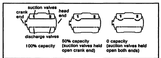
41. Clearance-control card
When a clearance pocket is opened:
- Re-expansion line extends.
- Point 4 moves toward the end of the stroke.
- Effective suction volume decreases.
- Capacity falls.
- Card shape changes intentionally.
A control-system card must be compared with the correct load-state reference, not with the full-load card.
42. P-V interpretation and maintenance
Use indicator cards to prioritise maintenance:
Immediate attention
- Severe discharge pressure rise
- Rapidly increasing card area
- High discharge temperature
- Valve chatter or impact
- Liquid-related distortion
- Card instability with vibration
Planned investigation
- Gradual capacity decline
- Increasing re-expansion
- Slowly increasing valve loss
- Head/crank-end imbalance
- Rising specific power
Normal condition
- Repeatable card
- Stable pressure losses
- Expected area
- Balanced cylinder ends
- Capacity and power within baseline
43. Safe use of indicator equipment
Before connecting or removing instrumentation:
- Isolate the cylinder if required.
- Depressurise the correct chamber.
- Confirm sensor pressure rating.
- Use compatible fittings.
- Prevent hot-gas exposure.
- Route cables away from moving parts.
- Verify crank-angle pickup.
- Keep personnel clear during operation.
After testing:
- Remove temporary connections safely.
- Restore plugs and seals.
- Check for leaks.
- Confirm the compressor is ready for service.
44. Revision questions with answers
Question 1
What does a p-V diagram plot?
Answer: Cylinder pressure against cylinder volume during a cycle.
Question 2
What does the enclosed card area represent?
Answer: Indicated compression work per cycle.
Question 3
What occurs from point 1 to point 2?
Answer: Compression with both valves closed.
Question 4
What occurs from point 2 to point 3?
Answer: Discharge through the discharge valve.
Question 5
What occurs from point 3 to point 4?
Answer: Re-expansion of clearance gas.
Question 6
What occurs from point 4 to point 1?
Answer: Suction or fresh-gas intake.
Question 7
What does a long re-expansion line suggest?
Answer: Excessive clearance, high compression ratio, or a clearance pocket open.
Question 8
What does a low suction line suggest?
Answer: Suction restriction or suction-valve pressure loss.
Question 9
What does a high discharge line suggest?
Answer: Discharge restriction, valve loss, or high discharge resistance.
Question 10
What does a wavy card suggest?
Answer: Pulsation, valve chatter, resonance, or unstable operation.
Question 11
What does a slowly rising compression line suggest?
Answer: Leakage, unloading, poor suction-valve closure, or ring leakage.
Question 12
Why should head- and crank-end cards be compared?
Answer: To identify a local cylinder-end fault.
Question 13
Why must a card be compared at the same operating condition?
Answer: Pressure, speed, load, temperature, and control state change card shape.
Question 14
What additional measurements support card diagnosis?
Answer: Capacity, power, temperature, vibration, ultrasound, and valve-cover temperature.
Question 15
What must be checked before condemning a valve from a card?
Answer: Instrument calibration, piping pulsation, pressure conditions, and other physical evidence.
45. Self-test scenarios
Scenario A — extended re-expansion
Check:
- Clearance pocket
- Bumping clearance
- Compression ratio
- Discharge pressure
- Piston position reference
Scenario B — large discharge-pressure loop
Check:
- Discharge valve
- Valve spring
- Discharge port
- Cooler and piping
- Pulsation bottle
- Receiver pressure
Scenario C — low suction pressure with high valve temperature
Check:
- Suction valve
- Intake filter
- Suction pipe
- Valve spring
- Deposits
- Gas velocity
Scenario D — card wavy but capacity normal
Check:
- Piping resonance
- Pulsation bottles
- Sensor mounting
- Pressure-transducer response
- Operating speed
Do not immediately remove the valve.
Scenario E — unequal cards on a double-acting cylinder
Check:
- Head- and crank-end clearance
- Valves
- Rings
- Packing
- Rod alignment
- Cooling
- Instrument channels
46. Indicator-card watchkeeping checklist
Record:
- Suction pressure
- Discharge pressure
- Stage pressure
- Suction temperature
- Discharge temperature
- Speed
- Load state
- Unloader position
- Capacity
- Motor kW
- Valve-cover temperatures
- Vibration
- Condensate condition
- Card repeatability
- Any change from baseline
Use card data to find trends before a capacity or safety trip occurs.
47. Chapter-eight study checklist
- ☐ Define an indicator card.
- ☐ Draw an ideal p-V diagram.
- ☐ Label points 1–4.
- ☐ Explain compression.
- ☐ Explain discharge.
- ☐ Explain clearance-gas expansion.
- ☐ Explain suction.
- ☐ Explain card area and work.
- ☐ Explain suction-valve pressure loss.
- ☐ Explain discharge-valve pressure loss.
- ☐ Identify excessive-clearance pattern.
- ☐ Identify suction-valve fault pattern.
- ☐ Identify discharge-valve fault pattern.
- ☐ Identify ring-leakage pattern.
- ☐ Identify pulsation pattern.
- ☐ Compare head- and crank-end cards.
- ☐ Compare LP- and HP-stage cards.
- ☐ Explain crank-angle traces.
- ☐ Combine card, temperature, power, and vibration evidence.
- ☐ Verify instrument calibration.
- ☐ Apply safe test procedures.