
Piston-Rod Packing and Oil Scraper in Compressors
Packing leaks by design and seals by pressure, while the scraper keeps the oil where it belongs.
Key Principles at a Glance 7 points
- Pressure packing seals against the cylinder pressure while the rod moves through it, so it needs a controlled leakage path and a vent rather than a perfect seal.
- The oil scraper is a separate function, because it returns crankcase oil to the crankcase and keeps it out of the gas end.
- Packing life depends on rod surface finish and straightness, so a scored or oval rod destroys new rings quickly and the rod is checked before packing is replaced.
- Packing overheating comes from excessive ring tension, loss of cooling or lubrication, or too little leakage clearance, while excessive leakage usually means worn or wrongly fitted rings.
- Packing-case venting and buffering protect the gas end from air ingress and prevent leakage from building pressure in the crankcase.
- Non-lubricated packing relies on gas-end separation, so ring material, cooling and rod finish are even more critical than in a lubricated machine.
- Packing must be installed with the correct ring orientation, staggered joints and specified clearances, because most early packing failures are assembly errors.
Learning objectives
By the end of this chapter you should be able to:
- explain why piston-rod packing is required;
- distinguish pressure packing from oil-scraper or wiper packing;
- describe lubricated, mini-lubricated, micro-lubricated, and non-lubricated packing;
- explain packing-case venting, buffering, and cooling;
- identify the effects of rod finish, taper, runout, and diameter on sealing;
- diagnose packing leakage, overheating, and oil carryover; and
- outline a safe packing inspection, installation, and break-in procedure.
1. Packing in the compressor boundary
A reciprocating compressor has a moving piston rod passing between the cylinder and the frame. The rod must move continuously while the machine contains pressure on one side and crankcase oil on the other. Piston-rod packing provides the controlled seal at this boundary.
Packing has two related but opposite duties:
- contain compressed gas and prevent unacceptable leakage to the frame or atmosphere; and
- prevent crankcase oil from travelling along the rod into the cylinder and gas stream.
The complete boundary normally includes:
Packing is a precision component. It depends on the piston-rod surface, ring geometry, cup faces, lubrication, cooling, venting, alignment, and assembly. A packing leak is often a symptom of rod runout, poor finish, wrong clearance, contamination, or incorrect installation.
2. Pressure packing
Pressure packing is a stack of segmented rings held in cups or a packing case. The rings contact the piston rod and reduce gas flow along the rod.
2.1 Packing-ring action
Packing rings seal through:
- contact between ring bore and rod surface;
- contact between ring faces and cups or adjacent rings;
- gas pressure acting on ring segments; and
- controlled ring spring force or garter-spring loading.
The ring assembly must remain free enough to accommodate rod motion and thermal expansion, but tight enough to control leakage.
2.2 Typical cup-type arrangement
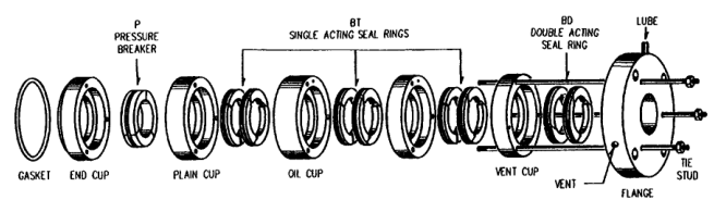
A cup-type assembly may include:
- end cup;
- pressure rings;
- single-acting seal rings;
- double-acting seal rings;
- breaker or lantern rings;
- gaskets;
- cooling passages;
- oil or water connections; and
- vent passages.
The order and orientation of the rings are pressure-sensitive. Reversing a ring segment or cup can create a direct leakage path.
2.3 Ring segmentation
Packing rings may be split into two or more segments. Tangential cuts, radial cuts, and special overlap arrangements are used to prevent a straight gas path through the ring.
Segment ends must match correctly. Factory match marks or letters must be followed during assembly. A ring assembled with reversed or mismatched segments may look complete but leak severely.
2.4 Packing-ring materials
Materials are selected for pressure, temperature, gas composition, rod speed, lubrication, and allowable leakage. Metallic, carbon, Micarta, PTFE, and other engineered materials may be used.
Material changes require compatibility review. A material that works in a lubricated air compressor may fail in a dry, hot, oxygen, hydrogen, or chemically aggressive service.
3. Oil scraper or wiper packing
Oil-scraper rings are located toward the frame side of the packing arrangement. They wipe oil from the reciprocating piston rod and return it to the crankcase or controlled drain.
3.1 Oil-scraper duties
The scraper system:
- limits oil migration from the frame;
- returns oil to the crankcase;
- protects the gas-end packing from excessive oil;
- reduces oil carryover into the cylinder; and
- assists separation between lubricated running gear and clean gas service.
A typical gland is designed with a small total side clearance so the rings can float on the rod. If clearance is too small, the rings cannot follow the rod. If clearance is too large, the rings may pump oil instead of wiping it.
3.2 Scraper-ring construction
A scraper assembly may include:
- scraper rings;
- a gland or housing;
- oil-return passages;
- a deflector collar or slinger;
- drain connections; and
- vent or inspection openings.
The rod surface must be smooth. Nicks, dents, circumferential scores, or excessive taper prevent the scraper rings from maintaining a controlled contact.
3.3 Oil carryover
Oil reaching the cylinder can cause:
- carbon deposits;
- valve sticking or leakage;
- contaminated delivered air;
- downstream filter loading;
- increased fire risk in discharge piping; and
- incorrect operation of oil-free process equipment.
Oil at the scraper drain can be normal. Oil appearing in the gas stream, packing vent, or receiver is not automatically normal and should be investigated.
4. Packing lubrication classifications
Packing may be classified by how much oil reaches the rings.
4.1 Fully lubricated packing
Oil is supplied from a mechanical lubricator to the packing case. The case and cups are drilled so oil reaches the ring surfaces. This reduces friction and heat for packing materials that require a lubricating film.
The flow rate must be sufficient but not excessive. Over-lubrication can increase oil carryover and deposits.
4.2 Mini-lubricated packing
Mini-lubricated packing receives a reduced oil flow compared with fully lubricated packing. It is used when a lower oil rate is acceptable for the material and service.
The reduced rate must be confirmed by the manufacturer. It is not safe to convert a fully lubricated arrangement by simply closing the oil valve.
4.3 Micro-lubricated packing
Micro-lubricated packing receives no direct feed. A small amount of oil may reach the packing by migration along the rod from the frame. It depends on the ring material and surface condition to operate with minimal lubrication.
4.4 Fully non-lubricated packing
No oil is supplied to the packing, and crankcase oil is prevented from reaching it. An oil-deflector collar, scraper arrangement, and distance piece control oil migration.
Non-lubricated packing materials may establish a low-friction transfer film on the rod. Introducing oil after a dry film has formed can change the friction and wear behaviour. Conversely, withdrawing oil from a system designed for lubrication can cause rapid overheating and failure.
5. Packing cooling
Packing converts sliding friction and gas-throttling work into heat. Cooling is required when the heat cannot be safely removed through the rod, case, and surrounding structure.
5.1 Oil-cooled packing
Coolant flows through passages inside or around the packing cups. Oil may come from the frame cooling system or a separate circuit. The system must prevent coolant leakage into the gas stream and maintain the specified flow.
5.2 Water-cooled packing
Water passes through passages in the cups or packing case. The flow path is arranged to cool the hottest regions first. Water quality, corrosion, leakage detection, and pressure separation are important.
A water leak into the gas end can damage rings and cylinders. A loss of cooling can overheat the packing and rod.
5.3 Thermosyphon cooling
Thermosyphon packing uses natural convection through a coolant circuit. A sight gauge or level indicator confirms coolant availability. The system must have the correct elevation, venting, fill level, and heat-rejection capacity.
5.4 Cooling-control principle
The objective is not maximum coolant flow. The objective is a stable packing temperature within the manufacturer’s limit. Excessive water flow can waste water, cause thermal shock, or mask a leakage problem.
6. Packing-case venting and buffering
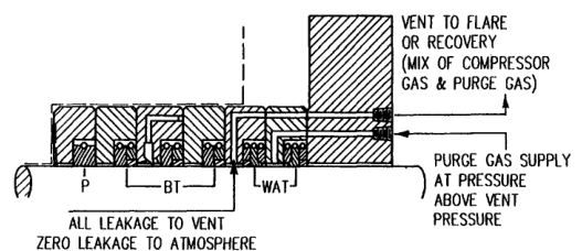
The packing case may be vented to atmosphere, a recovery system, a flare, a safe drain, or a controlled collection point. Venting prevents pressure from building between rings and provides a path for controlled leakage.
6.1 Normal venting
For ordinary air service, leakage may be vented to a safe location. The vent must remain open and free of obstruction. A blocked vent can increase pressure in the packing case and force gas or oil past the wrong sealing boundary.
6.2 Dangerous or valuable gas
For toxic, flammable, expensive, or environmentally controlled gas, the packing case may use:
- leakage collection;
- buffered venting;
- pressure-balanced intermediate spaces;
- an inert-gas barrier; or
- recovery to the process.
The vent system must be designed for the gas properties and pressure. Never discharge hazardous gas into an occupied machinery space.
6.3 Vacuum service
If cylinder suction pressure is below atmospheric pressure, poor packing or venting can draw air into the cylinder. Air ingress may contaminate the gas, create an explosive mixture, or upset process composition.
A buffer or controlled vent can prevent unwanted air entry. The required arrangement depends on suction pressure and gas hazard.
7. Piston-rod surface requirements
Packing can seal only against the surface it receives. Rod diameter, straightness, hardness, finish, taper, eccentricity, and runout are critical.
7.1 Surface finish
The rod must be smooth enough to avoid rapid ring wear but suitable for retaining the intended transfer film. Roughness, plating condition, and hardness are selected for the packing material.
A rod with circumferential grooves can act like a pump and carry oil or gas past the rings. Longitudinal scratches provide leakage channels and damage ring edges.
7.2 Rod diameter
Packing rings are matched to the rod diameter. An undersized rod may allow leakage at ring cuts and reduce contact pressure. An oversized rod may cause segment ends to ride improperly, leaving a leakage path along the bore.
Packing cannot compensate indefinitely for a rod outside its permitted diameter range.
7.3 Taper
A tapered rod contacts one edge of a packing ring while the other edge separates from the rod. This produces a leakage path along the ring bore. Small taper may wear in under some conditions, but excessive taper causes persistent leakage, loss of lubrication film, and overheating.
7.4 Runout and eccentricity
Rod runout is lateral movement or deviation from the intended centreline during operation. Excessive runout prevents packing rings from maintaining uniform contact and can cause:
- leakage;
- ring pounding;
- overheating;
- rod scoring;
- rapid wear; and
- packing-case damage.
Runout may be caused by a bent rod, misaligned frame and cylinder, worn crosshead guide, foundation movement, loose piston connection, or bearing clearance.
8. Packing leakage
Some packing weepage may occur during normal operation, especially during break-in. The trend, temperature, gas hazard, and collection rate determine whether it is acceptable.
8.1 Leakage causes
Common causes include:
- worn packing rings;
- insufficient or incorrect lubrication;
- dirt between ring and cup faces;
- rapid pressure increase during start;
- reversed or mismatched segments;
- incorrect side or end clearance;
- blocked vent system;
- scored piston rod;
- excessive rod runout;
- tapered or undersized rod;
- damaged cups or gaskets;
- inadequate cooling; and
- excessive cylinder pressure.
8.2 Leakage versus overheating
Leakage can be both a symptom and a cause. Gas escaping through a poor fit can blow away the oil or transfer film. The rings then run dry, heat rises, rings expand, and leakage increases further.
A small leak should not be corrected by simply tightening the packing case. Excessive compression can restrict ring movement, increase friction, and damage the rod.
8.3 Leakage measurement
Trend:
- packing temperature;
- vent flow or collection rate;
- oil drain rate;
- rod surface condition;
- gas composition at the vent; and
- leakage changes with load and speed.
A sudden change after a maintenance action is especially significant.
9. Packing overheating
Packing temperature rises when friction, pressure leakage, or cooling loss increases.
Possible causes:
- dry or insufficiently lubricated rings;
- incorrect lubricant;
- blocked oil or water cooling;
- excessive ring squeeze;
- rod runout or taper;
- rough rod surface;
- contaminated packing;
- pressure increase too quickly; and
- ring misassembly.
Overheating can destroy the transfer film, distort rings, damage cups, score the rod, and ignite deposits in hazardous service.
Check temperature at several packing locations where possible. A single cool external surface does not prove the internal ring stack is cool.
10. Packing installation
Packing installation requires precision and cleanliness.
10.1 Preparation
Before installation:
- isolate and depressurise the compressor;
- inspect the rod and packing case;
- clean cups, rings, grooves, and faces;
- confirm correct ring set and pressure orientation;
- inspect springs and garters;
- verify rod diameter and surface; and
- prepare new gaskets where required.
Do not use sharp chisels to separate cups or scrape sealing faces. Nicks and scratches become leakage paths.
10.2 Ring assembly
Follow the manufacturer’s match marks. Ensure:
- ring segments are correctly paired;
- cuts are oriented correctly;
- pressure sides face the required direction;
- side clearance is within limit;
- end clearance is correct;
- garter springs are free in their grooves; and
- rings are not cracked, chipped, or distorted.
The ring bore should normally be only slightly larger than the rod. Some packing is lapped to the rod to reduce initial blow-by.
10.3 Packing-case installation
Tighten packing-case nuts evenly so the case bore remains centred on the rod. Check clearance between case bore and rod at the head end, centre, and crank end of the stroke.
Connect oil, coolant, drain, and vent lines. Fill or prime lubrication lines before starting. Confirm that drains and vents are open and correctly routed.
10.4 Break-in
New packing may require a controlled break-in. Start at the specified unloaded or reduced-load condition, establish lubrication and cooling, and increase load gradually. Applying full pressure immediately can damage new rings before their surfaces conform to the rod.
Monitor temperature and leakage continuously during break-in. Stop if temperature rises abnormally or leakage increases rapidly.
11. Oil-scraper maintenance
11.1 Scraper inspection
Inspect:
- ring face and bore condition;
- side clearance;
- ring end gap;
- gland bore;
- rod surface;
- oil-return holes;
- deflector collar;
- drain passages; and
- vent condition.
The scraper rings must float sufficiently to follow the rod. Too little clearance prevents movement; too much allows oil pumping.
11.2 Oil-return path
Oil removed from the rod must return freely to the crankcase or a controlled drain. A blocked drain allows oil to accumulate, increasing the chance of carryover into the pressure packing and cylinder.
Check for sludge, carbon, gasket fragments, and paint or sealant blocking the passage.
11.3 Deflector collar
A collar or slinger mounted on the rod can interrupt capillary oil migration. It must be secure, correctly positioned, and free from damage. A loose collar can contact the housing or fail to throw oil away from the gas end.
12. Non-lubricated packing and gas-end separation
An oil-free cylinder does not imply an oil-free frame. The frame may use normal pressure lubrication for crankshaft bearings, connecting rods, and crossheads. The distance piece, scraper, deflector, and packing prevent that oil from reaching the cylinder.
The separation system must manage:
- oil migration along the rod;
- gas leakage toward the frame;
- packing vent flow;
- condensate and drain collection; and
- inspection access.
Piston-rod alignment is especially important. Excessive lateral movement prevents non-lubricated packing from sealing and can damage low-friction ring materials.
13. Fault diagnosis table
| Observation | Likely packing/scraper causes | Checks |
|---|---|---|
| High gas leakage | Worn or reversed rings, rod taper, runout, blocked vent | Ring orientation, rod geometry, vent pressure |
| Packing overheating | Dry running, wrong oil, cooling loss, excessive squeeze | Oil/coolant flow, temperature, ring clearance |
| Oil in cylinder | Scraper wear, deflector failure, blocked drain, excess frame oil | Scraper, collar, drain, oil level |
| Oil at packing vent | Scraper or pressure-boundary failure | Vent routing, ring condition, rod finish |
| Rapid ring wear | Dirt, rough rod, misalignment, wrong material | Rod, filter, alignment, ring specification |
| Leakage after overhaul | Mismatched segments, dirty faces, wrong gap, case misalignment | Assembly marks, cup faces, case centring |
| Leakage only at high load | Pressure ratio, rod deflection, inadequate cooling | Load trend, rod runout, packing temperature |
| Leakage during vacuum suction | Air drawn through packing or vent | Buffer pressure, vent arrangement, ring condition |
| Oil scraper pumps oil | Excessive clearance or wrong ring geometry | Side clearance, ring ends, rod surface |
| Packing case vibration | Rod runout, loose case, worn rings, resonance | Rod measurement, fasteners, vibration phase |
14. Worked diagnosis: packing leakage after overhaul
Observation
A compressor receives new packing. During the first hour, packing temperature rises and leakage is higher than before overhaul.
Investigation
- Confirm the machine is operating at the prescribed break-in load.
- Verify correct oil or dry-running arrangement for the packing material.
- Check that the lubricator is primed and delivering to the correct point.
- Confirm cooling-water or oil flow.
- Inspect vent and drain lines for blockage.
- Verify ring segment match marks and pressure orientation.
- Check ring side and end clearance.
- Measure rod diameter, taper, surface finish, and runout.
- Confirm packing-case centring at both rod ends and mid-stroke.
- Inspect cups for nicks, dirt, or damaged gasket faces.
Do not tighten the packing indiscriminately. If the cause is rod runout or wrong ring assembly, more compression will increase heat and accelerate failure.
15. Safety requirements
Packing work can expose personnel to stored pressure, hot surfaces, moving parts, toxic gas, flammable gas, and contaminated oil.
Before work:
- lock out the driver;
- isolate all pressure sources;
- vent and drain the cylinder, packing case, and connected lines;
- verify zero pressure;
- cool hot packing and coolant systems;
- test the atmosphere where hazardous gas is possible;
- prevent crankshaft rotation; and
- use approved lifting and cleaning methods.
Never pull the piston rod through packing or scraper rings without following the maker’s removal procedure. Never use a sharp tool that can nick a cup or sealing face. Do not use gasoline, kerosene, or an unapproved solvent to clean packing components.
16. Revision questions
- What are the two principal functions of piston-rod packing?
- What is the difference between pressure packing and oil-scraper packing?
- Name the main parts of a cup-type packing assembly.
- Why must packing-ring segments be match-marked and assembled correctly?
- What is fully lubricated packing?
- Distinguish mini-lubricated, micro-lubricated, and fully non-lubricated packing.
- Why is packing cooling required?
- Compare oil-cooled, water-cooled, and thermosyphon packing.
- What is the purpose of packing-case venting?
- Why is controlled buffering useful for dangerous gas or vacuum service?
- How does piston-rod taper cause leakage?
- How does piston-rod runout affect packing?
- What happens if the rod is undersized or oversized for the packing?
- List common causes of packing overheating.
- Why should a new packing set be broken in gradually?
- What does the oil scraper prevent?
- What happens if scraper-ring side clearance is too small?
- What happens if scraper clearance is too large?
- Why must oil-return drains remain clear?
- List the checks required after packing-case installation.
- What can cause oil to appear in delivered air?
- Why can leakage be both a symptom and a cause of failure?
- What safety steps are required before packing work?
- Why must sharp tools be avoided when separating packing cups?
- Describe a method for diagnosing leakage after overhaul.
17. Self-test scenarios
Scenario A — packing temperature rises after oil is reduced
Confirm whether the packing is designed for reduced lubrication or fully non-lubricated operation. If it requires a lubricating film, reducing oil has caused dry contact. Check oil flow, ring condition, rod surface, and cooling before restarting.
Scenario B — oil appears in the receiver
Inspect cylinder lubrication rate, scraper rings, oil-deflector collar, distance-piece drains, pressure packing, and downstream separators. A leaking scraper can allow frame oil to reach the cylinder even when pressure packing is healthy.
Scenario C — packing leak increases at the ends of the stroke
Inspect rod taper, rod diameter, and rod runout in the end-of-stroke regions. A rod that is worn or tapered only at the packing travel ends can seal in mid-stroke but leak badly at the extremes.
Scenario D — dangerous gas detected at the packing vent
Follow the approved hazardous-gas response. Isolate and depressurise if safe, verify vent routing and buffer pressure, and inspect packing only under the site’s gas-free and lockout procedure. Do not simply close the vent.
18. Summary
Piston-rod packing is the controlled boundary between cylinder gas and frame oil. Pressure rings limit gas leakage; oil-scraper rings control crankcase oil migration; vents, drains, buffers, and coolers make the seal practical in real service.
Packing reliability depends on the complete system: correct ring material and orientation, clean cups and faces, correct clearances, smooth rod surface, correct diameter, low taper and runout, suitable lubrication, adequate cooling, and clear vent and drain paths.
The safest repair is not the tightest packing. It is the packing system operating at the correct temperature and leakage rate because the rod, case, rings, lubrication, cooling, and alignment are all correct.