
Air Compressor Selection and Application on Ships
Start with the duty and not the catalogue, because most bad compressor choices were made before the enquiry was written.
Key Principles at a Glance 7 points
- A rating such as air compressor, 100 bar is unusable, because discharge pressure, capacity with its basis, duty cycle, air quality, power supply, cooling water, space, weight and control must all be stated.
- Load factor is actual output divided by rated full-load output, and a continuous 100% load factor leaves no reliability margin against a usual design range of about 50 to 80%.
- Single-stage machines are generally used to about 50 psig in moderate-duty service, while two-stage compression to 100 psig saves roughly 10 to 15% power.
- Heavy-duty water-cooled compressors are commonly two-stage for 100 psig air service above approximately 125 bhp.
- Fixed-speed machines usually unload in steps of 0, 50, 75 and 100%, and more steps match demand better but add valves, controls and maintenance points.
- Published maximum figures such as 20,000 bhp and 100,000 psig for reciprocating machines are capability reminders and not selection limits.
- Lifecycle cost decides and not purchase price, because power, cooling water, spares, maintenance access and redundancy over the service life usually outweigh the capital difference.
Learning objectives
By the end of this chapter you should be able to:
- translate a plant or ship requirement into compressor duty data;
- distinguish the selection problem from the purchase-price problem;
- compare reciprocating, rotary, centrifugal, and axial machines at a preliminary level;
- decide when pressure ratio, flow, gas properties, cleanliness, cooling, or control dominates the choice;
- select a sensible number of stages and explain the value of intercooling;
- account for load factor, part-load operation, driver choice, foundation, space, and maintenance;
- specify the information a manufacturer needs before rating a compressor; and
- identify common selection errors before equipment is ordered.
1. Selection is an engineering decision
A compressor is normally expected to operate for many years. Its purchase price is only one part of the ownership cost. Electricity or fuel consumed over the operating life can be many times the initial equipment cost, especially on heavy-duty service. A compressor that is cheap to buy but inefficient, poorly controlled, difficult to cool, or expensive to maintain can be the most expensive choice in service.
The selection sequence should therefore be:
- define the gas and duty;
- establish the required flow and pressure envelope;
- identify acceptable compressor families;
- compare staging, cooling, lubrication, control, and driver options;
- check mechanical, foundation, space, and maintenance constraints;
- compare life-cycle cost and availability; and
- obtain a guaranteed performance proposal from suitable manufacturers.
The first choice is commonly between positive-displacement and dynamic compression. A reciprocating compressor is a positive-displacement machine: each cylinder traps a volume and reduces it mechanically. A centrifugal or axial compressor is dynamic: it adds velocity to the gas and converts velocity into pressure. The pressure, capacity, gas properties, and operating range determine which family is appropriate.
Design rule: never select a compressor from discharge pressure alone. Pressure, flow, suction conditions, gas composition, operating hours, control range, and site conditions must be considered together.
2. Required duty data
A manufacturer cannot rate a compressor reliably from a statement such as “air compressor, 100 bar.” The following information is required.
2.1 Gas identity and composition
State whether the gas is atmospheric air, nitrogen, oxygen, hydrogen, natural gas, refrigerant, process gas, or a mixture. For a process gas, provide the composition over its expected operating range.
Important properties include:
- molecular weight or specific gravity;
- compressibility factor;
- ratio of specific heats, k;
- moisture content and dew point;
- corrosive, toxic, flammable, or polymerising constituents;
- entrained liquid or solid particles;
- allowable oil carryover; and
- chemical compatibility with seals, piston rings, valves, and lubricants.
Gas composition can change the suitability and cost of compressor types. Low-density gas generally affects centrifugal machines more severely because the machine may require more stages or a larger size to produce the required pressure rise. A positive-displacement compressor is less sensitive to specific gravity in its basic displacement, although power, rod load, temperature, valve performance, and volumetric efficiency still change.
2.2 Suction condition
Record:
- suction pressure, absolute and gauge where relevant;
- suction temperature;
- altitude or site elevation;
- inlet pressure loss;
- maximum, normal, and minimum suction pressure; and
- whether the suction gas is saturated, superheated, wet, or contaminated.
Compressor capacity is based on the mass entering the machine, while many air ratings are stated as free-air delivery or actual inlet volume. These must not be mixed. A quoted “100 cfm” is incomplete unless its reference pressure, temperature, humidity, and location are stated.
At altitude, atmospheric pressure and absolute inlet pressure decrease. The compressor must handle a larger inlet volume for the same mass flow, and its performance must be derated or the low-pressure cylinder enlarged. A machine suitable at sea level may not deliver the same mass flow at an elevated installation.
2.3 Discharge condition
State:
- required discharge pressure;
- normal and maximum discharge pressure;
- required discharge temperature or maximum permissible temperature;
- pressure losses in aftercoolers, separators, dryers, filters, valves, and piping;
- receiver pressure range; and
- whether the pressure is measured at the compressor flange or at the point of use.
The compressor must produce enough pressure to overcome downstream losses while remaining below the maximum allowable pressure of the weakest component. Do not size the compressor only for the nominal receiver pressure if the system has substantial pressure drop.
2.4 Capacity and demand profile
Give capacity as a mass flow or as a clearly defined standard/free-air volume. State:
- minimum, normal, and maximum demand;
- start-up and peak demand;
- expected future expansion;
- number of operating hours per day and per year;
- whether demand is steady, cyclic, or intermittent;
- required turndown; and
- consequences of loss of pressure.
A ship’s starting-air compressor may run intermittently but must recharge receivers within a specified time. Instrument air may have a smaller flow but stricter cleanliness and dew-point requirements. Workshop air may have a highly variable demand. These services should not be treated as one generic “compressed-air load.”
3. Preliminary compressor-family selection
3.1 Reciprocating compressors
Reciprocating compressors are positive-displacement machines suited to:
- relatively low to very high discharge pressures;
- low to moderate flow per machine;
- high pressure ratio per stage or per machine;
- variable demand with stepped or automatic capacity control;
- process duties requiring several separate streams; and
- applications where a motor-driven machine is convenient.
They provide nearly constant-volume delivery with variable pressure. They are often efficient over a broad range of pressure duties, but have pulsating flow, reciprocating inertia forces, valves, rings, packing, and a greater maintenance burden than a simple dynamic machine.
3.2 Rotary positive-displacement compressors
Rotary vane, screw, lobe, and related machines provide smoother flow than a reciprocating compressor. They are often attractive for moderate pressure and continuous flow. Their suitability depends strongly on oil-free requirements, internal clearances, seal arrangements, speed, and the gas being handled.
A small centrifugal or rotary machine is not automatically preferable to a reciprocating machine. An oil-free or partially lubricated reciprocating design may be better for a small, clean-gas duty where the alternative has an unsuitable sealing system.
3.3 Centrifugal compressors
Centrifugal compressors are dynamic machines commonly selected for large continuous flows. They have no reciprocating inertia forces and can have a relatively simple foundation requirement, but their performance is sensitive to suction conditions, gas density, operating point, and surge margin.
If suction pressure rises, the discharge pressure and horsepower may exceed the design point. If suction pressure falls, the machine may fail to reach the required discharge pressure. Suction and discharge pressure variation must therefore be evaluated rather than using only nominal values.
3.4 Axial-flow compressors
Axial compressors are used for very large flows and comparatively modest pressure rise per stage, such as gas-turbine and process applications. They require careful control of operating range and are generally not the first choice for a small marine service-air or starting-air installation.
3.5 Approximate application ranges
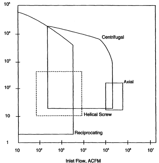
The source text gives broad, non-guaranteed maximum values: reciprocating compressors up to approximately 20,000 bhp and 100,000 psig in special applications; centrifugal machines up to approximately 60,000 bhp and 10,000 psig; and axial-flow machines up to approximately 100,000 bhp and 500 psig. These are not selection limits. They are reminders that the ranges overlap and that other constraints can govern.
4. Pressure ratio and staging
The overall pressure ratio is
where pressures are absolute. A high pressure ratio in one cylinder causes high discharge temperature, reduced volumetric efficiency, greater valve stress, and increased lubrication and deposit problems.
4.1 Single-stage selection
Single-stage compression is suitable when the pressure ratio and discharge temperature remain within the machine’s permissible limits. It is attractive because it has fewer cylinders, valves, coolers, drains, and controls.
For industrial air service, the source notes that single-stage units are generally used to about 50 psig in moderate-duty service, while water-cooled units can reach higher single-stage pressures under appropriate conditions. Exact limits depend on cylinder size, speed, cooling, gas, valve design, and manufacturer rating.
4.2 Multistage selection
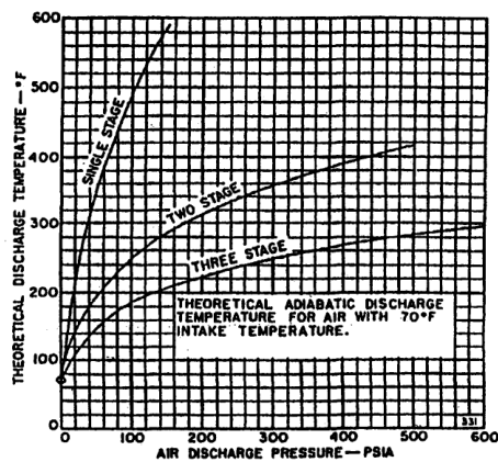
Multistage compression divides the total pressure ratio into two or more stages. With effective intercooling, the gas approaches its original suction temperature before entering the next stage. This reduces compression work and discharge temperature.
For an ideal two-stage arrangement with equal stage pressure ratios:
For N equal stages:
The real optimum must include pressure drops through valves, piping, intercoolers, separators, and coolers. Adding stages indefinitely is not beneficial: after several stages, friction and equipment losses may offset the theoretical saving.
A two-stage compressor delivering air at 100 psig can save approximately 10–15% power compared with single-stage compression under the conditions described in the source. Heavy-duty water-cooled compressors are often two-stage for 100 psig air service above approximately 125 bhp.
4.3 Intercoolers and aftercoolers
An intercooler removes heat between stages. It reduces the inlet temperature of the next stage and lowers the work required. A separator should remove condensed moisture or liquid after cooling so that liquid does not enter the next cylinder.
An aftercooler reduces final discharge temperature after the last stage. Cooling air below approximately 100°F, where practical, allows a substantial amount of moisture to condense before the air reaches the receiver. A moisture separator and reliable drain are then essential.
The selection must include:
- cooler approach temperature;
- cooling-water temperature and fouling allowance;
- pressure drop;
- condensate removal;
- material compatibility; and
- access for cleaning.
4.4 Stage pressure balance
If stage ratios are badly unbalanced, one stage may operate at excessive temperature or power while another is underloaded. Interstage pressure restrictions must be included in the calculation. A blocked cooler, fouled separator, or undersized interstage pipe changes the actual stage pressure and can overload a cylinder.
5. Capacity, load factor, and control
5.1 Rated capacity is not average demand
A compressor selected exactly at the maximum instantaneous demand may spend much of its life lightly loaded, while a compressor selected at the average demand may be unable to maintain pressure during peaks. The installation should be evaluated using a demand profile.
Load factor is the ratio of actual compressed-gas output while operating to rated full-load output during that same period. The source recommends avoiding a continuous 100% load factor and gives a general design range of approximately 50–80%, depending on machine size, type, and number of units.
Benefits of sensible load factor include:
- more uniform pressure during peaks;
- cooling-off periods, especially for air-cooled units;
- reserve capacity for leakage, expansion, and fouling; and
- lower risk of continuous operation at the limiting temperature or rod load.
5.2 Capacity-control methods
Reciprocating compressors can control capacity using:
- start–stop control;
- speed control where the driver permits it;
- suction-valve unloaders;
- suction-valve lifters;
- clearance pockets;
- bypass or free-flow unloading;
- reverse-flow unloading; and
- combinations of these methods.
The control system must sense pressure, relay the demand signal, and actuate the unloading mechanism. Capacity control may be required to limit flow, prevent excessive horsepower, maintain discharge pressure, or protect the driver.
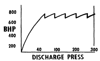
A fixed-speed compressor commonly operates at 0%, 50%, 75%, or 100% capacity through stepped unloading. More steps give closer matching to demand and can reduce wasted power, but add valves, controls, instrumentation, and maintenance points.
5.3 Multiple compressors
Several smaller compressors can provide:
- standby capacity;
- staged operation as demand changes;
- easier maintenance without total loss of service;
- lower minimum turndown; and
- improved response to intermittent ship or plant loads.
A single large machine may have lower installed cost and better efficiency at full load. The correct arrangement depends on reliability requirements, available space, spare philosophy, starting current, maintenance resources, and the demand profile.
Process plants may use one driver to handle multiple streams. Reciprocating machines provide considerable flexibility in the number and size of services connected to a common driver, but the capacity and pressure-control interactions must be analysed.
6. Driver selection
The compressor and driver are one system. Consider:
- electric motor, steam turbine, gas engine, or gas turbine availability;
- starting torque and acceleration time;
- supply voltage, frequency, and short-circuit capacity;
- variable-speed or fixed-speed operation;
- hazardous-area classification;
- waste-heat or exhaust-gas opportunities;
- coupling, gearbox, and alignment requirements;
- overspeed protection;
- emergency or blackout operation; and
- maintenance skill and spare parts.
If the power source dictates the driver, the compressor should be selected to fit that driver. The source notes that a centrifugal machine often receives first consideration when a turbine is required, while a reciprocating compressor often receives first consideration for a motor-driven application. This is a preliminary tendency, not an absolute rule.
The driver must be checked at:
- normal suction and discharge conditions;
- maximum pressure;
- start-up and pull-down conditions;
- unloading and reloading;
- low-voltage or low-steam conditions; and
- fouled cooler or high ambient conditions.
Do not rate the motor only against normal running power. A pressure rise, cooler fouling, or control failure can increase the required power.
7. Cooling selection
7.1 Air cooling
Air cooling avoids cooling-water pumps, strainers, treatment, drains, and freezing risk. It may be appropriate for small or intermittent moderate-duty machines where ambient air is clean and the heat can be rejected safely.
Limitations include:
- dependence on ambient temperature;
- fan power and noise;
- dirty fins and restricted airflow;
- high discharge temperature at high ambient; and
- reduced cooling-off opportunity if the compressor is continuously loaded.
7.2 Water cooling
Water-cooled jackets remove heat from the cylinder and reduce gas temperature. Lower temperature improves lubrication, reduces deposits on valves, extends valve life, reduces cylinder maintenance, and can reduce power. Water cooling also allows higher single-stage pressure under suitable conditions.
The selection must include:
- available flow and pressure;
- inlet temperature and seasonal variation;
- water quality and scaling tendency;
- corrosion control;
- strainers and cleaning access;
- cooling-water failure protection; and
- treatment or chemical cleaning provisions.
A water-cooled heavy-duty unit normally runs at lower speed and temperature than an air-cooled unit of comparable service, so maintenance can be lower. However, a neglected water jacket can foul and create the same overheating problem the cooling system was installed to prevent.
7.3 Cooling-system failure consequences
High discharge temperature can cause:
- less effective lubrication;
- deposits on valves;
- shorter valve life;
- higher cylinder maintenance cost; and
- increased fire risk in discharge piping where oil and deposits are present.
Temperature alarms, high-temperature shutdowns, cooling-water flow indication, and reliable drains should be treated as part of the compressor selection—not as optional accessories added later.
8. Lubrication and gas cleanliness
The required gas cleanliness can determine the cylinder construction. Lubricated cylinders are generally simpler and can have good wear resistance, but oil carryover may be unacceptable for oxygen, breathing air, instrumentation, food, chemical, or catalyst service.
For oil-free service consider:
- non-lubricated piston rings and rider bands;
- separate lubricated frame and crankcase where permitted;
- piston-rod packing and distance pieces;
- labyrinth piston construction;
- oil-removal filters and separators;
- compatibility of materials with the gas; and
- the actual cleanliness guarantee, not merely the label “oil-free.”
Oil-free does not mean maintenance-free. Non-lubricated rings, rider bands, packing, and valves remain wear components. Gas inlet filtration is critical because solids can damage rings and valves, while liquids can cause impact damage, corrosion, and loss of lubrication.
9. Space, weight, foundation, and vibration
9.1 Floor space
Provide the manufacturer with the actual available length, width, and height, not only an approximate room area. Include:
- valve and cylinder removal paths;
- overhead lifting clearance;
- cooler and separator access;
- motor or coupling removal space;
- pipe flexibility;
- control-panel access; and
- safe operator walkways.
A compressor that physically fits but cannot be overhauled in place is not a suitable selection.
9.2 Weight and foundation
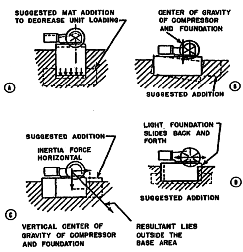
Reciprocating compressors generate inertia forces and couples. The foundation must support dead weight, resist sliding and rocking, maintain alignment, and distribute load safely to the soil. The compressor base, foundation, and connected piping must be considered together.
A centrifugal compressor has no reciprocating unbalanced forces and may require a simpler foundation, although stiffness and alignment remain important. A reciprocating machine may require a heavier foundation, vibration analysis, anchor bolts, and flexible piping supports.
Foundation checks include:
- safe dynamic soil-bearing capacity;
- uniform load distribution;
- centre of gravity and resultant load position;
- resistance to sliding;
- sufficient mass and stiffness;
- temperature effects; and
- avoidance of piping forces being transmitted into the cylinder.
9.3 Pulsation and piping
Pulsating flow is inherent in reciprocating compressors. Piping natural frequencies, pulsation bottles, supports, valves, and branch connections must be analysed. Poor piping can cause vibration, fatigue, valve problems, and inaccurate capacity measurements even when the compressor itself is correctly rated.
10. Marine application examples
10.1 Starting air
Starting-air service requires adequate receiver recharge, high reliability, appropriate discharge pressure, aftercooling, moisture separation, and safe relief protection. The demand is intermittent but the consequence of failure is high. A duty/standby arrangement is often more valuable than one oversized compressor.
Selection questions:
- How many consecutive engine starts must the receiver support?
- What is the required recharge time?
- Is the compressor arranged for automatic start?
- Is condensate removed from the aftercooler and receiver?
- Is oil carryover controlled to reduce deposit and fire risk?
- Can one unit maintain the vessel during maintenance on the other?
10.2 Instrument air
Instrument air requires reliable pressure, low moisture, and low contamination. The compressor package should be evaluated with dryers, filters, drains, receiver volume, and standby philosophy. A compressor with adequate flow but poor moisture control is not adequate instrument-air equipment.
10.3 Workshop and service air
Workshop demand is variable and often includes intermittent high-flow tools. A receiver and stepped capacity control can prevent frequent starts and reduce pressure fluctuation. The compressor should not be sized solely from the sum of tool nameplates; diversity and simultaneous-use factors are needed.
10.4 Emergency and blackout requirements
Where compressed air supports emergency machinery, the selection must include the available emergency power source and restart sequence. A compressor that cannot start against receiver pressure or cannot unload during starting may fail precisely when it is needed.
11. Life-cycle cost
A proper comparison includes:
- compressor and driver purchase price;
- coolers, separators, filters, dryers, receivers, and controls;
- foundations and installation;
- electrical switchgear or steam-system modifications;
- energy cost;
- cooling-water and treatment cost;
- lubricant and filter cost;
- planned maintenance;
- valves, rings, packing, and other spares;
- downtime and lost production;
- training and specialist service; and
- disposal or replacement cost.
Power cost deserves special attention. Even a small efficiency difference becomes significant when the machine operates thousands of hours per year. Compare power at the actual duty profile, not only at rated full load.
A simple annual energy estimate is:
where P_input is the real input power and t_operating is the annual operating time. For variable demand, calculate several load points and apply their operating hours rather than multiplying full-load power by total calendar time.
12. Manufacturer data sheet checklist
The enquiry should request at least:
Process data
- gas name and composition;
- suction pressure and temperature range;
- discharge pressure range;
- capacity at each operating case;
- molecular weight, k, and compressibility;
- moisture, liquid, and solids content;
- allowable oil carryover;
- start-up and upset cases; and
- required availability.
Mechanical data
- compressor type and arrangement;
- number of stages and cylinders;
- cylinder bore and stroke;
- rated speed;
- piston displacement and guaranteed delivered capacity;
- volumetric, mechanical, and overall efficiency;
- rod load and frame load;
- discharge temperature;
- vibration and pulsation limits;
- materials and corrosion allowance; and
- relief-valve and shutdown settings.
Package data
- driver type and rating;
- starting method;
- cooler duties and pressure drops;
- cooling-water requirements;
- lubrication system;
- control philosophy and turndown steps;
- dimensions and maintenance clearances;
- shipping and operating weights;
- foundation loads;
- noise level; and
- spare-parts recommendation.
Guarantees
Require clearly defined guarantees for capacity, power, discharge temperature, vibration, oil carryover, noise, and operating range. State the reference conditions for every guarantee.
13. Common selection mistakes
Mistake 1 — using gauge pressure in the pressure-ratio calculation
Pressure ratios require absolute pressure. Gauge pressure can seriously understate the ratio at low suction pressures.
Mistake 2 — confusing free-air delivery with actual inlet volume
The same mass flow occupies different volumes at different pressures and temperatures. Always state the reference condition.
Mistake 3 — sizing from average demand only
Peak demand, receiver recharge, future expansion, and acceptable pressure dip must be considered.
Mistake 4 — ignoring pressure drop between stages
Intercoolers, separators, valves, and piping alter stage pressure and can overload a stage.
Mistake 5 — selecting air cooling without checking ambient conditions
High ambient temperature, dirty fins, and continuous load can produce unacceptable discharge temperature.
Mistake 6 — treating oil-free as maintenance-free
Oil-free cylinders still require inspection and replacement of rings, rider bands, packing, and valves.
Mistake 7 — selecting the smallest possible foundation
Foundation cost is small compared with the cost of chronic vibration, alignment loss, cracked piping, and repeated shutdowns.
Mistake 8 — comparing purchase prices without energy cost
Power cost over the service life may dominate the economic comparison.
Mistake 9 — forgetting maintenance access
A package that cannot remove a valve, piston, cooler bundle, or motor safely will have excessive downtime.
Mistake 10 — accepting an unqualified performance curve
The curve must identify gas, suction state, discharge state, speed, cooling conditions, and measurement reference.
14. Worked selection approach
Case: marine service-air installation
Assume a vessel requires compressed air for workshop tools, control service, and intermittent pneumatic equipment.
Step 1 — define the pressure
Establish the receiver pressure, minimum pressure at the farthest user, filter and dryer losses, and required compressor discharge pressure. Use absolute pressure for ratio calculations.
Step 2 — define the demand
Separate continuous instrument demand from intermittent tool demand. Determine simultaneous use and identify the worst credible peak.
Step 3 — choose receiver volume
A receiver smooths demand, reduces rapid cycling, and provides short-duration reserve. It does not replace adequate compressor capacity or a recharge-time calculation.
Step 4 — compare compressor families
For moderate flow and a substantial pressure ratio, a reciprocating compressor is a strong candidate. For a large continuous flow with a narrow operating range, a rotary or centrifugal option may deserve comparison.
Step 5 — choose staging and cooling
If the pressure and temperature make single-stage compression severe, select two-stage compression with intercooling, moisture separation, and an aftercooler.
Step 6 — choose the control range
Use start–stop, load–unload, or stepped unloading according to receiver size, motor starts, demand variation, and required pressure stability.
Step 7 — choose redundancy
For safety-related or continuous service, compare one large unit against two or more units with duty/standby or duty-assist operation.
Step 8 — verify installation
Check foundation, vibration, pipe supports, lifting access, ventilation, cooling water, electrical starting current, noise, and maintenance clearances.
Step 9 — compare life-cycle cost
Include energy, cooling, filters, oil, valves, rings, planned maintenance, and the financial consequence of downtime.
15. Revision questions
- Why is compressor selection a life-cycle engineering decision rather than a purchase-price decision?
- What process data must be supplied before a compressor can be rated?
- Why must pressure-ratio calculations use absolute pressure?
- How does altitude affect a reciprocating air compressor?
- When is a reciprocating compressor generally preferred to a centrifugal compressor?
- Why can suction-pressure variation be more critical for a centrifugal compressor?
- What are the advantages of multistage compression?
- Why are intercoolers and moisture separators used between stages?
- Why is adding more stages indefinitely not always economical?
- Define load factor and state why 100% continuous load is undesirable.
- Name four capacity-control methods used on reciprocating compressors.
- What factors influence the choice between air cooling and water cooling?
- Why can water cooling reduce maintenance?
- Why does gas cleanliness influence the choice of cylinder lubrication?
- What foundation and piping issues are associated with reciprocating compressors?
- Why should several smaller compressors sometimes be selected instead of one large unit?
- What should be included in a life-cycle cost comparison?
- List the data that should appear on a compressor enquiry sheet.
- Why is maintenance access part of compressor selection?
- Explain the selection sequence for a marine service-air installation.
16. Self-test scenarios
Scenario A — high flow, modest pressure, continuous operation
A plant needs a very large, steady gas flow at a modest pressure ratio. The correct preliminary comparison is likely between centrifugal and axial-flow equipment, with attention to surge margin, gas density, and operating range. A small reciprocating machine would be an unlikely first choice because many cylinders or units would be required.
Scenario B — low flow, high pressure, variable demand
A process needs a relatively low flow at high discharge pressure and demand varies widely. A reciprocating compressor is a strong candidate because positive displacement suits high pressure and stepped unloading can follow the demand.
Scenario C — clean, oil-sensitive gas
A lubricated cylinder may contaminate the process. Specify non-lubricated or oil-free cylinder construction, distance pieces and packing where required, appropriate filters, and a measurable oil-carryover guarantee. Do not assume that an oil-lubricated frame makes the entire compressor unsuitable; the gas-end and frame can be separated by design.
Scenario D — marine starting air
The correct selection must include recharge time, receiver volume, aftercooling, condensate drainage, automatic starting, duty/standby philosophy, emergency power, and safe discharge protection. Maximum flow alone is not an adequate specification.
17. Summary
Compressor selection begins with the duty, not the catalogue. Establish gas properties, suction and discharge conditions, capacity profile, pressure ratio, operating hours, control range, cooling, lubrication, driver, foundation, space, reliability, and maintenance requirements.
Reciprocating compressors are particularly useful for high pressure, low-to-moderate flow, variable demand, and multiple-service duties. Dynamic compressors are often attractive for large continuous flows, but their operating range and gas-density sensitivity must be checked carefully. Multistaging reduces temperature and power when the pressure ratio warrants it; intercooling, separation, and aftercooling are part of the complete system.
The final selection must balance performance, safety, maintainability, installation constraints, availability, and lifetime power cost. A technically correct compressor is one that performs its duty at the specified conditions for the required life—not merely one that reaches the nameplate pressure.