
Steering Gear Failures — Relief Valves, Split Circuits and the Alarm Chain
The failures a steering gear actually suffers, what has been done about them, and how to read the symptoms when something goes wrong.
Key Principles at a Glance 7 points
- The failure arrives suddenly: a pipe or a flange fails at full pressure and the oil is gone in seconds, with no slow degradation to notice and no time to act.
- The consequence is disproportionate — a small component such as a pipe joint or a flange stud takes away the steering of a ship, and the gear then destroys itself against the sea.
- The first protection is yielding, not stopping: the relief valves let the rudder give way and the hunting gear brings it back, so the gear absorbs the shock and recovers.
- The second protection is division: the circuits are split so that a loss of oil in one half cannot reach the other half, and the split is automatic because there is no time for anything else.
- The third protection is correction — the Donkin second stage exists because the first automatic choice may be the wrong one, and the system has to be able to change its mind.
- The fourth protection is information: the low level alarm, the level 1 alarm and the bridge alarms exist so that people know what has happened.
- The last resort is not a device at all — it is keeping the propeller turning so that the slipstream holds the rudder, because the engine is still part of the steering system.
1. What fails, and why it matters more than usual
The protection devices are set by the maker and tested on a schedule. A relief valve that has been adjusted to stop it lifting, or an isolating arrangement that has been disabled because it operated, is a protection that has been converted into a hazard.
Equipment installed to operate the rudder can be duplicated, but conventional ships have only one rudder and rudder stock. These two items and any others not duplicated must therefore be of a strength sufficient to make failure unlikely.
That is the principle, and it produces two different kinds of design work:
- The un-duplicable parts are over-designed. The rudder, the stock and the tiller are built with a large margin, and they are the components whose failure is treated as not credible. The rules exclude them from the single-failure requirement (Chapter 1) for exactly this reason.
- The duplicable parts are duplicated and protected. The pumps, the rams, the pipes, the valves and the control systems are all arranged so that one of them can fail.
The failure that matters most on a hydraulic gear is the loss of oil.
Hydraulic steering gears, whether of the two or four ram (or double acting) type, or of the single or double chamber vane type, can be rendered useless by loss of oil from the hydraulic system.
That sentence is the whole reason for the duplicated circuits, the split systems, the float switches and the automatic isolation arrangements. Every one of those devices exists because of oil loss, and none of them exists for any other reason.
2. How the oil is lost, and what happens next
The mechanism of the loss is specific, and understanding it is what makes the protection make sense.
The loss, probably resulting from a fractured pipe or failure of flange studs, would be most likely to occur when the pump was on stroke and system pressure high.
So the failure happens at the worst possible moment: when the gear is working hardest and the pressure is highest. A pipe that is sound at no-stroke pressure may fail at full pressure, and a gear spends its time at low pressure and fails at high pressure.
In the Amoco Cadiz it was also thought that an additional surge in system pressure was produced by a heavy sea striking against the rudder, in the opposite direction to that in which it was moving.
Pipe or flange failure at such a time, with the pump perhaps on full stroke, would mean that all of the hydraulic oil would be discharged into the steering compartment in a matter of seconds.
That is the sequence, and it is worth stating plainly: a sea strikes the rudder against its movement, the pressure surges, a pipe or a flange fails, and the entire oil charge is on the floor of the steering flat within seconds. There is no warning and no opportunity to react.
What happens to the ship
In bad weather conditions, the effect of sea and ship movement would be to make rudder and steering gear swing wildly from side to side, with the final result of a smashed gear.
This has happened in a few incidents, with efforts of personnel to rectify the situation being hampered by oil on the deck.
Arresting the movement with a brake is not possible, because the only brake available is that provided by closing valves on the hydraulic system — not effective with no oil in the circuit or cylinders. Very few ships have been fitted with friction brakes.
That is the crucial point, and it is the reason the whole duplicated-circuit philosophy exists. The rudder locking valves, which are described in Chapter 8 as the rudder brake, work by trapping oil. With no oil in the circuit there is nothing to trap, and the valves are useless. The gear is then simply a large mass of metal being driven from side to side by the sea, and it destroys itself.
In one episode, coils of rope were thrown in to finally jam a gear which had lost oil through a fractured pipe, but too late to prevent damage beyond repair.
A vivid illustration of what the failure is actually like. The response is not a valve operation; it is people throwing rope into a machine to stop it moving.
What can be done about it
It is probable that movement of the rudder and steering gear could be cut down by keeping the propeller turning, to maintain forward movement of the ship through the water and therefore a slipstream over the rudder.
That is the practical mitigation, and it is worth knowing. With the ship moving ahead, the slipstream holds the rudder roughly amidships rather than letting it swing. The engine is therefore part of the steering system's failure response: keep the ship moving and the rudder stops flailing.
3. What the statistics say
Statistics show a decrease in hydraulic system reliability with increase in system pressures and age.
High pressures of 170 bar permit small equipment size.
The failures might be due to surges being more extreme in the contemporary high-pressure plant.
There is a genuine trade here, and it is worth being clear about it. Higher pressure means smaller equipment — a gear working at 170 bar needs less than half the ram area of one working at 80 bar for the same torque, so it is smaller, lighter and cheaper. But higher pressure also means more violent pressure surges, because a surge is a proportion of the working pressure and the same proportional surge is a larger absolute one.
Discussion at international level, when considering the single failure concept in relation to the hydraulic system, the major pollution risk with loss of steering on a large tanker, and the statistics of steering gear failure, resolved that it will be necessary to have complete hydraulic system duplication on the largest ships.
That is the origin of the requirement in Chapter 1: the rule came from the statistics, and the statistics came from the casualties.
4. The shock relief valves
The shock relief valves are the first line of protection, and they do two jobs at once.
The relief valves between the pipes connecting the opposing rams are designed to lift if pressure in the system rises to about 10 per cent above normal. This will occur due either to the rudder being hit by a heavy sea or from direct loading.
By-passing of oil from one side of the system to the other through the relief valves permits the rams to move, and abnormal stress on the rudder stock is thereby avoided.
The hunting gear will cause the rudder movement to be corrected by putting the pump on stroke.
So the relief valves protect the rudder stock by letting the rudder give way, and the hunting gear then puts it back. That is a genuinely elegant arrangement: the protection is not a shutdown, it is a yielding. The gear gives way to the shock and then recovers its position by itself, without the helmsman doing anything.
The by-passes are in parallel with the relief valves.
The setting
Two other valves, of the spring loaded type, act as double shock relief valves. Each valve connects both sides of the system when the pressure in either ram cylinder reaches 80 to 190 bar, depending on the design. The valve lifts, so letting the rudder give way when subject to severe sea action.
When giving way, the pump actuating spindle is moved and the pump acts to return the rudder to the previous position when the loading reduces.
The relief valves, when operating, are effectively providing feedback, with increased offset between set and desired values in the short term, which will be reduced as soon as normal conditions prevail, when the relief valves close.
That last sentence is control-engineering language applied to a hydraulic device, and it says something worth understanding: when the relief valves are open, the rudder is not at the angle ordered — it has been pushed off by the sea. The system is temporarily in error, and the error closes as soon as the sea load comes off and the valves shut. The gear is doing exactly what it should: yielding to an overload, then correcting.
The relief valves' lifting pressure setting therefore fixes the maximum loading on the rams. This in turn limits the maximum torque that is exerted on the rudder stock, and the maximum torsional stress is so limited to about 34.5 MN/m².
This is the same chain of reasoning as in Chapter 3, seen from the protection end. The relief valve setting is the number from which the rudder stock's strength is derived. The stock is sized so that it survives the maximum torque the relief valves will allow through. Raise the relief valve setting and the stock is under-sized; the relief valve is therefore a strength calculation as well as a protection.
The gear works on the well-known principle of the Rapson slide, and knowing the maximum lifting pressure of the relief valves then the ram load is fixed, applying the leverage for distance to stock gives the torque exerted, which allows size calculations for the stock diameter, and horse power and sizes for the motor and pump.
Higher pressure systems have relief valves acting at about 190 bar.
So the range of relief valve settings is 80 to 190 bar, and the setting is the design pressure of the whole gear.
5. The duplicated hydraulic circuit
The shock relief valves protect against a shock load. They do nothing at all about a loss of oil, and that is the failure that destroyed ships.
The Amoco Cadiz disaster focused attention on the fact that failure of the common hydraulic pipe system of a four-ram steering gear with duplicated power units could result in rapid discharge of oil from the circuit and loss of steering capability.
The point is subtle and worth stating carefully. A four-ram gear with two pumps is duplicated in the sense that either pump can drive the gear. But if both pumps feed one common pipe system, a single pipe failure takes the whole thing out — the oil from both pumps goes overboard through the same hole. The duplication of pumps was therefore not a duplication of the thing that could fail.
Four-ram or double vane type gears with duplicated hydraulic circuits, as well as duplication of pumps, were developed.
This arrangement cannot, however, be operated with both pumps running and the duplicated hydraulic circuits isolated from each other. The systems have to be connected in common for operation with both pumps.
That is the trade, and it is worth understanding. With the two circuits isolated from each other, each pump drives its own two cylinders, and the ship can only get half the rudder angle at full speed. To get the full performance, the two circuits have to be interconnected — and interconnecting them brings back the common pipe system and the single point of failure.
Either pump can provide hydraulic power for the combined circuit or for an isolated half, with the bypass open on the other part.
So the gear has two modes:
| Mode | Circuits | Performance | Single point of failure? |
|---|---|---|---|
| Combined | Interconnected, both pumps on the whole system | Full torque and speed | Yes — a common pipe |
| Split | Isolated, each pump on its own half | Half the torque | No — each half is independent |
The protection is not to run permanently in split mode. It is to run combined, and to split automatically when a loss of oil is detected. That is the automatic fail-safe split system.
6. The automatic fail-safe split system
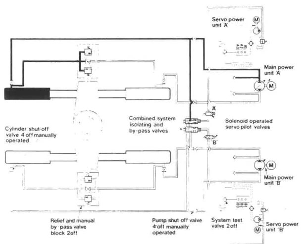
The system is arranged to give two-ram operation automatically in the event of loss of fluid from one system.
Two main power and servo-power units draw from a two-compartment tank, fitted with oil level switches arranged at three levels.
Level 1 — the alarm
Level 1 gives an initial alarm following loss of oil from either system.
In normal operation, one or both power units provide hydraulic power to all four rams.
So the first level does nothing but warn. The gear carries on as it was, with all four rams working and both power units supplying them. The bridge and the engine room are told that oil is being lost.
Level 2 — the split
Continued loss of oil initiates one or both of the level 2 switches. These energize their respective solenoid operated servo valves, causing the combined isolating and bypass valves to operate, splitting the system such that each power unit supplies two rams only.
At the same time, if one power unit is stopped, it is automatically started.
The split happens automatically, and it is worth noticing the second sentence. If one power unit had been stopped — which is normal in open water — it is started automatically at the same moment. That is necessary, because after the split each half needs its own pump; a split system with one pump running would have half the gear dead.
The valves that do it are the combined isolating and bypass valves described in Chapter 4 — the double-seating valves that isolate a cylinder from the main system and open it to a bypass manifold in one movement.
Level 3 — the shutdown
Further loss of oil, and the system on which it is occurring will operate one of the level 3 switches. This will close down the power units on the faulty side.
Steering then continues, uninterrupted but at half the designed maximum torque, on the sound system. The defective system is out of action and isolated.
That is the final state, and it is a good one: half the torque, uninterrupted steering, and the faulty half isolated and out of service. Half the torque means the full rudder angle at reduced speed, or half the rudder angle at full speed — which is a ship that can still be steered, and that is what the requirement in Chapter 1 asks for.
The whole sequence is worth setting out as a table:
| Level | Detection | Action | Result |
|---|---|---|---|
| 1 | Oil loss detected in either system | Alarm only | All four rams still working |
| 2 | Continued loss | Split the circuits; start the stopped pump | Each pump on two rams |
| 3 | Further loss on one side | Shut down the power units on the faulty side | Half torque on the sound system; faulty half isolated |
The three levels give the ship three chances, and each one is taken before the next is needed. That is the difference between a protection and an alarm: the protection acts.
7. The Donkin arrangement
A second version of the same idea is worth knowing because it handles the one case the three-level system cannot: what if the system isolates the wrong half?
Donkin utilise the bedplate oil tank, with a control division plate up to two thirds height, so each side is connected to its own pump.
Each pump is associated with a pair of rams — optionally mounted one above the other to save deck space — so that two complete half power steering gears are formed, giving up to 20° rudder movement at maximum ship speed or full manoeuvring at two thirds maximum ship speed.
The 20° at maximum speed or full manoeuvring at two thirds speed is a useful figure to compare with the full-gear performance, and it is the same trade as everywhere else in this subject: half the actuator gives less angle at high speed, and the full angle at reduced speed.
In normal operation, at full tank, the two systems are joined by two common lines each fitted with a solenoid operated spool valve (normally open), so allowing a free balanced flow of oil between the circuits.
Normally open, so that a failure of the solenoid or its supply leaves the system combined rather than split. That is the fail-safe direction: the valves need power to isolate, so a loss of power leaves the gear at full capability.
First stage
If leakage of oil does occur, the first stop of the oil tank float switch closes, which isolates one of the pump motors and simultaneously closes its associated valve on the line between the two systems, putting the ram cylinders of the suspect circuit into the bypass condition.
Operation is instantaneous with no interruption to steering; audible and visual alarms are fitted on the bridge.
Second stage — the correction
As the choice of circuit isolated is preset, if the incorrect circuit has been chosen, the oil level in the tank will continue to fall and eventually close the second stage of the float switch.
That is the problem the second stage solves, and it is a real one. The float switch cannot tell which half is leaking; it can only see the level falling. So the system isolates one half, on a preset choice — and if that was the wrong half, the level keeps falling.
This at once changes over the pump motors and their corresponding isolating valves, so leaving, by process of elimination, the correct circuit in use.
After the operation of the second stage of the float switch, two thirds of the tank contents still remain, thus ensuring an adequate supply of oil for continued working of the rudder actuator.
The two thirds figure is why the division plate only goes up to two thirds height. If the plate went the full height, isolating one half would leave the other half's oil trapped below the plate and unavailable. With the plate at two thirds, oil can flow over the top of it, and two thirds of the tank's contents remain available to whichever half is working.
As the defective circuit is now completely isolated, any repairs that are necessary can be carried out without interruption to steering.
That last sentence is the operational payoff, and it is worth noting: the gear can be repaired while the ship is still steering on the other half. The faulty circuit is isolated, bypassed and drained, and work can be done on it in the steering flat with the ship under way.
8. The rudder locking valves and the low level alarm
Two further devices complete the protection.
Rudder locking valves on all cylinders are open except in cases of emergency.
The rudder can be locked by closing the supply valves, in an emergency.
The locking valves are the rudder brake (Chapter 8), and their limitation has already been stated: they work by trapping oil, so they are useless if the circuit has lost its oil. Their proper role is to hold the rudder in one position when the gear is otherwise unusable — so that the ship can be steered on the engines — not to save a gear that is losing oil.
A low level alarm must be fitted on each hydraulic fluid reservoir, to give an early audible and visual indication on the bridge and in the engine room of any hydraulic fluid leakage.
This is the rule from Chapter 1, and it is the human-facing half of the automatic protection. The automatic system splits the circuits and keeps the ship steering; the alarm tells the bridge and the engine room what has happened, so that somebody can act. A ship steering on half its gear with nobody knowing why is a ship that will lose the other half next.
9. Reading a fault
The steering gear is a machine with a small number of symptoms and a fairly small number of causes, and most faults announce themselves in a recognisable way.
| Symptom | First checks | Usually turns out to be |
|---|---|---|
| Rudder will not move at all | Pump running? Oil pressure? Control demand reaching the pump? | Pump at no-stroke, no oil, control disconnected, or locking valves shut |
| Rudder moves but very slowly | How many power units running? Oil temperature? | One pump only, cold oil, relief valve lifting, or a partly shut isolating valve |
| Rudder moves the wrong way | Control connections after any work | Control linkage or electrical connections reversed |
| Rudder does not hold its angle | Air in the system? Slide clearances? | Air in the oil, worn Rapson slide or swivel block, or internal leakage past a pump |
| Rudder overshoots and hunts | Hunting gear adjustment and wear | Hunting linkage out of adjustment, worn pins, or air in the system |
| Rudder drifts slowly with the control stationary | Locking valves and internal leakage | Leaking relief valve, worn pump, or a bypass valve not fully shut |
| Gear does not respond to the bridge | Which control is connected? Changeover pin? | Changeover pin in the wrong hole, telemotor bypass wrongly set, or the control system disconnected |
| Pump ammeter reading high | Oil temperature; relief valve; rudder against a stop | Cold oil, relief valve lifting, rudder jammed, or a failing pump bearing |
| Oil pressure low at the gauge | Tank levels; leaks; pump stroke | Loss of oil, pump at no-stroke, or a relief valve stuck open |
| Oil level falling | Where is it going? | A leak — and the location decides whether the gear can still steer |
| Oil level rising | Water from the rudder stock gland? | A leaking gland, or water in the system |
| Noise from the pump | Oil level; air; coupling | Air in the suction, low oil level, or a worn coupling |
| Bridge alarms on power failure | Supply to the unit and its control | A genuine supply failure, or a protection relay that has operated |
| Standby unit does not start automatically | Auto/standby selector position; the changeover valve | Selector out of auto, or a changeover valve stuck bypassed |
| Rudder angle indicator reads wrong | Transmitter linkage; the indicator itself | A loose or slipped linkage, or a fault in the indicator circuit |
| Rudder drop increasing between dockings | Rate of change since last survey | Carrier bearing wear, or a pintle bearing failing |
| Jumping clearance increasing | Cross-check against the rudder drop | The same bearing wear, or a loose component |
Three of these are worth pulling out because they are the ones that catch people.
A rudder that will not hold its angle is usually an air problem or a wear problem, and the two are distinguished by whether the fault came on gradually (wear) or suddenly (air). Air is the more common cause and the easier to fix.
A gear that does not respond to the bridge is usually a changeover pin or a bypass valve, and both are found by looking rather than by testing. This is the failure that caused a collision (Chapter 7), and it is worth checking the obvious things before suspecting the machinery.
An increasing rudder drop and an increasing jumping clearance are the same fault measured twice. When the two agree, the diagnosis is confirmed; when they disagree, something else is moving and it needs finding.
10. The shape of a steering gear failure
Reading this chapter as a whole, the failures and the protections have a recognisable shape.
The failure arrives suddenly. A pipe or a flange fails at full pressure, and the oil is gone in seconds. There is no slow degradation to notice and no time to act.
The consequence is disproportionate. A small component — a pipe joint, a flange stud — takes away the steering of a ship, and the gear then destroys itself against the sea.
The first protection is yielding, not stopping. The relief valves let the rudder give way and let the hunting gear bring it back. Nothing is shut down; the gear absorbs the shock and recovers.
The second protection is division. The circuits are split so that a loss of oil in one half cannot reach the other half, and the split is automatic because there is no time for anything else.
The third protection is correction. The Donkin second stage exists because the first automatic choice may be the wrong one, and the system has to be able to change its mind.
The fourth protection is information. The low level alarm, the level 1 alarm and the bridge alarms exist so that people know what has happened. The automatic system keeps the ship steering; the alarm is what allows somebody to do something about it.
And the last resort is not a device at all. It is keeping the propeller turning so that the slipstream holds the rudder, and it is worth remembering that when everything else has been tried, the engine is still part of the steering system.