
Ram Type Steering Gear — Two and Four Rams, Valve Chests and Change-Over
The ram type gear as a machine — the cylinders and rams, the valve chest, the hydraulic circuit, and the way the gear can be run on two cylinders or four.
Key Principles at a Glance 6 points
- The ram type gear is the most common steering gear on merchant ships, and it is flexible: the torque can be increased by raising the pressure, the ram area or the leverage.
- It adapts to mechanical alternatives — if the hydraulics fail entirely the gear can be worked by hand pumping, by a hand pinion, or by relieving tackles rigged to the tiller.
- It duplicates naturally: two pumps, four cylinders and a valve chest satisfy the single-failure rule without a second gear being fitted.
- Its weaknesses are known and manageable — the hydraulic system can lose its oil, and the gear can then be smashed by the rudder swinging in a seaway.
- The automatic change-over valve is what lets a failed power unit be isolated and the other take over, and the four-ram gear can be changed over to two rams when a cylinder is out of action.
- The replenishing system and the control valve block are what keep the circuit full and the pump stroke under command.
1. The two-ram gear
The valve line-up on a steering gear is a maker's instruction, not a matter of preference. Every valve is either open or shut for a reason, and the line-up is checked before the gear is put into service.
The two-ram gear is the classic arrangement, and it is the one to understand first because everything else is a variation on it.
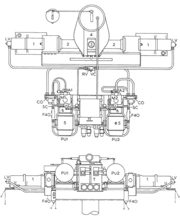
The cylinders for this gear are of cast steel, but the rams comprise a one-piece steel forging with integral pins to transmit the movement through cod pieces which slide in the jaws of a forked tiller end. The cylinder is a casting because it is a complex shape with ports and feet; the ram is a forging because it is a simple shape carrying a large bending and compressive load.
The rams are machined and ground to slide in the gunmetal neck bushes and chevron type seals of the cylinders. Two things matter in that sentence:
- The gunmetal neck bush is the bearing that supports the ram as it slides in and out. It is gunmetal because it is a bearing, and it wears in preference to the ram.
- The chevron type seal is the pressure seal. A chevron seal is a stack of V-shaped rings that seal more tightly as the pressure rises, and it is the part that is renewed at the dry-dock overhaul described in Chapter 10.
Such gears may have a torque capacity of 120 to 650 kNm. That range covers the great majority of merchant ships, and it is the range in which the ram type gear is the natural choice.
2. Where the pressure comes from
Hydraulic pressure is supplied to one cylinder or the other by uni-directional, variable delivery pumps with electric drive, running at constant speed. The phrase uni-directional is the important one: the pump motor always turns the same way. Direction of steering is obtained by reversing the oil flow, not the motor.
The pumps may be the Hele-Shaw radial piston type or a development of the axial piston V.S.G. pump. The strokes of the pump pistons in both types can be varied, and the flow of oil to and from the pump can be reversed.
When the operating rod of the pump is in mid position, there is no flow of oil. That is the no-stroke or neutral condition, and it is the state the gear spends most of its time in. The pump is still running; it is simply not pumping.
The construction and control of these pumps is the subject of Chapter 5.
3. The two-ram hydraulic circuit
The hydraulic circuit of a two-ram gear is worth following properly, because it explains how a gear can have two complete power units and still be controlled by one bridge command.
The power units
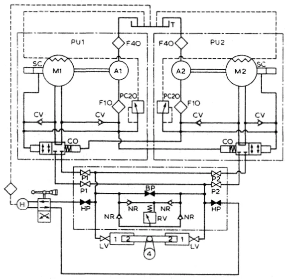
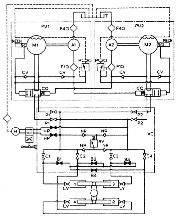
The duplicate power units PU1 and PU2 each have a continuously running electric motor driving, through a flexible coupling, a variable delivery axial-cylinder pump and auxiliary pumps A1 and A2.
So each power unit is a package: motor, coupling, main pump, and one or more small auxiliary pumps driven from the same shaft. The auxiliary pumps are the detail that makes the package work.
The auxiliary pumps draw filtered oil from the reservoir T and discharge through a 10 micron filter F10 to:
- supply oil at constant pressure to the servo-controls SC;
- supply the automatic change-over valves CO;
- maintain a flow of cool oil through the main pump casings; and
- make up any oil loss from the main system.
That list is four jobs from one small pump, and each is necessary. The servo-controls need a pressure supply to work. The change-over valves need a pressure signal to tell them when their pump has started. The main pump casings need a flow of cool oil through them because the pump is running continuously and heating itself even when it is at no-stroke. And the make-up supply replaces what leaks.
When the main pumps are at no-stroke, the auxiliary pumps discharge to the reservoir via a pressure-limiting valve PC20, set at 20 bar, and to the pump casings. With the main pump not pumping, the auxiliary pump's output has nowhere to go, so it goes over the pressure-limiting valve and back to the tank, keeping the pump casings cool on the way.
When the main pumps are on-stroke, the auxiliary pumps discharge to the main pump suction. Now the main pump is drawing oil, and the auxiliary pump feeds its suction — which is exactly what a boost pump does on a larger installation.
The 20 bar figure and the 10 micron figure are both worth remembering. The 20 bar is the auxiliary system pressure; the 10 micron filter is a fine filter, and it is the reason the servo-controls and change-over valves stay clean.
The automatic change-over valve
A main pump may be brought into operation at any position of the gear, at any time, by starting the motor. This is the feature that makes the duplication worth having: the standby unit can be brought in without stopping the ship, without bringing the rudder to midships, and without any preparation.
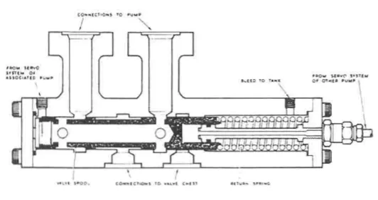
The servo-operated automatic change-over valves are held in the bypass condition by a spring while the associated pump is at rest. An idle pump must be bypassed, or it becomes a blockage in the circuit.
When a pump is started, the auxiliary pump pressure builds up, overcomes the spring, closes the bypass and connects the main pump to the hydraulic system. The sequence is automatic and it happens on the auxiliary pump's pressure alone — no operator action, no solenoid, no electrical signal.
Thus the main pump starts in the unloaded condition. Three consequences follow, and all three are deliberate:
- It cannot be motored when idle by cross pressure flow — the bypass is open, so the pressure in the live half of the circuit cannot drive the idle pump round backwards.
- Load is held off until the electric motor's high starting current has reduced to running level — the motor starts against no hydraulic load, which is what lets a relatively small motor start a large pump.
- When the pump is stopped, the spring returns the valve to the bypass condition — the change-over is automatic in both directions.
The spring end of the valve is connected to the constant pressure line, and, to obviate hydraulic locking, the spring chamber has a bleed line. The bleed line is the detail that stops the valve seizing: without it, the spring chamber would fill with oil at pressure and the valve would be locked in position by hydraulics rather than moved by them.
The valve chest
From the automatic change-over valves CO the main pump discharge passes to the pump isolating valves P1 and P2, and to the cylinders, through the locking valves LV.
These valves are incorporated in a group valve chest, so arranged as to provide cross-connections with the bypass valve BP, the relief valve RV and the emergency hand pump shut-off valves HP, with appropriate non-return valves NR.
Everything is gathered in one chest, which is why a steering gear's valve chest looks complicated and why its line-up has to be checked against the maker's diagram rather than reasoned out from first principles. The functions gathered there are:
| Valve | Function |
|---|---|
| P1, P2 | Pump isolating valves — isolate one power unit from the circuit |
| LV | Locking valves — lock the rudder by trapping oil in the cylinders |
| BP | Bypass valve — lets the two sides of the system connect, so the rudder can move freely |
| RV | Relief valve — the shock relief (see Chapter 11) |
| HP | Emergency hand pump shut-off valves — isolate the hand pump when it is not in use |
| NR | Non-return valves — enforce the direction of flow through the chest |
4. One pump or two
In open water it is usual to have one power unit in use. If quicker response is required from the gear, two units may be run simultaneously to double the oil flow and increase the speed of operation.
That is the whole purpose of the second unit in normal service: not redundancy, but speed. On a large ship in restricted water, running both pumps halves the time taken to put the rudder over, and that is worth having. In open water the second unit is a standby and nothing more.
The gear is controlled from the bridge through the control box, with a local means of control in the steering gear compartment as well. Both are described in Chapter 7, and the emergency use of the local control in Chapter 8.
5. The four-ram gear
The four-ram gear exists to give the redundancy the rules require (Chapter 1) without the complication of a second steering gear. It has twice as many cylinders as it needs, so that half of them can be isolated and the ship can still steer.
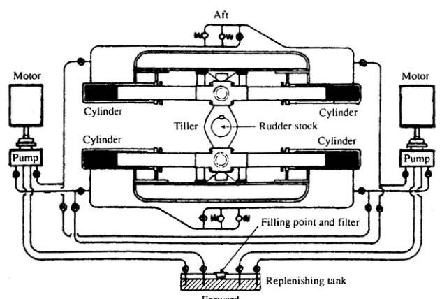
The drawing of a four-ram gear shows the Rapson slides, the combined guide and brace arrangement previously described, and the control box with its connecting link from the rudder stock. A second link from the stock to the rudder angle indicator transmitter is also shown. The rudder angle indicator is driven directly from the stock, not from the control system, which is what makes it a true indication of where the rudder actually is.
The hydraulic circuit incorporates an arrangement of stop and bypass valves in the chest VC, which enable the gear to be operated on all four or on any two adjacent cylinders but not with two diagonally disposed cylinders.
The prohibition on diagonal pairs is a piece of geometry, and it is worth understanding. The four cylinders act on a double-arm tiller, two on each arm. Isolating one cylinder on each side would leave an unbalanced arrangement — one arm being pushed and the other being pushed unevenly — and the tiller would be loaded in a way it was not designed for. So the rule is: any two adjacent cylinders, never a diagonal pair.
Inactive cylinders are isolated from the pumps by valves, while the bypass valves connecting them are opened to permit free flow of idle fluid. An isolated cylinder that was not bypassed would be a sealed volume of oil that the moving ram would have to displace — so the ram in it could not move, and the tiller could not turn. The bypass is what lets an isolated cylinder's ram move freely as a passenger.
Either or both duplicate independent power units may be employed with any usable combination of cylinders. The power units and the cylinder combinations are independent choices.
The torque available from two cylinders is only one-half of that from four, even when both power units are working, though the speed of operation will be increased if both are used. That is the trade the gear makes when it goes onto two cylinders: half the torque, but the same or better speed. Half the torque means half the rudder angle at full speed, or the full rudder angle at reduced speed — which is the basis of the automatic split system's behaviour described in Chapter 11.
The four-ram valve chest
The mechanical arrangement of the control gear and the basic hydraulic system, in all but their layout, are identical with the two-ram gear already described. The valve chest, however, must cater for four cylinders in all useful combinations. That means:
- four cylinder isolating valves, C1 to C4, and
- four bypass valves, B1 to B4.
The emergency hand pump arrangement, its directional control valve, the main system relief and the locking valves remain unchanged, as do the remote, local and emergency control arrangements. Only the cylinder isolation grows with the number of cylinders; everything else is the same.
Normally, the pump and the four cylinder isolating valves P1, P2 and C1 to C4, and the rudder locking valves LV, are open. The bypass valves B1 to B4 and the emergency hand pump isolating valves HP are closed. That is the running line-up: all four cylinders live, no bypasses open, hand pump isolated.
Power units may be brought into action or shut down by starting or stopping the associated motors — the automatic change-over valve does the rest, as described in section 3.
Changing from four rams to two
To change from four-ram to two-ram working, it is only necessary to make two cylinders inoperative by closing their isolating valves C1 to C4 and opening the bypass valves between them.
The worked example from the manual is the clearest way to state it: to steer on cylinders 1 and 3, valves C2 and C4 are closed and B2 and B4 are opened, so that cylinders 2 and 4 are isolated from the main hydraulic system and the oil in them is free to flow from one to the other.
The cylinder isolating valves and the bypass valves are shown as separate items in the diagram, but each pair may be combined as a double-seating valve, so that as any cylinder is isolated from the main hydraulic system it is automatically opened to a bypass manifold and to the other inoperative cylinder. That is the better arrangement, because it removes the possibility of isolating a cylinder and forgetting to bypass it — a mistake that would lock the gear solid.
The alternative valve arrangement
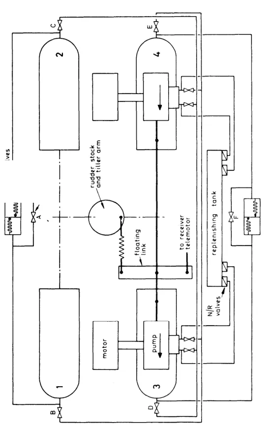
Another four-ram gear — the Hastie type — uses a valve arrangement that gives only three combinations instead of five:
- All four cylinders in operation.
- Cylinders 1 and 2 operational, with valves B, C and F open and A, D and E closed.
- Cylinders 3 and 4 operational, with valves A, D and E open and B, C and F closed.
The restriction to two fixed pairs rather than any adjacent pair is a simplification of the valve chest: it does the job the rules require with fewer valves, at the cost of flexibility. The hunting gear arrangement is similar to the two-ram system, and two pumps are normally employed.
6. The control valve block
A control valve block is a specific arrangement worth knowing, because it is a common way of gathering the valves and it illustrates how the pieces fit together.
Rudder locking valves on all cylinders are open except in cases of emergency.
The main valve block contains three groups of valves:
- Two rudder shock (relief) valves.
- Four pump isolating valves — two valves for each pump, A and B.
- Four combined ram cylinder isolating and bypass valves, connecting to each cylinder.
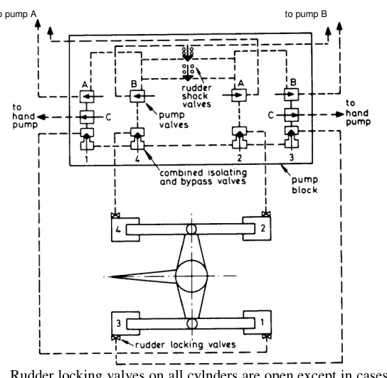
When a pump is not in use it is prevented from motoring and relieved of a starting load by a spring loaded discharge valve. This valve is kept in a bypass position until the pump is started up and its discharge pressure is sufficient to move the valve. The bypass connection is then automatically closed and the isolating connection opened, by valve movement, so connecting the pump hydraulically to the steering gear.
An alternative is to use a centrifugal coupling between motor and pump, whose pawls open out when running but when stopped the pawls engage a ratchet so locking against rotation. That is the non-reverse locking gear described in Chapter 5.
Under normal conditions either pump with four rams is in use, and to bring in the other pump only requires the operation of the starter. The four pump valves marked ABAB are open and the two hand pump valves marked CC are closed.
For emergency conditions with the pumps shut down, the four pump valves are closed and the two hand pump valves opened. That is the whole of the changeover to hand pumping: shut the pumps off the circuit, bring the hand pump on.
7. The replenishing system
The main system loses oil continuously — through pump leakage, past seals, and through the small internal leaks that every hydraulic system has. The replenishing system is what keeps it full.
Each pump has suction connections through non-return valves from the replenishing tank. The non-return valves let the pump draw make-up oil from the tank but do not let system oil flow back into it.
Losses of oil from the system are automatically made up from this reserve of oil.
A certain amount of leakage occurs in the pump, and this oil is drained to the replenishing tank.
Where an overhead tank is fitted — as on the V.S.G. pump installations — the oil is caused to flow from the pump casing by a centrifugal action produced by rotation of the cylinder block. Other oil flowing back into the pump gives a cooling action.
The centrifugal drainage detail is a neat piece of engineering: the pump's own rotation throws the leaked oil out of the casing into the overhead tank, and the returning oil cools the pump on its way through. The tank being overhead is what makes the drainage work by gravity, and it is why the level in that tank is one of the routine checks in Chapter 9.
8. What the ram type gear gives you
The ram type gear is the most common steering gear on merchant ships, and the reasons are worth stating plainly.
It is flexible. The torque can be increased by increasing the pressure, the ram area or the leverage — three separate variables, each of which can be adjusted within wide limits. A vane gear has no such freedom (see Chapter 6).
It is adaptable to mechanical alternatives. If the hydraulics fail entirely, a ram gear can be operated by hand pumping, by a hand pinion, or by relieving tackles rigged to the tiller. The ram and tiller are simple mechanical parts and anything that can push a ram can operate the gear.
It duplicates naturally. Two pumps, four cylinders and a valve chest give a gear that satisfies the single-failure rule without a second gear being fitted.
Its weaknesses are known and manageable. The hydraulic system can lose its oil, and the gear can then be smashed by the rudder swinging in a seaway. That failure, and everything that has been done about it, is the subject of Chapter 11.