
Hydraulic Drives for Deck Machinery — Fluid, Pumps and Circuits
Hydraulic power is the other half of the deck machinery story, and it is the drive of choice wherever the machinery is exposed, remote from the engine room, or sitting in a hazardous area.
Key Principles at a Glance 5 points
- Hydraulic power lets a constant-speed a.c. induction motor — the cheapest and most robust machine available — give infinitely variable output at the winch.
- Hydraulic power is intrinsically safe, which is what makes it the natural choice on tankers and gas carriers where an electric motor in the wrong place is a hazard.
- The oil is the working part of the machine as well as the lubricant: oxidation, water and metal wear all end in the jamming of valves with fine operating clearance.
- Water enters through shaft seals, by condensation on reservoir tank surfaces open to atmosphere, and when topping up — which is why a tank should never have cold hull plating as one wall.
- Variable delivery pump output can be controlled to give full flow in either direction and varied from maximum down to zero, so operational control valves are not required.
1. Why hydraulics on deck
In a hydraulic system the oil is the working part of the machine as well as the lubricant. Clean oil is not a refinement — it is the difference between a system that works for years and one that jams valves and wears itself out. Everything else in this chapter is secondary to that.
Hydraulic systems provide a means of distributing power and of obtaining it from a constant speed and constant direction drive such as an a.c. electric motor. The oil pressure can be used to provide variable speed drives through hydraulic motors and power for actuating devices.
Three properties make hydraulics attractive for deck machinery in particular:
- The drive motor is a constant speed a.c. induction motor, which is the cheapest and most robust machine available, while the output at the winch is infinitely variable.
- Hydraulic power is intrinsically safe, which is what makes it the natural choice on tankers and gas carriers where an electric motor in the wrong place is a hazard.
- Remote control of valves comes free with the same fluid, which is why hatch covers and watertight doors are operated hydraulically as well.
Hydraulic power is used extensively for deck machinery and remote control of valves.
2. The three essential components
The three essential components for a hydraulic circuit are:
- the hydraulic fluid, held in a reservoir tank,
- a pump to force the liquid through the system, and
- a motor or cylinder actuator to convert the energy of the moving liquid into a working rotary or linear mechanical force.
Valves to control liquid flow and pressure are required by some systems.
3. The hydraulic fluid
Water was the original hydraulic fluid and is still used for heavy duty such as the operation of lock gates or moving bridges. Its disadvantages are that it promotes rusting and other forms of corrosion, it is not a good lubricant, and it has a limited temperature range.
Hydraulic oils may be straight mineral or special additive oils. The properties of these, enhanced by additives, include oxidation stability, film strength, rust prevention, foam resistance, demulsibility and anti-wear characteristics, to enable the fluid to stand up to the higher operating temperatures and pressures of modern systems. Pour point depressants are used to prevent freezing in low temperature conditions.
Other fluids used in hydraulic systems may be synthetics or emulsions. Emulsions have been used in systems such as the telemotor, where force is applied and received by pistons. Oils are preferred for systems using rotating pumps and motors, where good lubrication is essential.
In an emergency where short term expediency is the criterion, any thin oil could be used in a system.
4. Deterioration of the oil
Hydraulic fluids which are basically mineral oils will degenerate very slowly over time due to oxidation. The factors which encourage oxidation are the heating and agitation of the oil in the presence of air and metal, particularly copper. The process is accelerated by:
- overheating, and
- contamination with products of corrosion or the presence of metal wear particles.
Oxidation products, both soluble and insoluble, increase the oil's viscosity and cause sludge to be deposited. Oxidation also tends to encourage the formation of emulsions with any water from leakage or condensation, and the acidic products of oxidation will cause corrosion in the system.
5. Contamination of the oil
Water promotes rusting of steel and must be excluded from hydraulic systems. Rust can be detached and, when carried around a circuit, can cause the jamming of those valves with fine operating clearance, as well as hastening deterioration of the oil.
There are three routes by which water gets in:
- Sea water can enter through the shaft seals of deck machinery and via system coolers.
- Condensation on the cold surfaces of reservoir tanks which are open to the atmosphere is a common source of contamination by water. This is why tanks should not be constructed such that cold hull plating forms one wall.
- Water can be carried in with the oil when topping up.
Metal wear is inevitable, and fine filters are installed to remove these and corrosion particles together with any other grit or dirt that finds its way into the system. Care is necessary with hoses, funnels and oil containers used for filling and topping up reservoir tanks, to ensure that they are clean.
The consequences of letting particles through are cumulative: fine metal wear particles can act as abrasives causing further wear, and all particles could cause blocking of small passages or the jamming of valves.
6. Fixed delivery pumps
Pump and motor systems are used for powering deck machinery such as winches and windlasses. Pump and actuating cylinders are normally employed for hatch covers. One or more pumps will be used to supply the volume of fluid at the pressure required to operate one or more motors.
Pumps may be classified into two groups:
- those with a fixed delivery when running at a given speed, and
- those with a variable delivery at a given speed.
Fixed delivery pumps can have their constant output bypassed via control valves until required, or the output can be matched to requirements by incorporating a relief/accumulator and then stopping and starting, varying speed, or connecting a variable delivery pump in parallel.
Gear and lobe pumps. Constant output pumps of the gear or lobe type are precision made to provide high pressure with minimum back leakage. A gear pump operates on the principle that as the gears revolve, fluid is carried around the outside between the gear teeth and the housing from the suction to the discharge side of the pump. Fluid from the discharge side is prevented from returning to the intake side by the close meshing of the two gears and the small clearances between the gears and housing. At the discharge side the fluid is discharged partly by centrifugal effect and partly by being forced from between the teeth as they mesh. Gear pumps may be of the conventional kind or of the type with meshing internal and external gears; lobe pumps are a variation of the latter.
Axial cylinder pumps can be made to deliver a fixed output by setting the swash plate for continuous full stroke operation.
7. Variable delivery pumps
Variable delivery pumps are used in hydraulic installations as the means of regulating pump output to suit demand. Variable delivery pump output can be controlled to give full flow in either direction, and volume output can be varied from maximum down to zero.
Steering gears are controlled directly by varying the pump output, and swash plate pumps are used to supply a range of hydraulic deck machinery. Automatic stroke control can be used to adjust the output.
8. Constant delivery pump systems
For general hydraulic systems where the pump delivers a constant volume of oil, speed control of the hydraulic motor can be obtained by delivering the required amount of oil to the motor through a control valve and diverting the remainder through a bypass to the pump suction.
The pump discharge pressure is determined by the load. Speed and direction of rotation are controlled by a lever operated balanced spool valve.
Where a hydraulic steering gear is fitted with a constant volume or fixed output pump, the control valve arrangement either delivers full pump output to the gear or bypasses pump output completely, and system pressure rises sharply when oil is channelled to the gear.
9. The unit type circuit — the Norwinch example
Many of the hydraulic systems fitted to deck machinery are of the 'unit' type, with one pump driving one motor. The Norwinch single hydraulic drive is the standard illustration of the arrangement.
The pump is of the vane type, consisting of a slightly elliptical case with a cylindrical rotor. The rotor has radial slots containing closely fitting rectangular vanes which are forced out against the casing by centrifugal effect and oil pressure. As the rotor turns, the expanding and contracting clearance between it and the casing produces a pumping action. Both mechanical and magnetic filters and a relief valve are provided, and the expansion tank contains a reserve of oil.
The motor is also of the vane type, with vanes mounted in a cylindrical rotor working in a housing which incorporates two pressure chambers. When the motor is required to exert maximum torque, oil flow from the pump is directed into both chambers. For lighter loads an operating lever is actuated to direct the full flow to only one of the pressure chambers. This gives two variable speed ranges.
The system shown is for mooring winches which are self-tensioning.
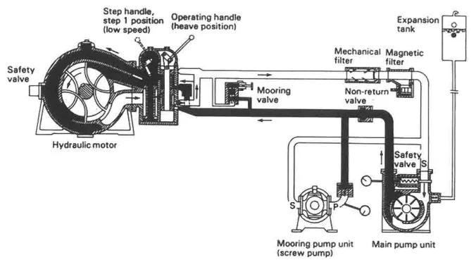
How the circuit behaves when the machine is idle. Pumps for installations such as this run at constant speed and are driven by an electric motor or directly by a prime mover. With the pump running there is a continuous flow of oil through the system whether the motor is in operation or not. When the winch is not in use the oil merely passes through the operating valve, bypassing the hydromotor and returning to the pump. Oil pressure is negligible when the hydromotor is idle, reducing the power required to a minimum. The oil in the pipelines to and from the motor always flows in the same direction; it is at the motor controls that the flow direction can be reversed to change the rotation of the winch.
10. Ring main systems
There are great advantages to be gained by the use of a ring main system rather than a series of unit circuits. With a ring main, one centrally located hydraulic pump is able to cater for the needs of a number of auxiliaries which can work simultaneously or alternately at varying loads. Because the equipment powered from this central pumping installation need not be restricted to deck machinery or to one type of equipment, the system offers considerable savings on capital cost.
A centralised hydraulic system consisting of duplicated oil pumps — usually rotary reciprocating — accumulators, filters and an oil reservoir, fitted with pressure regulators which govern the pressure in different lines for different purposes, is an economic, reliable and safe power distribution system. Items that can be operated by such a system include submersible or line-shaft driven pumps from deck motors, and deck machinery — winches, windlass, cranes, derricks, hatch covers, ramps, watertight doors and bow thruster.
The main advantages of a centralised hydraulic system are smooth operation, infinitely variable speed control, self-lubrication, intrinsic safety — which makes it useful for hazardous cargoes — and centralisation for ease of control.
11. Variable displacement pump systems
The hydraulically operated steering gear with an axial piston (V.S.G. type) or radial piston (Hele-Shaw type) variable delivery pump is an example of a variable displacement pump system. The pump itself controls the liquid flow, so that operational control valves are not required. The pump is driven at constant speed by an a.c. induction motor; the pump and motor together are referred to in the regulations as a power unit.
A variable displacement system can be used for deck machinery such as windlasses, winches and capstans, and also for cargo pumps. The power unit for such a circuit may be an axial piston pump with swash plate control to maintain constant pressure in the system. To match the demand of the hydraulic motors being supplied, the swash plate control servo-motor monitors system pressure and automatically adjusts pump output to keep the pressure constant. Oil cooling is provided by conventional sea-water circulated, tube type heat exchangers.
12. System design
Careful system design and contamination control are required during manufacture and installation of equipment. The rules that follow from that are short and worth knowing:
- Keep the number of joints and pipes to a minimum, to reduce the possibility of leakage.
- Select materials that will produce the least quantity of contaminating particles in the system.
- Fit filters capable of taking out particles down to a specified size.
- Shaft glands or seals must prevent leakage of oil out of the machinery and must also keep contamination out, whether the plant is running or shut down.
- Interlock the pump and motor control levers so that they must be in the neutral position before the pump driving motor can be started, in order to avoid inadvertent running of unmanned machinery. This is the design answer to a real accident: a pump started with a control lever off centre puts an unmanned winch or hatch cover into motion.
- Set the pressure relief valves between 30 and 50 per cent in excess of rated full load pressures. That figure is the overload protection for the whole system.