
Four-Stroke Aux Engines — Layout to Lubrication
Why medium-speed trunk engines rule auxiliary power, and how the MAN vee masters residual fuel.
Key Principles at a Glance 5 points
- Slow (to 300 rpm) propels directly; medium (300–900) generates and gears; high (above 900) drives vehicles — headroom and placement pick the winner.
- Diesel-electric frees engines from shaft lines: anywhere they fit, at constant efficient speed, with 2,000+ kW per cylinder available.
- Heavy residual fuel in trunk engines is a heating-and-cleaning economy: 380 cSt burnable, 180 cSt the costed optimum.
- 105–118 kg/cm² peaks with ~17–20 bmep punish heads, liners, pistons and every bearing — thin-shell lead-bronze throughout, inertia outweighing gas load.
- Caged valves lift out whole, roto-caps fight deposits, tandem plungers stretch slow-steaming to 1:5, and rocker oil never meets fuel or water.
1. Speed Bands & Placement Logic
Each speed band has its duty:
Slow two-strokes
Turn propellers directly.
Medium-speed four-strokes
Generate power and gear down to shafts.
High-speeds
Drive road and yacht machinery.
Four-strokes win propulsion where headroom is tight — ferries, passenger ships — and where diesel-electric lets engines sit anywhere at steady efficient revs instead of in line with shafting.
Medium band runs 250–850 rpm with 2,000+ kW per cylinder at the top end, trading shorter maintenance intervals for power-to-weight no slow-speed can match.
2. Layout — Fixed Frame, Moving Heart
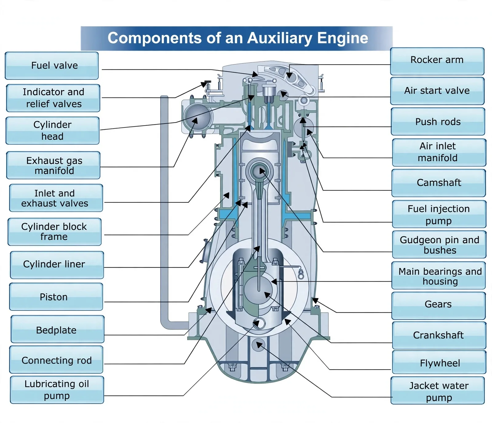
Fixed: bedplate, block frame, liner, head, manifolds, covers. Moving: piston, rod, crankshaft, flywheel, gears, camshaft, pumps, valves. Learn the map below and every later component has an address:
3. MAN Vee — Residual Fuel by Design
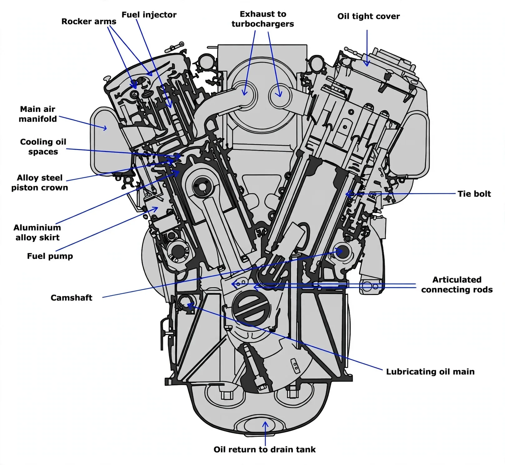
Trunk pistons burning residual fuel to 380 cSt (180 cSt the economic optimum after heating, cleaning and maintenance are costed) at 105–118 kg/cm² peaks and 17.3–19.7 bmep for 900–1100 bhp per cylinder at 400–430 rpm. Inertia out-loads gas pressure on bearings — short stiff crankshafts on thin-shell lead-bronze mains and crankpins throughout.
Details that matter:
- Thin-plate heads shedding heat to water with ribbed backs taking the load.
- Caged exhaust valves lifting out whole with seat cooling that starves vanadium/sodium deposits — Nimonic heads on Stellite seats, split-collet spindles, roto-cap rotation; full story in Aux Valves, Timing & Firing Order §1.
- Tandem different-diameter plungers stretching slow-steaming to 1:4–1:5 without slip clutches.
- Alloy crown on light skirt with cocktail-shaker under-crown oil.
- Fuel, water and rocker oil routed so they can never meet (VV 52/55 separation).
- Cased needle valves draining leaks overside of the crankcase.
4. Trunk Lubrication Circuit
Dry sump, independent pumps, filters, cooler: common rail to mains → crankshaft drillings to crankpins → rod passages to gudgeons and piston cooling, with branches to gears, cams, detuner, rockers, governor, servos and both turbochargers on shared SAE 30 detergent oil. Cylinder oil stays a separate mechanical system — and any head fuel or water leak that reaches rocker drains shows why the circuits must never mix.