Chain Drive & Camshaft — Timing Transmission
What the chain drives, how rollers and pins wear, and the inspection that catches a jumping chain early.
Key Principles at a Glance 5 points
- One chain times everything: exhaust-valve and fuel cams, lubricators, starting-air distributor and governor all hang off the crankshaft through it.
- Rollers roll on bushings, pins join the links — free rollers, free links, intact teeth and live lubrication are the whole inspection.
- Tensioning is automatic (tightening wheel plus load spring) with guide wheels and rubbing strips steadying the spans.
- Camshafts build in flanged sections on fitted bolts; cams sit shrunk, integral or keyed — and run at crank speed on two-strokes.
- Reversing method picks the drive: spur gears where cams shift bodily, chain where rollers shift on the cams.
1. One Chain Times Everything
Idea in one line: one loop from the crankshaft carries the engine's whole timetable — lose it and every timed event fails together.
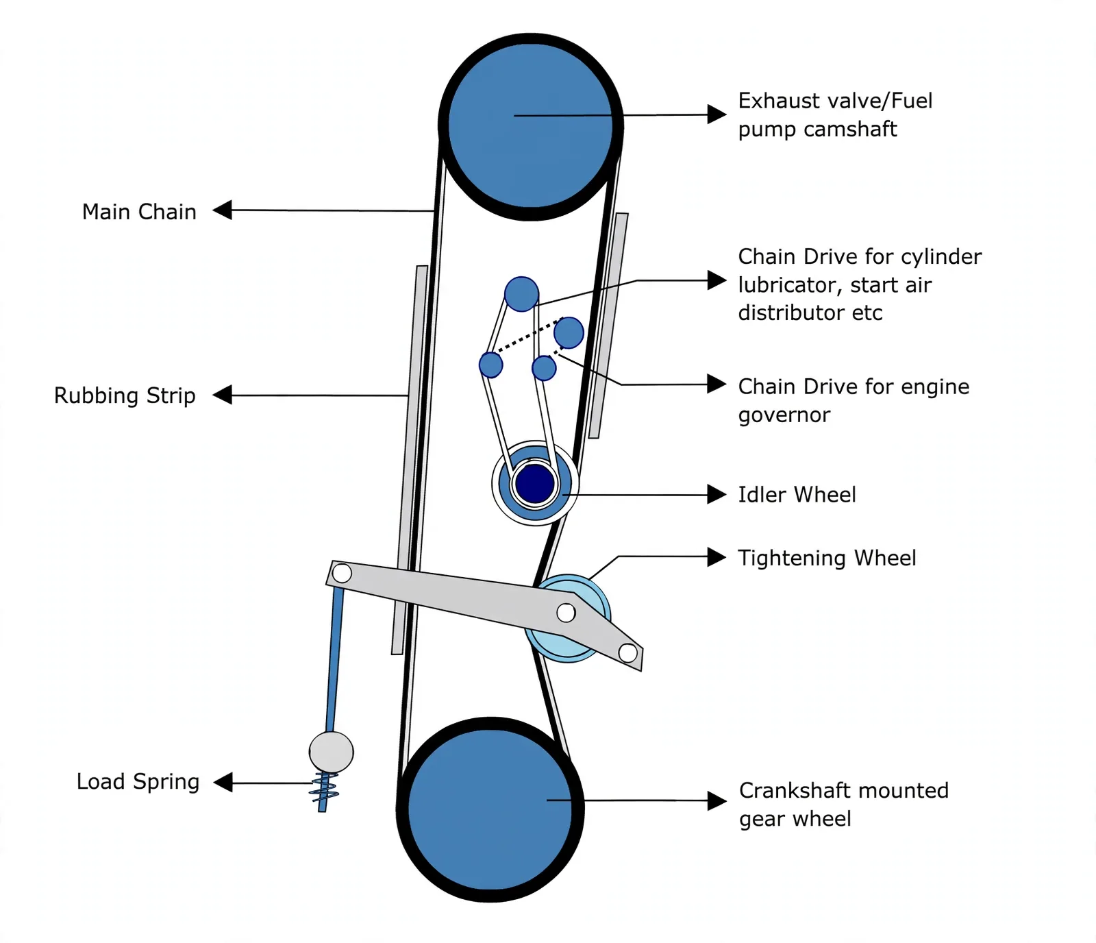
Exhaust-valve and fuel-pump camshaft, cylinder lubricators, starting-air distributor and governor are driven directly or indirectly from the crankshaft by gear train or chain. The drive is fitted at the aft end of the camshaft, which turns at crank speed on a two-stroke.
Timed by the loop
Fuel cams, exhaust cams, indicator-drive cams, lubricators, air distributor, governor — all take their moment from this one drive.
Two hardware answers
Gear trains with idlers and LO sprayers, or a roller chain over crankshaft and camshaft wheels with guide wheels and tensioning — same job, different reversing fit.
2. Construction & the Wear Inspection
Idea in one line: pins inside bushings inside rollers — every interface must stay free, fed with oil, and free of cracks.
Roller-links alternate with pin-links: each pin-link has two pins riveted between side plates, each roller-link has two rollers free on two bushings, and the pins sit inside the bushings of neighbouring roller-links. The loop runs over crankshaft and camshaft wheels with a spring-loaded tightening wheel taking up slack automatically.
| Check | What passes |
|---|---|
| Rollers and links | Wear within limits, every roller free, every link free on pins and bushings |
| Cracks and abrasion | No cracks, no abrasive wear on pins, bushings or side plates |
| Lubrication | Nozzle and spreader bolts tight, spray effective, no scuffing or galling from starvation |
| Guide-ways | Rubber-clad ways unworn and undisplaced |
| Sprockets | Teeth true against a profile gauge |
3. Camshaft — Sections Carrying Every Cam
Idea in one line: a shaft built in bolted sections, cams locked so timing cannot creep, driving everything that must happen on cue.
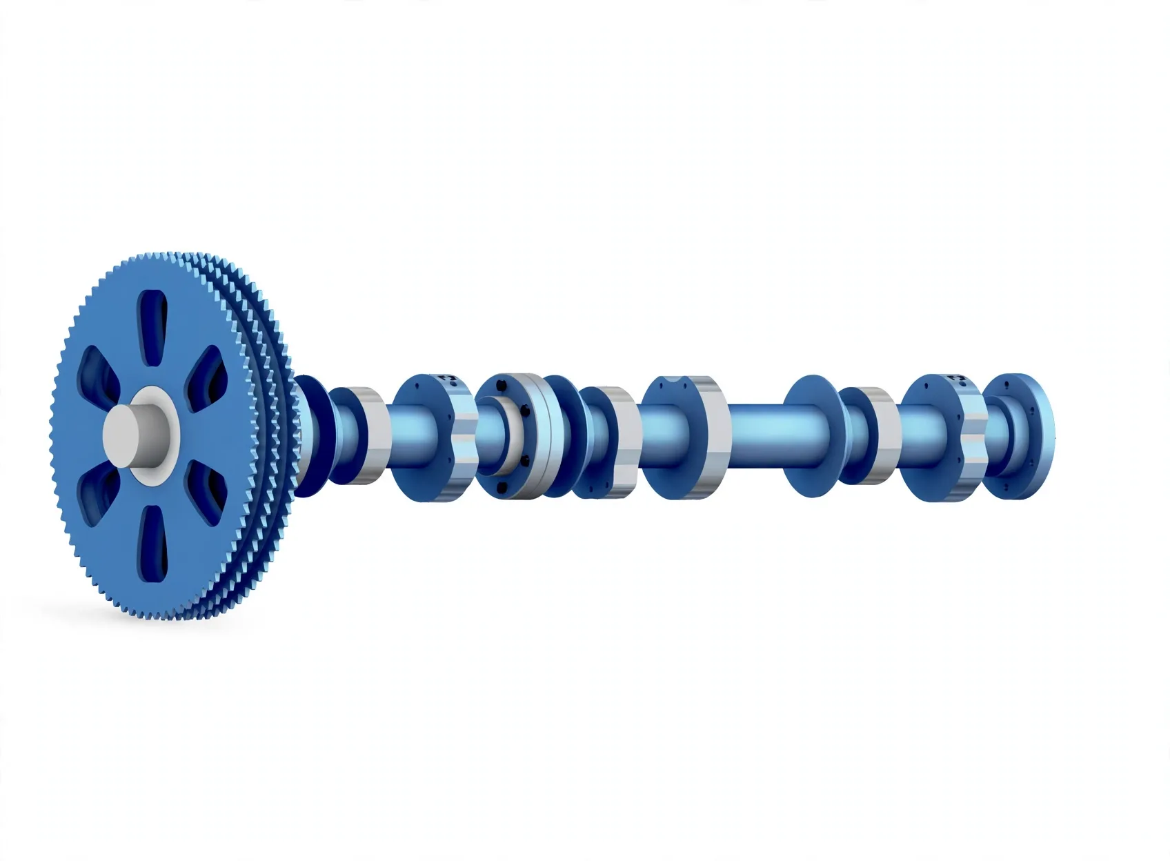
Camshaft sections join through flange couplings with fitted bolts and nuts and ride in a series of bearings. Fuel-pump, exhaust-valve and indicator-drive cams sit shrunk, integral or keyed for positive positioning; the far end works the cylinder lubricators and the starting-air distributor.
Sections, not one bar
Flanged lengths on fitted bolts — dismantle a section without scrapping the shaft.
Cams that cannot creep
Shrunk, integral or keyed seats hold fuel, exhaust and indicator cams exactly on time.
Reversing picks the drive
Axial or rotary camshaft displacement for reversing suits a spur-gear train; shifting cam rollers suits a chain wheel drive. Gear lubrication comes from LO sprayers off the main circuit.