
Troubleshooting Index
The pump is rarely the first thing that changed — find what changed, and the fault names itself.
Key Principles at a Glance 5 points
- Check suction pressure, discharge pressure, motor amperage and strainer differential pressure first — those four readings localise the fault to suction side, pump body or discharge side.
- Most pump faults onboard trace to one of four causes: a choked suction strainer, air ingress on the suction side, wear ring clearance gone, or misalignment.
- Low capacity with normal amperage points at worn wear rings; low capacity with high amperage points at something resisting rotation.
- Always ask both "what failed?" and "why did it fail?" — fixing only the first guarantees the fault returns.
- A gland that has gone from drop-by-drop leakage to a stream, or a bearing temperature climbing fast, means stop the pump now, not at the end of the watch.
1. How to Approach a Pump Fault
The four major problems faced are: loss of suction, failure to build up pressure, vibration, overheating and motor overload.
Before you touch anything, answer four questions:
Did it ever work? If not — installation or duty error, wrong rotation, wrong impeller.
What changed? Level, temperature, viscosity, valve position, process demand, recent work.
Is it the pump or the system? Check suction pressure and strainer first — this is where most faults are.
Is it getting liquid, and is it getting it clean?
The first four checks, every time:
- Suction pressure at the pump nozzle.
- Discharge pressure at the pump nozzle.
- Motor amperage against rated.
- Suction strainer differential pressure and suction valve position.
If those four are known, the fault is already localised to suction side, pump body, or discharge side.
2. Centrifugal Pump — Troubleshooting Table
| Symptom | Likely causes | Immediate action | Confirmation checks | Prevention |
|---|---|---|---|---|
| Pump does not deliver | Not primed; casing full of air/vapour; suction valve shut or partly closed; suction line clogged; suction strainer choked; lost prime; air leak on suction side; wrong direction of rotation | Stop; vent casing; re-prime; check suction valve and strainer; check rotation | Open vent — is water issuing? Check suction gauge; check strainer DP; check phase rotation | Prove priming procedure; keep strainer clean; log strainer DP; mark direction of rotation |
| Low capacity / drop in capacity | Worn parts — excessive wear ring clearance; impeller boxed up the wrong way; wrong rpm / driver fault; partly closed suction valve; obstruction in suction/discharge; air ingress; wrong impeller diameter; worn/eroded impeller | Check suction; open valves fully; check strainer; measure amperage | Discharge pressure vs design; compare with previous readings; strip and measure wear ring clearance | Record baseline performance; measure and log clearances at each overhaul; confirm impeller orientation before dismantling and before re-assembly |
| Failure to build up pressure | Loss of suction; air ingress; worn wear rings; impeller damage/erosion; cavitation; driver not reaching speed; relief/bypass passing | Stop and investigate suction side first | Suction gauge, discharge gauge, ammeter, rpm | Keep suction side tight; maintain wear rings |
| Loss of suction / will not pick up | Insufficient supply head; air leak in suction pipe (e.g. valve open on empty bilge); loss of priming facility; leaking shaft gland; suction strainer choked; vortexing at low tank level; low tank level; hot liquid (Hvp too high) | Stop; re-prime; check suction line and strainer; check level; check temperature | Prime and watch for air; soap-test suction joints; check NPSHa vs NPSHr | Maintain priming system; adequate submergence; keep suction side gas-tight; don't pump hotter than designed |
| Cavitation — crackling/gravel noise, erratic flow | NPSHa below NPSHr; suction restriction; liquid too hot or volatile; impeller speed excessive; strainer choked; air ingress; low tank level | Reduce flow (throttle discharge slightly) or reduce speed; then correct the root cause | Compare NPSHa with NPSHr curve; check suction temp and level; inspect impeller for damage | Design suction for adequate NPSHa + margin; keep strainers clean; control temperature |
| Excessive vibration | Loose coupling; loose impeller; damaged bearing; impeller imbalance; misalignment; bent shaft; cavitation; operating far from BEP (radial hydraulic side load); inadequate foundation; inadequately supported piping; multiple pumps operating in phase | Reduce to safe condition; stop if vibration severe | Vibration reading on bearing housings (vertical, horizontal, axial) and frequency analysis; check coupling and foundation bolts; check impeller for imbalance | Proper alignment; adequate foundation and pipe support; operate near BEP |
| Motor overload / high amperage | Excessive resistance to motion — imbalance, bent shaft, insufficient working clearances, damaged bearings, clogged impellers; operating at low head / high throughput; two-phase supply; wrong rotation; excessive viscosity; discharge line blocked; running far right of BEP | Stop; check amperage on all phases; check rotation; check discharge line and strainer | Compare amps with nameplate; check discharge pressure; check bearing temperature | Keep impeller and clearances in good order; correct alignment; operate near BEP |
| Overheating of casing / pump | At low capacities, the power supplied to the pump is no longer useful work — it becomes heat; internal recirculation; insufficient cooling; bearing overheating; gland too tight; discharge restricted or closed | Increase flow or stop the pump | Casing temperature; flow rate vs minimum continuous flow | Fit and use a minimum-flow recirculation line; avoid prolonged low-flow running |
| Bearing overheating | Grease/oil level too low or improper grade; dirt in bearing or moisture; bearing too tight; oil seals fitted too closely on shaft; misalignment | Check lubrication first; check alignment | Bearing temperature; oil condition (water/emulsion); vibration; hand-feel after stop | Correct lubrication schedule and grade; keep seals in order; align properly |
| Gland/seal leaking excessively | Worn packing; worn shaft or sleeve; worn stuffing box; wrong size packing; worn O-ring seal; mechanical seal failure; shaft fretting under the seal; misalignment | Adjust gland (packed pumps); renew packing/seal | Measure packing size: (stuffing box bore − shaft dia.) ÷ 2; check shaft trueness with a dial gauge | Correct repacking technique; correct seal installation; check alignment whenever shaft/impeller/bearings are replaced |
| Gland running hot / no leakage | Gland over-tightened; packing dried out; wrong packing; shaft sleeve worn | Slacken gland to give drop-by-drop leakage; renew packing if at stage 3/4 | Check leakage rate; check sleeve surface | Maintain drop-by-drop leakage; renew packing at stage 3 |
| Water hammer / shock in discharge line | Closing discharge too fast; non-return valve defective; air in line after a stop; pump started with air in discharge; rapid valve operation | Slow down valve operation; vent the line | Check NRV; listen at the valve | Slow valve operation; vent before starting; maintain NRVs |
| Seal fails repeatedly / premature seal failure | Shaft fretting under the seal (misalignment problem); O-ring nicks/cuts at installation; O-ring sticking to shaft (crystallising liquids, solids, oversized shaft/sleeve); springs clogged and jammed with solids; discharge bypass line blasting seal with solids; ozone attack on Buna-N O-rings; incorrect installation dimension | Strip and examine the seal faces and O-ring | Look for: fretting groove on shaft, nicked O-ring, crystallised product, jammed springs | Fit the correct seal for the duty; convert to suction bypass not discharge bypass in slurry service; store O-rings away from fluorescent lighting and electric motors |
| Pump runs but flow/pressure fluctuates | Air ingress; cavitation; fluctuating suction level; defective NRV; entrained gas; level control hunting | Check suction side; check level control | Suction pressure trend; vent the casing | Gas-tight suction; level control tuning |
| Excessive erosion of impeller/casing | Abrasives in the pumped liquid; high fluid velocity; turbulence; throttling; cavitation | Assess wear; renew components as needed | Inspect impeller and casing on dismantling | Fit abrasion-resistant or non-metallic pumps; reduce velocity; avoid throttling; provide water service to shaft seal area |
The impeller inspection points
The impeller should be visually inspected for wear, erosion and cavitation damage. The impeller should not be excessively worn at any point, either due to contact or due to corrosion.
The vanes at the eye and at the discharge are the trouble spots.
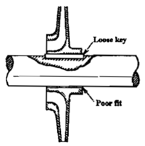
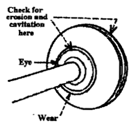
Diffuser blades which have worn at the tips need to be dressed up, to avoid stress raisers.
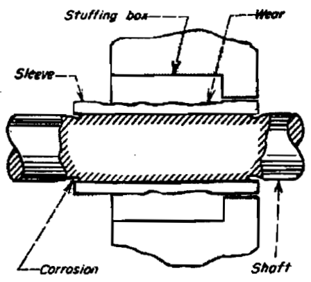
The shaft needs to be checked, especially the sleeve in way of the stuffing box, which is susceptible to damage from packing that has been excessively tightened.
3. Reciprocating Pump — Troubleshooting Table
| Symptom | Likely causes | Immediate action | Confirmation checks | Prevention |
|---|---|---|---|---|
| Low volumetric efficiency — fails to deliver rated capacity and pressure | Air or vapour pocket in inlet line; capacity of charge pump less than power pump; air/vapour trapped in or above inlet manifold; air leak in liquid supply piping; loose bolts in pump inlet manifold; air or gases entrained in liquid; foreign object holding inlet or discharge valve open; incorrect drive ratio; loose belts; incorrect motor/engine speed; loose valve covers or cylinder head; worn valves and seats; safety relief valve partially open or not holding pressure; worn liners, piston rings or plungers; bypass valve open or not holding pressure; blown liner gasket; NPSH not sufficient; liquid bypassing internally; foreign object blocking liquid passage; vortex in supply tank; insufficient power from motor | Check valves first; check relief valve; check bypass; check NPSH | Valve lift and seating; relief valve setting; liner and ring condition; amperage | Maintain valves and rings in good order; correct relief setting; correct NPSH |
| NPSH too low | Inlet line partially clogged; liquid vapour pressure too high; liquid pumping temperature too high; restricted inlet pipe fittings; inlet line too long; too many pipe fittings; too small inlet line; too low static inlet head; too low atmospheric pressure | Clean strainer; check temperature; check level | Compare NPSHa with NPSHr | Adequate suction design; keep strainer clean; control temperature |
| Liquid not delivered | Pump not primed; air/vapour pocket in inlet line; clogged inlet line; all inlet valves propped open; all discharge valves propped open; loose bolts in pump inlet manifold; too high valve velocities | Check valves — are they seating? | Inspect valve chest | Maintain valves; keep strainer clean |
| Cavitation | NPSH too low; liquid not delivered to pump inlet connection; excessive stuffing box leakage; NPSH too high | As above | As above | As above |
| Leak at cylinder head or valve cover | Over recommended pressure; loose cylinder head/valve cover; damaged gasket/O-ring | Stop; reduce pressure; retighten/renew joint | Check discharge pressure against rating | Correct torque; correct gaskets; don't over-pressure |
| Water in crankcase oil | Water condensation; worn seals; clogged air breather(s); worn crankcase packing; loose covers | Change oil; investigate source | Oil condition; breather; seals | Maintain breathers and seals |
| Oil leakage from crankcase | Oil level/temperature too high; worn seals; worn crankcase packing; loose crankcase cover | Correct level; renew seals | Oil level; seal condition | Correct oil level and grade |
| Excessive heat in power end | Pump running backward or RPM too low; insufficient oil in power end; excessive oil in power end; incorrect oil viscosity; operating above recommended pressure; main bearings too tight; drive misaligned; belts too tight; pump RPM too low; inadequate ventilation; liquid end packing adjusted too tight | Stop; check oil level and grade; check alignment; check direction | Oil level; alignment; direction of rotation | Correct lubrication; correct alignment; correct packing adjustment |
| Pump overloads driver | Pump RPM too high; low voltage or other electrical trouble; trouble with engine/turbine/gear reducer; excessive discharge line pressure; clogged discharge line; closed/throttled valve in discharge line; incorrect plunger/piston size; improper bypass conditions; over-tightened stuffing box glands; insufficient cooling | Stop; open discharge; check bypass; check electrical supply | Ammeter; discharge pressure; relief valve | Correct duty selection; correct relief setting; correct gland adjustment |
| Stuffing box leakage | Worn packing; worn rods or plunger; worn stuffing boxes; wrong size packing; worn O-ring seal (replaceable boxes) | Renew packing; check rod condition | Packing size measurement; rod wear | Correct packing size and grade; correct adjustment |
| Discharge valve (one or more) stuck open | Foreign object; worn valve/seat; broken spring | Strip and clean | Valve lift and seat | Strainer; regular valve inspection |
| Stud failure | Excessive discharge pressure; improper torquing of nuts; shock overload caused by pump cavitation | Renew studs; correct torque; fix cavitation | Torque values; discharge pressure | Correct torque; eliminate cavitation |
| Excessive valve noise | Broken or weak valve spring; pump cavitation; air leak in inlet piping or loose bolts in inlet manifold; air trapped above inlet valve | Check springs; check suction tightness | Spring condition; suction leak test | Maintain springs; gas-tight suction |
| Inlet or discharge line vibration | Piping inadequately supported; inlet line too long or too small in diameter; too many bends in inlet line; multiple pump installations operating in phase; obstruction under valve(s); packing worn; operating above recommended pressure or RPM; low NPSHA | Improve support; check air vessel | Pipe supports; air vessel condition | Adequate pipe support; correct line sizing; air vessels in order |
| Noisy operation — differentiate liquid knock from mechanical knock | Liquid knock: pump cavitation; liquid knock; air leak in inlet piping; loose bolts in inlet manifold; hydraulic noise in liquid end. Mechanical knock: piston or plunger loose; valve noise amplified through power end; loose or worn crosshead pins and bushings; loose connecting rod cap bolt; worn connecting rod bearings; worn crosshead; main bearing end play excessive; worn gears or chains; gears or chains out of line; pump running backward; partial loss of prime; shocks in piping system; water in power end crankcase; poorly supported piping, abrupt turns, misaligned piping, pipe size too small | Establish which — liquid or mechanical — before stripping | Listen with a stethoscope; check oil for water; check alignment | Correct maintenance of running gear; correct suction conditions |
Reciprocating pump maintenance — what actually wears
Because there are many moving parts, wear and tear is high. The items requiring attention:
- Piston rings — always in direct contact with the liner body, so they wear a lot. Change from time to time.
- Valves — must be looked after, or leakage develops across them.
- Gland packing — where the shaft emerges, maintained to control leakage.
- Coupling or crosshead — where the piston gets linear motion, checked for misalignment and wear.
This is exactly why reciprocating pumps are limited in use onboard: they are used where low suction and high-pressure head are required.
4. Gear and Screw Pump — Troubleshooting
| Symptom | Likely causes | Immediate action | Confirmation checks | Prevention |
|---|---|---|---|---|
| Loss of capacity | Worn gears/screws; excessive backlash; worn bushings/bearings; worn casing liner/sleeve; relief valve passing; air ingress; high slip due to increased clearances | Check relief valve; measure backlash; inspect bushings | Dial indicator backlash; feeler gauge; bushing clearance | Measure and record backlash at every overhaul; renew gears as a set when beyond max |
| Excessive noise | Worn or damaged bearings/bushings (crude noise when turned by hand); gear wear; air in the liquid; cavitation on the suction side | Strip and inspect | Turn by hand and listen; check backlash | Maintain alignment; keep suction gas-tight |
| Overheating / seizure | Insufficient clearance; timing gears out of adjustment (screw pumps); lack of liquid (dry running); excessive discharge pressure | Stop immediately | Check relief valve; check for dry running | Never run dry; correct timing gear clearance; correct relief setting |
| Oil seal leakage | Worn or damaged seal lips | Renew seal | Inspect lips | Always renew the oil seal whenever the pump is dismantled |
| Relief valve lifting continuously | Discharge valve closed; blockage; relief set too low | Open discharge; clear blockage; check setting | Discharge pressure; valve position | Correct relief setting; correct valve line-up |
| Vibration | Misalignment; worn coupling; worn bearings; air in liquid | Check alignment and coupling | Dial gauge alignment; coupling condition | Correct alignment; correct shims retained and reused in order |
Gear pump overhaul — the checks that matter
Check the backlash clearance — if more than the permissible limit given in the manual, the gears need to be changed. Record the backlash clearances for future reference.
Check the bushings/bearings — if worn out, or ball bearings produce a crude noise when turned by hand, they need changing.
Check the oil seal — if lips are worn or slightly damaged, renew. It is always good to change the oil seal whenever the pump is dismantled.
Clean the joint seating places on both main shell and back cover; replace if damaged.
On re-assembly, hold the back cover correctly in place while the gear shafts enter the bushings.
Turn the drive shaft by hand — it should turn without any wobbling.
Refit with a new joint; refit the drain plug.
Re-install on a cleaned foundation with the correct shims in place; move the motor so both flanges are close; check for any glaring misalignment.
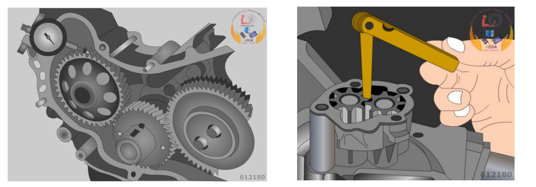
Standard gear backlash: 0.02 to 0.15 mm (0.0008 to 0.0060 in.)
Maximum gear backlash: 0.20 mm (0.0079 in.)
If the backlash is greater than the maximum, replace the gears as a set — change both.
5. The Five-Step Fault-Finding Method
Observe — pressure, temperature, amperage, noise, vibration, leakage. Compare with the pump's own baseline.
Localise — suction side, pump body, or discharge side? The four checks in §1 answer this.
Hypothesise — pick the two or three most likely causes from the tables above.
Confirm — do not strip the pump to test a hypothesis that a gauge can answer. A suction gauge, a strainer DP, and an ammeter eliminate half the table.
Correct the cause, not the symptom — if a mechanical seal has failed because of shaft misalignment, replacing the seal will not fix it.
The four most common real-world causes
In practice, most pump faults onboard trace to one of these:
Suction strainer choked
Low flow, low pressure, high vacuum at suction, possible cavitation.
Air ingress on suction side
Loss of prime, fluctuating flow, noisy running.
Wear ring clearance gone
Gradual loss of capacity and head with normal amperage.
Misalignment
Vibration, bearing failure, repeated seal failure, coupling wear.
When NOT to keep running
- Severe vibration or a sudden change in noise.
- Bearing temperature rising rapidly.
- Loss of suction that cannot be restored by venting.
- Any smell of burning or smoke from the motor.
- A gland that has gone from drop-by-drop leakage to a stream.
- Any sign of the pump running dry.
6. Failure Analysis Discipline
Keep a pump maintenance file. For every pump, record:
- Date and reason the pump came into the workshop ("Why is this pump in the shop?").
- Running hours since last overhaul.
- What was found — measured clearances, photographs of damage.
- What was replaced.
- What was measured after reassembly.
- What the pump was like when returned to service.
The two questions to ask on every strip-down:
- What failed? — the immediate mechanism.
- Why did it fail? — the root cause. Because if you only fix the first, it will fail again.
Reading the evidence
| Evidence | Most likely cause |
|---|---|
| Impeller vane metal removed in a honeycomb pattern at the eye/suction side | Cavitation |
| Wear ring and impeller boss heavily eroded, clearance grossly enlarged | Abrasive solids, or long-term wear |
| Impeller contact marks on one side only | Misalignment, bent shaft, or bearing failure |
| Fretting groove on the shaft under the mechanical seal | Seal misalignment / seal chamber face not perpendicular to shaft |
| O-ring nicked or cut | Damaged during installation over threads, keyways or steps |
| Seal springs clogged with solids | Slurry service with wrong seal design or wrong bypass arrangement |
| Packing hard, blackened and calcified, shaft sleeve deeply grooved | Packing run past stage 3 to stage 4 |
| Bearing blue/discoloured, grease carbonised | Under-lubrication, wrong grade, or overheating |
| Cracked casing at a flange or joint | Thermal shock, hydraulic shock, or over-torqued bolts |