
Normal Operation, Load Control, and Watchkeeping
Normal operation is not a fixed set of numbers — it is a dynamic balance held inside limits while the ship’s demand moves around it.
Key Principles at a Glance 8 points
- Three quantities are held inside their limits — steam pressure by firing rate, drum level by feedwater flow, steam temperature by attemperation and gas-side conditions. Everything else on the gauge board is evidence about how well those three are controlled.
- Read trends, not numbers. A level drifting steadily is a different problem from a level that is hunting.
- Swell and shrink mean the indicated level during a fast load change is not the quantity of water in the drum. Never make a large feedwater correction from a single rapidly changing indication.
- Single-element control follows level only; two-element adds steam flow as feed-forward; three-element adds feedwater flow to correct for blowdown, leaks and supply pressure changes.
- Correct atomisation first, then set the air-fuel ratio — opening the air to cover smoke hides the real fault while consumption and deposits continue.
- Soot is an insulator and a fire risk: blow on steady load with dry steam, and treat the fall in exit gas temperature as the measurable proof it worked.
- The trend predicts the failure: uptake temperature rising at constant load, firing rate rising for the same output, and feedwater flow rising at steady steam flow are all warnings.
- Never defeat a trip outside an approved test, and never run with an inoperable gauge glass, safety valve or alarm.
1. What normal operation actually is
Normal operation is not a fixed set of numbers on a gauge board. It is a dynamic balance in which three quantities are held inside their limits while the ship's steam demand changes around them:
- Steam pressure — held by the firing rate.
- Drum water level — held by the feedwater flow.
- Steam temperature — held by attemperation and gas-side conditions.
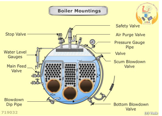
Every other instrument on the boiler is evidence about how well those three are being controlled. Uptake temperature tells you about heat transfer. Furnace pressure tells you about draught balance. Flue-gas oxygen tells you about combustion. None of them is a target in itself.
The operator's job is to recognise when the balance is drifting, and to correct it before it becomes a trip. That means reading trends, not just numbers.
2. The watchkeeping round
A boiler round is not a walk past the gauges. It is a structured inspection with a purpose: confirm each of the five flows, and look for the early signs of the faults in Topic 6.
2.1 Water level
What to do:
- Read both gauge glasses. They must agree.
- Blow through each glass at the required interval using the correct sequence.
- Compare the local reading against the remote indicator in the control room.
- Watch how the level is moving, not just where it is. A level that is drifting steadily is a different problem from a level that is hunting.
What to look for:
- Glasses disagreeing — a blocked steam or water passage, a wrong valve position, or a faulty glass. Confirm by blowing through each glass individually.
- Glass not refilling correctly after blow-through — a blocked passage. A glass that fills slowly, or fills only partly, is telling you something is obstructing it.
- Level hunting — control loop instability, or a genuine physical disturbance such as foaming.
- Level drifting in one direction — feed control not matching demand, or a leak.
A gauge glass is a direct indication, but it can be wrong. A remote transmitter is convenient, but it can be wrong. When they disagree, the direct reading takes priority — and then you find out which one is faulty.
2.2 Pressure and temperature
- Record steam pressure against the required value.
- Record steam temperature where superheated.
- Compare pressure with the saturation temperature, or the superheat margin.
- Watch the rate of change, not just the value. A pressure falling slowly over hours is a different situation from one falling quickly.
What to look for:
- Pressure falling at constant firing — the boiler is not generating what it was. Excess demand, a new leak, or a combustion problem.
- Pressure rising at constant firing — demand has fallen, or the pressure controller is not reducing firing correctly.
- Temperature rising at falling load — the classic low-steam-flow superheater problem.
- Temperature falling — attemperator passing, or superheater fouled with wet or dirty steam.
- Superheat margin disappearing — the steam is approaching saturation, which suggests wet steam.
2.3 Combustion and flame
- Look through the sight port at every round. Do not rely on the scanner alone.
- Check the flame's shape, colour, stability, and position.
- Confirm the flame scanner reads flame present.
- Look at the funnel smoke — or the camera view of it, where fitted.
- Check furnace pressure against its set point.
- Check flue-gas temperature before and after each heating surface where instruments are fitted.
What to look for:
- Flame lifting off the burner — insufficient fuel pressure, too much primary air, or a draught problem.
- Flame too long or smoky — poor atomisation, insufficient air, or fuel too cold.
- Flame impinging on a tube or the quarl — wrong burner position, wrong spray angle, or a damaged tip.
- Flame pulsating — draught instability, fuel pressure fluctuation, or water in the fuel.
- Furnace pressure drifting positive — gas path obstruction, damper problem, or fan fault.
- Rising uptake temperature — fouling, baffle damage, or wrong air-fuel ratio.
2.4 Fuel system
- Fuel pressure at the burner.
- Fuel temperature at the burner.
- Viscosity indication, or the temperature corresponding to the required viscosity for the current fuel.
- Differential pressure across filters.
- Fuel return flow, where fitted.
- Any sign of leakage at flanges, the heater, filters, or the burner carrier.
What to look for:
- Rising filter differential — filters choking. Change before the pressure at the burner falls.
- Temperature drifting from set point — heater control fault, steam supply problem, or a fuel grade change altering the required temperature.
- Pressure fluctuation — pump wear, air in the line, or a control valve hunting.
- Any leak on a hot fuel line — a fire risk, and on the high-pressure side of the burner, an immediate hazard. Isolate and repair.
2.5 Air system
- Forced-draught fan running, with normal current, vibration, and bearing temperature.
- Damper position matching the firing rate.
- Air register position correct for the burner in use.
- Air heater or air preheater conditions where fitted — differential pressure, temperature.
- Any abnormal noise from the fan, including surging or rubbing.
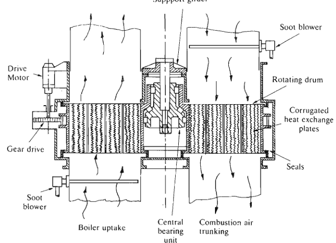
The rotary air heater sits in the uptake gas path with its rotating drum, corrugated heat-exchange elements, drive motor and soot blower. On rounds check the drive running, the differential pressure and temperatures across it, and that the soot blower is parked — a fouled or stalled heater raises exit gas temperature and starves the furnace of hot air.
What to look for:
- Fan current falling at constant damper position — the fan is moving less air, which suggests a blockage or a damped-up path.
- Fan surging — flow instability, usually at low flow or high resistance. Surging damages bearings and blades.
- Damper not matching the demand signal — actuator or linkage fault. This produces an air-fuel mismatch, and the burner management system may trip on airflow.
2.6 Feedwater system
- Feed pump running, with normal suction and discharge pressure.
- Standby pump available and proven.
- Feed control valve position and response.
- Feedwater temperature at the economiser inlet.
- Any leakage at pump glands, joints, or check valves.
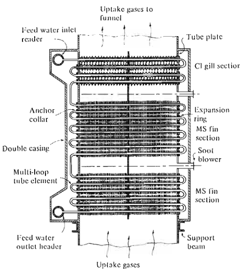
Feedwater picks up its final heating in the economiser before entering the drum. Watch the feedwater temperature at the economiser inlet and the gas temperature at its outlet: a falling feed temperature means a heater or deaerator fault upstream, and a rising gas outlet temperature means the economiser surface is fouled or steaming instead of heating water.
What to look for:
- Feed pump discharge pressure falling — pump wear, suction restriction, or cavitation. On hot condensate service, cavitation is a real risk if the suction is restricted or the tank level is low.
- Feed control valve not responding — sticking, actuator fault, or a control signal problem. A feed valve that sticks open causes high level; one that sticks closed causes low level and a trip.
- Feedwater temperature falling — a feed heater or deaerator problem. Colder feedwater reduces boiler efficiency and increases the risk of thermal shock at the economiser inlet and the drum.
2.7 Boiler water chemistry
- Chemistry results within the approved limits.
- Surface and bottom blowdown carried out as scheduled.
- Dosing system running at the correct rate.
- Sample points clean, samples taken correctly.
The chemistry walk-round is treated in full in Topic 4. Here it is enough to say that an out-of-range chemistry result during a watch is a fault to be investigated, not a number to be corrected by adding chemical.
2.8 The physical inspection
The instruments do not show everything. Look at the boiler itself:
- Leaks. Staining, wet patches, drips, or steam wisps at casing, mountings, manholes, handholes, and gauge glass fittings.
- Hot spots. Discoloured cladding or insulation, or a point that is noticeably hotter than its surroundings, indicates internal overheating or gas leakage.
- Vibration and noise. New vibration, rattling, or humming indicates a mechanical or flow problem.
- Smell. A hot, burning, or oily smell can indicate an internal problem before any instrument responds.
- Insulation and cladding condition. Damage allows heat loss and corrosion under the insulation.
3. Load changes and the swell and shrink problem
3.1 Steam demand increases
Steam leaves the drum faster than the boiler generates it.
Drum pressure falls.
The pressure controller increases firing rate; fuel and air move together.
Evaporation rate rises.
Because drum pressure has fallen, the steam bubbles already in the water expand. The indicated water level rises — this is swell.
A single-element level controller sees the higher level and closes the feedwater valve.
The boiler is now generating at maximum rate while losing water inventory.
The swell collapses as the pressure stabilises and the boiling settles.
The real level falls, often rapidly, to the low-level alarm.
This is the single most common cause of unnecessary boiler trips during manoeuvring.
3.2 Steam demand decreases
Steam flow falls but generation continues at the previous rate.
Drum pressure rises.
Firing rate reduces.
The bubbles in the water collapse because pressure has risen and firing has fallen. The indicated level falls — this is shrink.
A single-element controller sees the low level and opens the feedwater valve, adding water to a boiler that is already overfull.
When the bubbles have finished collapsing, the real level appears, and it is high.
High level then produces carryover, water hammer, and superheater and turbine contamination.
3.3 Why shrink and swell happen
Steam bubbles occupy volume. The volume they occupy depends on pressure.
- Fall in pressure → bubbles expand → level rises.
- Rise in pressure → bubbles contract → level falls.
The mass of water in the drum has not changed; only the volume occupied by the mixture has. This is why the term "false level" is used — the indication is real, but it does not represent the water quantity.
3.4 The rule
Confirm the situation from:
- Both gauge glasses.
- Remote level indication.
- Steam flow.
- Feedwater flow.
- Boiler pressure.
- The load change actually taking place.
Then make a small correction and watch the response. The control system should be doing this automatically, so if it is not, the fault is in the control system and should be fixed rather than compensated for by hand.
4. Drum water level control systems
4.1 Single element — level only
The controller measures drum level and adjusts the feedwater valve to hold level at set point.
Advantages: simple; adequate for a steady load with a large water inventory and slow load changes.
Problems:
- Vulnerable to swell and shrink, because it cannot tell a real level change from a volumetric one.
- Slow to respond to load changes, because it only acts once the level has moved.
- Cannot correct for pressure or feedwater pressure disturbances.
4.2 Two element — level plus steam flow
Adds steam flow as a feed-forward signal. When steam flow rises, the controller begins to open the feedwater valve before the level has moved.
Advantages:
- Immediate feedwater response to load changes.
- Reverses the wrong control characteristic: the level is made to rise at high steaming rates.
- Keeps the water quantity in the boiler roughly constant at all loads.
Where it is used: a single-drum boiler with feedwater at a reasonably constant pressure, subject to frequent load changes. Two-element control is generally considered necessary where load changes exceed about 25%.
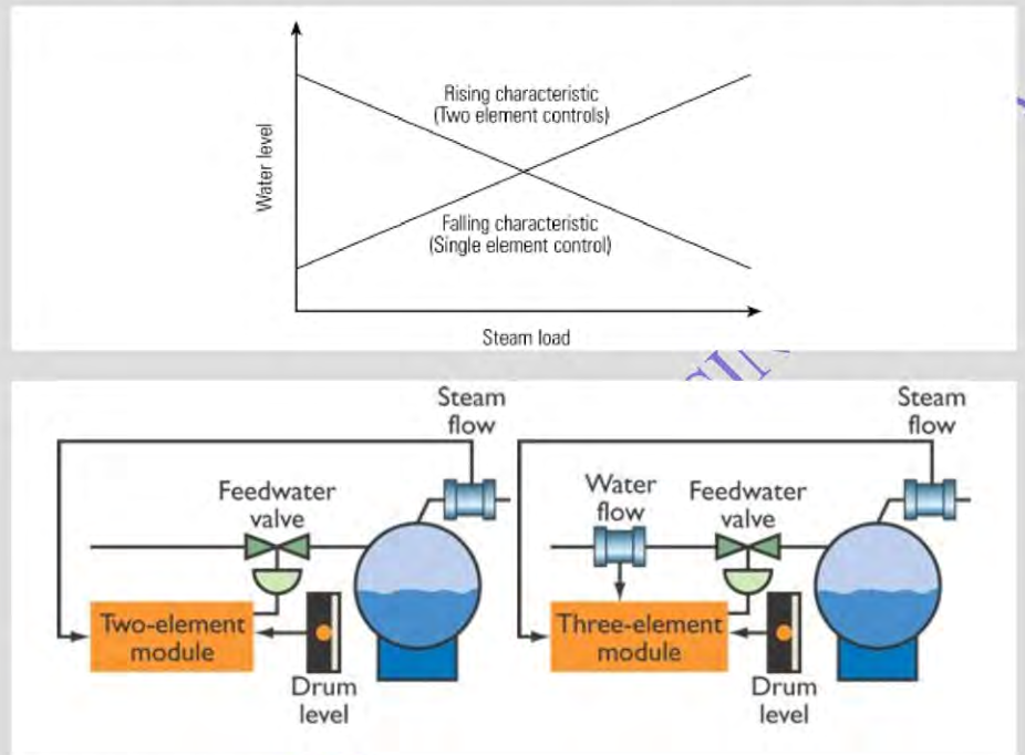
That figure shows the two control characteristics: the falling characteristic of single-element control, and the rising characteristic of two-element control, together with the inputs each loop uses. The rising characteristic is the one that avoids the collapse in level during a rapid load increase.
4.3 Three element — level plus steam flow plus feedwater flow
Adds feedwater flow as a third input. The level and steam elements correct for unmeasured disturbances, including:
- Blowdown variations due to changes in dissolved solids.
- Leaks in the boiler and superheater tubes.
- Variations in feedwater supply pressure.
- Steam leaks in the steam circuit.
The feedwater flow element responds rapidly to variations in feedwater demand arising from the steam flow feed-forward signal. For optimum control, both steam flow and feedwater flow are corrected for density.
Where it is used: where the system suffers from fluctuating feedwater pressure or flow, or where tighter drum level control is required. The three-element mode acts during high steam demand and can drop back to two-element mode at low demand, which stabilises control across a wide range of demand.
4.4 What good level control looks like
- Level steady at set point at constant load.
- Level responds smoothly to load changes without overshoot.
- Feedwater valve moves proportionally, not in jumps.
- Steam flow and feedwater flow track each other closely.
4.5 What poor level control looks like, and what it means
| Symptom | Likely causes |
|---|---|
| Continuous hunting at steady load | Wrong tuning; oversized or sticking valve; blocked impulse line; transmitter noise |
| Level falls when steam demand rises | Single-element control, or two/three-element feed-forward not working |
| Feed valve fully open with level still low | Undersized valve; low feedwater pressure; actual leak or gross blowdown; wrong control mode |
| Level rises when load falls, then alarms | Shrink not compensated; controller reacting to volumetric change |
| Frequent low-level trips at load change | Control mode wrong; feed-forward signal failed; transmitter lag |
| Both indicators disagree | Impulse line blockages on one; transmitter calibration; gauge glass fault |
5. Combustion control
5.1 What has to be balanced
Complete combustion requires:
- Correct fuel quantity.
- Correct air quantity, above the stoichiometric minimum.
- Correct atomisation.
- Correct mixing.
- Sufficient temperature in the ignition zone.
- Sufficient residence time for the largest droplet to burn.
The control system manages fuel and air quantity. The other four are hardware conditions that the operator maintains and the overhaul restores.
5.2 Reading combustion quality
| Indication | Good combustion | Poor combustion |
|---|---|---|
| Funnel smoke | Clean, or only a faint heat shimmer | Visible black, grey, or dense white smoke |
| Flame | Stable, bright, correct shape | Long, smoky, lifting, pulsating, or impinging |
| Furnace pressure | At set point, stable | Drifting, fluctuating |
| Flue-gas oxygen | At the correct excess-air value for the load | Too low → incomplete combustion; too high → excess losses |
| Uptake temperature | Design value for the load | High → fouling or excess air; low → underfiring |
| CO or smoke indication, where fitted | Low | Rising → incomplete combustion |
5.3 Too little air
- Incomplete combustion: carbon monoxide, unburnt hydrocarbons, soot.
- Visible black smoke — a MARPOL Annex VI problem, and evidence of poor maintenance.
- Carbon and soot deposits on the burner, in the furnace, and on the gas-side surfaces.
- Higher uptake temperature, because soot insulates.
- Increased risk of an uptake fire, because soot deposits are combustible.
5.4 Too much air
- Higher stack loss, because every kilogram of excess air is heated and thrown away.
- Reduced boiler efficiency.
- Flame destabilised — too much air velocity can lift a flame off the burner.
- Increased oxygen available for corrosion in the gas path, particularly at cold end surfaces where acid condensation can occur.
- Higher NOx formation.
5.5 The trap of correcting combustion with air alone
When combustion looks poor, the instinct is to open the air. That may reduce visible smoke while leaving the actual fault untouched: a worn burner tip still atomising poorly, or a fuel heater still not delivering the right viscosity.
The fuel will be burning badly with more air instead of less, and the deposits and consumption problems will continue. Correct the atomisation first, then set the air-fuel ratio.
6. Soot blowing
6.1 Why it is done
Combustion deposits soft soot on the gas-side surfaces. Soot is an insulator. As the layer builds:
- Heat transfer falls, so exit gas temperature rises and efficiency drops.
- The gas path resistance rises, so draught losses increase.
- The deposit is combustible, so it is a fire risk.
Soot blowing removes the soft deposit before it hardens and before it becomes a fire hazard.
6.2 Before blowing
- Confirm the boiler is on steady load, not manoeuvring.
- Confirm steam quality and pressure are adequate — the blower needs dry steam to work and to avoid adding moisture.
- Drain the soot-blower steam line. The line should be self-draining, and its drain valve should be open while the master valve is shut, so any leakage past the master valve escapes instead of wetting the line.
- Confirm uptake temperatures are normal. A high uptake temperature may mean a fire is already developing, and blowing could make it worse.
- Confirm no one is in the vicinity of the blowing arc or the furnace.
6.3 During blowing
- Follow the sequence and pattern required by the maker. The pattern is designed so that each blower covers its own gas path section.
- Watch furnace pressure, flame stability, and flue-gas temperature.
- Watch for any unexpected rise in temperature, which can indicate that a deposit has ignited.
- Stop immediately if anything abnormal occurs.
6.4 After blowing
- Confirm all blowers are returned to their parked position, clear of the gas path.
- Drain the steam line again.
- Note the reduction in exit gas temperature — that is the measurable proof the blowing worked. If the temperature does not come down, the deposit is not soft soot, and the surface needs mechanical or water washing at the next opportunity.
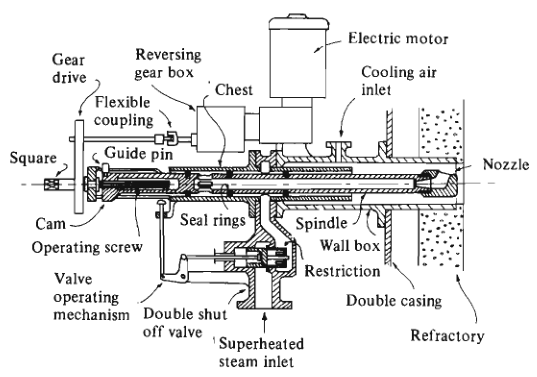
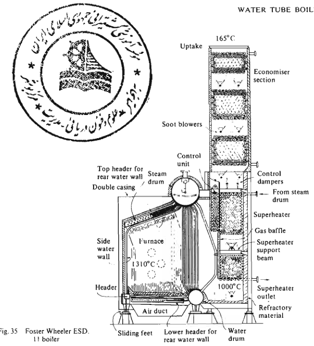

The two arrangements above show what the blower has to cover: each blower serves its own gas-path section over the generating tubes, superheater and economiser, with control dampers directing gas over the surfaces. That is why the maker specifies a sequence and pattern — missing a section leaves an insulating deposit that raises exit temperature and becomes a fire risk.
6.5 Hazards
- Blowing into a fire. If a deposit has already ignited, injecting steam may spread it or, depending on the circumstances, feed the reaction. Do not blow if a fire is suspected.
- Water in the blower line. Wet or cold steam wets the deposit and can cause corrosion and thermal shock on hot tubes, and can extinguish or destabilise the flame if it reaches the furnace.
- Blower stuck in the gas path. A blower that fails to retract becomes a hot, eroded obstruction and can fail.
- Steam line leakage into the gas path when the blower is parked — a continuous waste of steam and a corrosion source.
7. Logging and trending
7.1 Why trend beats snapshot
A single reading tells you the current state. A trend tells you the direction of travel, and it is the trend that predicts a failure.
A steam pressure of 7 bar against a set point of 7 bar is fine. The same pressure after three hours of steadily increasing firing rate for the same steam output is a warning that something is deteriorating.
7.2 What to record
- Steam pressure and temperature.
- Drum water level.
- Feedwater flow and temperature.
- Feedwater pump suction and discharge pressures.
- Fuel pressure, temperature, and viscosity.
- Burner firing rate or index.
- Furnace pressure.
- Flue-gas temperature at each available measurement point.
- Forced-draught fan current and damper position.
- Oxygen or excess-air reading.
- Boiler water test results.
- Blowdown carried out.
- Soot blowing carried out.
- Standby plant status.
- Defects and unusual observations.
Record at the frequency required for the plant, and always record the same items at the same time of day so comparisons are valid.
7.3 Reading the trends
| Trend | What it means | Action |
|---|---|---|
| Uptake temperature rising at constant load | Gas-side fouling, baffle damage, or increased excess air | Check air-fuel ratio; soot blow; plan inspection |
| Uptake temperature rising despite soot blowing | Hard deposit, internal blockage, or damaged surface | Reduce load if necessary; plan water wash or internal cleaning |
| Firing rate rising for the same steam output | Poor combustion, fouling, or heat transfer loss | Check burner, air-fuel ratio, gas-side cleanliness |
| Feedwater flow rising at steady steam flow | Tube leak, passing blowdown, or a level control problem | Check blowdown valves; compare feed flow with steam flow; look for leak signs |
| Level drifting with steady load | Control fault, or a slow leak | Check controller, transmitter, and valve; look for leaks |
| Furnace pressure drifting positive | Gas path resistance rising | Check uptake, dampers, blowers, and baffles |
| Stack temperature rising after soot blowing | Deposit is not soft soot | Plan mechanical cleaning at the next opportunity |
| Fan current rising at constant damper position | Increased system resistance | Check for blockage or deposit build-up in the air path |
| Chloride rising in boiler water | Seawater ingress | Find the source; follow the contamination procedure |
| Blowdown frequency increasing to hold solids | More contamination entering, or blowdown passing internally | Check the contamination source; check the blowdown valve |
7.4 The handover
A clean handover tells the next engineer:
- What the plant is doing and what it should be doing.
- What has changed during the watch.
- What is not working, and what has been done about it.
- What is likely to happen next, and what to watch.
A handover that says "all normal" when the uptake temperature has risen 40 °C over the watch is a failure of the watchkeeping duty.
8. Operating discipline
These are the habits that prevent accidents:
Never defeat a trip outside a formal, approved test.
Never run with an inoperable gauge glass, safety valve, or alarm. If it fails, the boiler comes off load until it is fixed or the Chief Engineer authorises operation with a documented alternative.
Report every abnormality, even if the boiler still runs. Most serious faults are visible in the log long before they become a failure.
Correct the cause. Adding air to cover smoke, or adding chemical to cover a rising chloride, hides the fault while it continues to develop.
Keep the plant clean. A leaking flange stains, corrodes, and hides the next leak next to it.
Follow the maker's limits for loading rate, warm-up, cool-down, and firing range. Those limits exist because of the thermal stress and circulation behaviour of that specific design.
Trust the direct indication when instruments disagree, then find out which one is wrong.
Do not chase the gauges. Steering the boiler by continuous small adjustments makes the plant unstable and hides the real control fault.