
Oil Content Monitoring and the 15 ppm Trip — Optics, Fluorescence and Testing
How the ship knows whether the water it is putting overboard is legal.
Key Principles at a Glance 8 points
- The old inspection glass failed in service on poor light and oily deposit building up on the inside of the glasses; the modern answer is a sampling pump with rapid flow through the chamber to keep the glasses clean.
- Direct light measures the light reaching a photo-cell as oil content rises; scattered light registers the light deflected sideways, which rises to a maximum and then falls as the sample turns opaque.
- Neither optical method can distinguish oil from rust, sand, sludge or biological growth — which is why the monitor is trusted as a trip device, not as a measuring instrument.
- Fluorescence discriminates in favour of oil: the sample passes through a UV-lit vertical cylinder and the photo-cell signal drives the diverting valve, though the instrument needs calibration for the fuel carried.
- Below 15 p.p.m. the overboard valves open; above it the three-way solenoid valve activates, an alarm sounds in the engine room, the bilge tank valve opens and the overboard valve closes.
- On hearing the alarm: open the oil drain cocks and check the oil control level, then stop the pump — nothing else.
- On a tanker, fibre optics keep the light source and photo-cell in the cargo control room while the sampling pump stays in the pump room, its shaft passing through a gas-tight bulkhead seal.
- Test the monitor by injecting oil into the sample line to prove the alarm circuit, then zero it on fresh water and span it on a liquid of known oil content.
1. Why the old method failed
The monitor's alarm and the automatic stopping device are legal fittings, not conveniences. They are not to be bypassed, isolated or defeated. If the monitor is faulty the discharge stops until it is repaired.
The original method of checking the discharge was entirely manual. Inspection glasses were fitted in the overboard discharge pipe, so that the flow could be sighted, illuminated by a lightbulb mounted opposite the viewer. The separator was shut down if there was any evidence of oil.
It failed in service for two reasons: poor light, and oily deposit building up on the inside of the glasses. A window that is both dimly lit and dirty on the inside is not a reliable instrument.
Why a photo-cell is not simply a better eye
Modern monitors work on the same optical principle, but there is a fundamental difference. The eye can register anything from a general emulsion to distinct globules of oil. A photo-cell cannot — it responds to the total light reaching it, and cannot tell one kind of obstruction from another.
Makers work round this with a sampling and mixing pump that draws a representative sample and presents it as a general opaqueness, with rapid flow through the sampling chamber to keep the glasses clean. The rapid flow is not incidental; it is the fix for the old fouling problem.
2. The two optical methods
Direct light
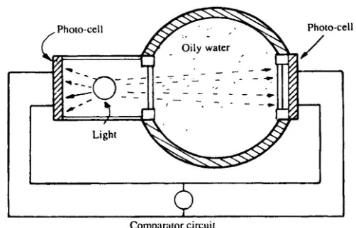
Water passes through a sample chamber and a strong light shines through it onto a photo-cell. The amount of light reaching the cell decreases as the oil content increases. The reading is compared against a reference cell, and the difference is registered on a meter calibrated to read directly in oil content.
Scattered light
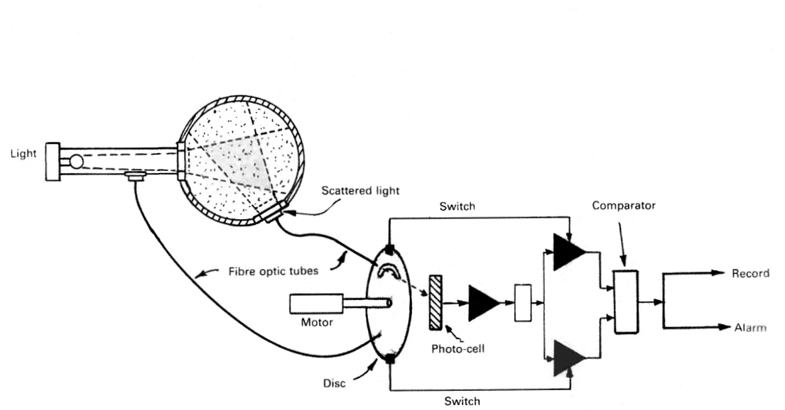
Scattered light monitoring registers the light scattered sideways by the oil particles rather than the light passing straight through. The behaviour is different and, at first sight, counter-intuitive: compared with the source light, the scattered light increases to a maximum and then decreases as oil content rises.
The reason is that at low oil content there are few particles to scatter light, and at very high oil content the sample becomes so opaque that light cannot reach the scattering particles at all. The useful measuring range is therefore the rising part of the curve.
The construction uses fibre optic tubes to carry light from the source, and from the scattered light window, to the photo-cell. A rotating slotted disc lets each shine alternately on the cell, and the two signals pass independently to a comparator. Taking the ratio rather than a single reading compensates for lamp ageing and window fouling.
The weakness common to both
Neither method can distinguish oil from any other particle in the water. Rust, sand, sludge and biological growth all register as oil. Chemical tests would be truer, but they are far too slow — the whole point of the monitor is to shut the discharge down within seconds, and no chemical test can do that.
This is why the monitor is a trip device rather than a measuring instrument. It is trusted to say "too much of something opaque", not to say "this much oil".
3. Fluorescence — the oil discharge monitoring principle
The most important modern principle is fluorescence, because it can discriminate in favour of oil.
When an atom receives radiated energy from a high-frequency source, electrons move to a higher energy level for a predictable period, then return and emit energy at a lower frequency. The emitted light is at a longer wavelength than the light that excited it — that is fluorescence.
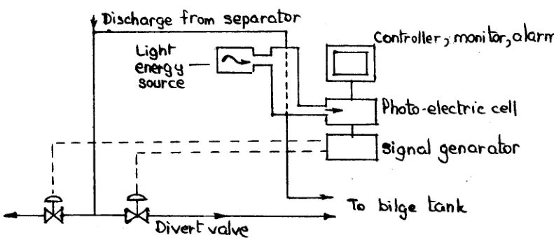
Oil fluoresces more easily than water, and this is the basis of oil-in-water detection. In practice, the sample passes through a vertical cylinder lit by an ultra-violet lamp at the top. The fluorescence is monitored by a photoelectric cell, which produces a signal dependent on the amount of oil present. Excess oil operates the diverting valve, and the discharge is diverted to the slop tank instead of going overboard.
The advantage over direct and scattered light is selectivity. The disadvantage is that not all oils fluoresce equally, so the instrument needs calibration for the fuel actually carried.
4. The 15 p.p.m. trip — what actually happens
The trip is the single most important automatic action on the plant, and it is worth being able to describe the exact sequence.
- Below 15 p.p.m. — the overboard valves open and the water is discharged.
- Above 15 p.p.m. — the three-way solenoid valve activates, an alarm sounds in the engine room, the bilge tank valve opens and the overboard valve closes.
The effect is that the discharge is diverted back into the bilge tank rather than going to sea, and the engineer is told about it. The alarm is both audible and visual.
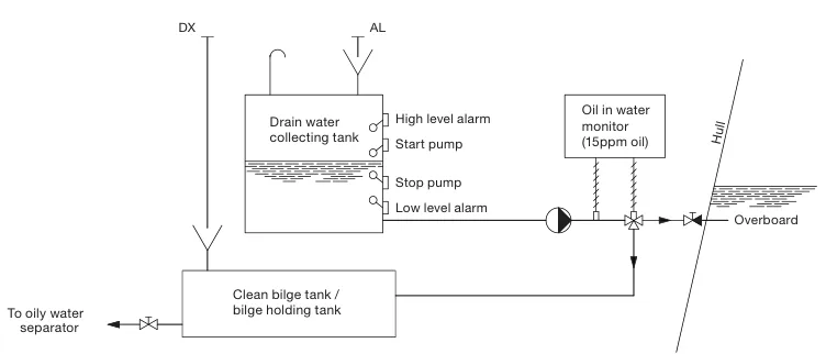
The action on hearing the alarm is not to defeat it. It is: open the oil drain cocks and check the oil control level, then stop the pump.
5. The tanker ballast arrangement
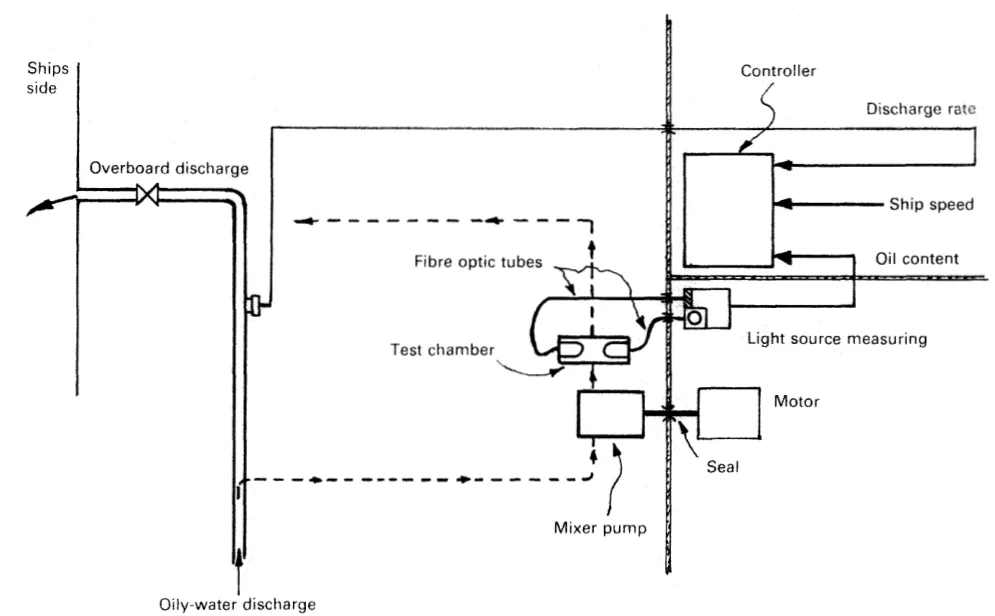
Tanker ballast monitoring has an extra problem to solve: the sampling equipment must sit in the pump room, which is a hazardous area, while the light source and the electronics must not.
The solution is fibre optics. Light is carried to and from the sampling chamber by fibre optic tubes, so that the light source and the photo-cell sit safely in the cargo control room alongside the control, recording and alarm console.
The sampling pump is in the pump room, to keep the sampling pipe short and the lag small, with its drive motor in the machinery space and the shaft passing through a gas-tight bulkhead seal. Oil content, discharge rate and ship's speed all go to the control computer for a permanent record, and alarms, automatic shutdown, back-flushing and recalibration are incorporated.
6. Testing and calibrating
A monitor that is never tested is not evidence of anything.
To test the oil discharge monitor: disconnect the sample pipe, switch on the monitor, inject oil into the sample line by opening the sample line valve, and the alarm will operate. This proves the alarm circuit and the trip.
Zero and span setting:
- Zero setting — pass fresh water through the cell. It should read 0 p.p.m.
- Span setting — pass a liquid of known oil content through the cell, and set the reading to match.
The purpose of both is to check the working condition of the sensor — that it responds, and that it responds in the right proportion. A monitor that passes the alarm test but has drifted on span will still trip, but at the wrong oil content.