
Brushless Alternator Working, Paralleling & AVR Explained
How excitation without brushes works, the ritual that parallels two live machines, and the loop that holds voltage.
Key Principles at a Glance 6 points
- Brushless means two machines on one shaft: stationary-field exciter feeding rotating-field main through a shaft-mounted rectifier — no brushes, no rings.
- Nothing starts without residual magnetism — the leftover field bootstraps excitation up to saturation-limited equilibrium; too much field resistance kills the buildup.
- Paralleling matches voltage, frequency, phase and phase sequence: synchroscope slow clockwise, breaker just before 12 — lamps read top-dark with two equally bright when correct.
- The incoming set runs slightly fast so it takes load on closing; a slow incoming set would motorise and drag the bus down with it.
- AVR closes the loop: sensed output vs zener reference drives exciter field through thyristors, with droop CT sharing, V/Hz guarding and soft-start manners.
- Three protections stand watch (overcurrent at ~150% with delay, reverse power, undervoltage) — reverse power is proved by load-shifting one set into motoring.
1. Excitation Without Touching Parts
Idea in one line: a small stationary current steers a spinning rectifier that feeds the big rotating field, so nothing ever needs to touch the shaft.
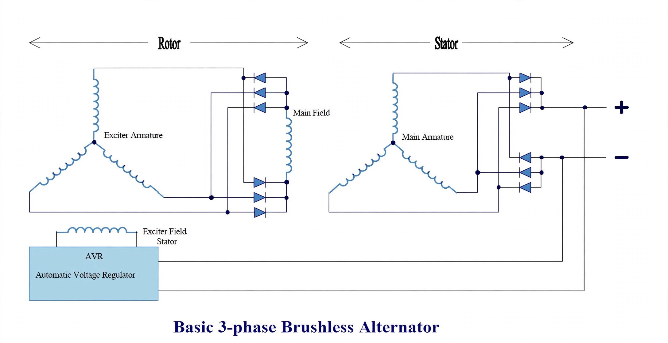
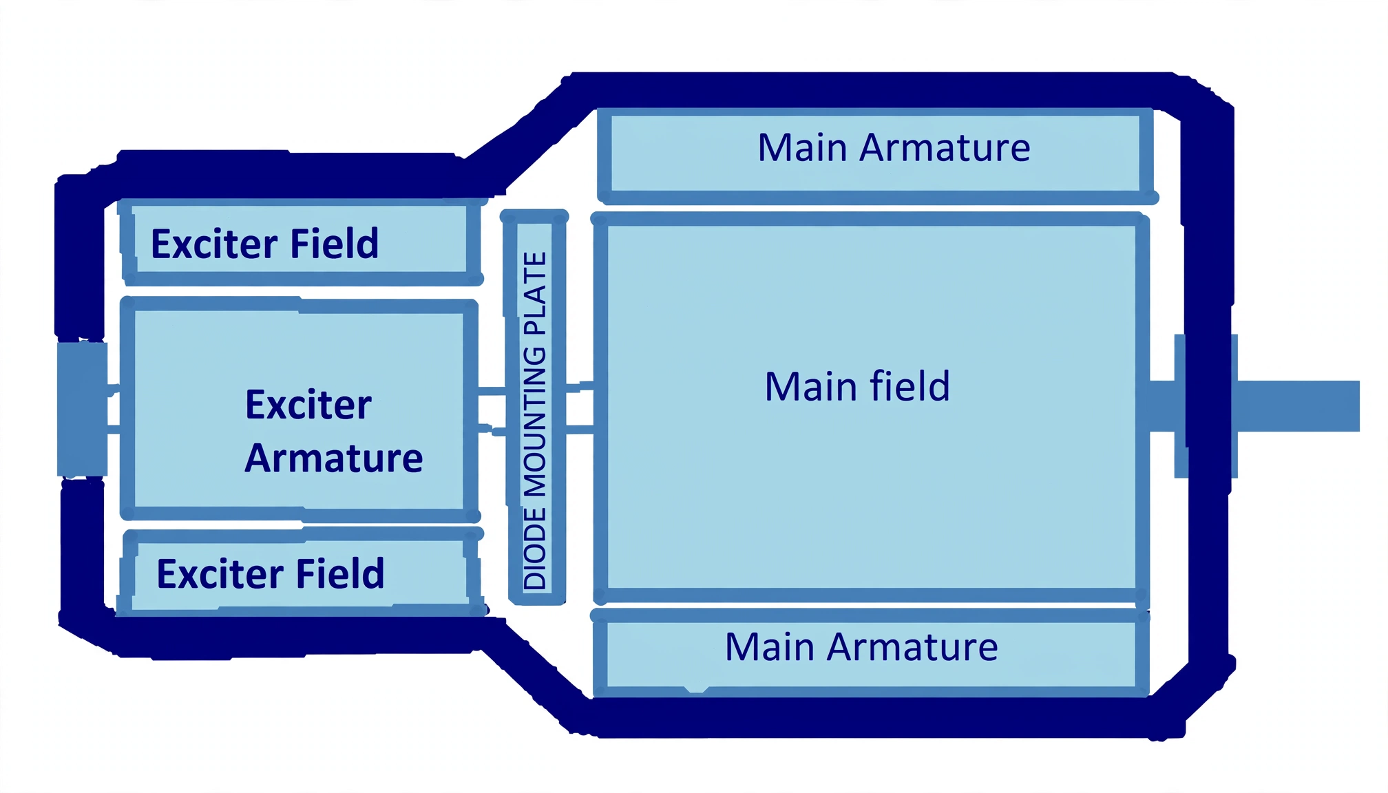
A brushless alternator is two alternators built end-to-end on one shaft. The smaller one is the exciter; the larger one is the main machine — and they are wired back-to-front on purpose.
Exciter stage
Stationary exciter field feeds a rotating exciter armature (power coils).
Shaft rectifier
Three-phase exciter output rectifies on the rotor (rotating rectifier assembly) straight into the main rotating field.
Main armature
The stationary main armature delivers load power. Varying the small exciter current steers the entire output.
Bootstrapping: residual magnetism seeds the whole loop — leftover field makes a little EMF, which feeds field current, which grows flux, until saturation caps it at equilibrium. If field resistance exceeds the critical value, the loop never builds and the set stays dead.
Maintenance is sea-duty realism: isolate, lock out and post notices before touching anything. Clean ventilation passages and filters, prove stator and rotor insulation, hold the air gap at 1.5–2 mm, check terminal-box tightness and cable glands, keep forced ventilation and heaters working — then run a no-load test and log noise, temperature and volts against PMS.
2. Paralleling Ritual — Synchroscope and Lamps
Idea in one line: two live sources may share one bus only at the instant their voltages agree in size, speed and angle — every instrument here hunts that instant.
Four conditions, no exceptions: same voltage, same frequency, same phase, same phase sequence. Miss any one and closing the breaker parallels two disagreeing sources through the bus.
Meters proven, set started correctly, pressures, temperatures and alarms sane, prime mover stable for a full minute.
Match voltages bus-to-incoming, selector to the incoming set, and read the synchroscope: clockwise means fast, counter-clockwise slow.
Trim the governor to a slow clockwise drift (~4 s/rev) — incoming slightly fast so it takes load on closing instead of motorising and dragging the bus.
Close the breaker just before 12 (mechanism delay lands the contacts on phase), selector off, share load across governors.
When the scope dies, lamps take over. Three bulbs wire bus-to-incoming: as speeds differ they breathe bright and dark at the slip rate. Dark-lamp wiring goes dark at matched phase; bright-lamp wiring goes bright. The sequence method is preferred — lamp brightness appears to rotate, clockwise for fast, anti-clockwise for slow, and correct sync reads the top (key) lamp dark with the two bottom lamps equally bright.
Oral closer: name the four conditions, the slow-clockwise drift, close-just-before-12 for mechanism delay, and 2-bright-1-dark as the lamp backup.
3. AVR Loop & the Three Protections
Idea in one line: the AVR watches the terminals and trims the tiny exciter current so the big output never notices load, heat or speed changes.
The sensing unit steps output down, rectifies and smooths it to a DC signal, compares it against a zener-diode reference, and amplifies the error into the field-circuit thyristors — voltage restored against load, speed, temperature and power-factor drift.
Droop CTs
Let paralleled sets share reactive load instead of fighting over it.
V/Hz slope
Sheds excitation under speed so turbocharged recovery is not strangled.
Soft-start + latch
Ramps volts up sanely; latched shutdown cages runaway excitation until standstill.
Three protections stand watch: overcurrent (~150% with ~20 s delay — rides brief overloads, still catches short circuits), reverse power (a motoring set draws from the bus and tortures its prime mover), undervoltage (collapsed field or bus). Reverse current cannot be sensed on AC, so the relay watches reverse power direction instead.
Proving reverse power: carry the ship on one set while governor-shifting the other into a whisper of load — its breaker must trip as motoring begins. Preferential trips get the same honesty: dial the overload setting down, run, and watch non-essentials shed in their 5/10/15 s stages.