
Tiller and Rapson Slide — Mechanical Advantage, Clearances and Fastenings
The mechanism that turns the straight-line push of the rams into the rotation of the rudder stock.
Key Principles at a Glance 6 points
- Three things are worth watching on this mechanism: the sliding surfaces, the clearances, and the security of the fastenings.
- The tiller arm slides in the swivel block, the codpiece slides in the jaws and the crosshead slippers slide on the guide beam — all three are lubricated, and all three wear.
- A dry sliding surface in the steering gear is a finding, and the routine check list calls for the sliding surfaces to be verified as lubricated and the grease nipples checked.
- Excessive clearance in the slide, the crosshead or the swivel block shows up as a rudder that does not hold its angle, and it is measured and recorded at survey.
- The two rams of a pair are bolted together, the slippers are bolted to the ram, the thrust ring is dowelled and the tiller is keyed — every one of those is a fastening carrying a cyclic load, and a loose one turns a designed load path into an impact.
- The mechanical advantage of the Rapson slide is what fixes the whole design, because it sets how much ram force is needed for the rudder torque required.
1. The tiller
The tiller and the slide are set up to the maker's dimensions and the wear is measured at survey. The clearances in this mechanism are what let it work, and what eventually stop it working.
The tiller is keyed to the rudder stock. It is the arm that the rams push on, and it is the last mechanical link between the steering gear and the rudder.
It is of forged or cast steel, with one arm — or two, for a four-ram gear. The single-arm tiller is pushed one way by a ram on one side and the other way by a ram on the opposite side. The double-arm tiller has two arms working on the same principle, with a pair of rams on each.
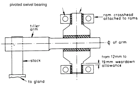
The tiller is machined smooth to slide in a swivel block arrangement designed to convert the linear movement of the rams into the rotary movement of the tiller arms and rudder stock. That is the whole function of the tiller in a ram type gear: not merely to be pushed, but to be pushed in a way that produces rotation. The machined smooth face is what allows the swivel block to slide along the tiller as it turns, which is the heart of the Rapson slide.
The key is what transmits the torque from the tiller to the stock. The tiller is not merely clamped to the stock; it is keyed, so that the torque goes through a positive drive rather than through friction. The key is a highly stressed component and is one of the items inspected when the gear is opened up.
2. The Rapson slide
This device, known as a Rapson slide, is used for many, but not all, ram type gears.
The Rapson slide is the mechanism that converts the straight-line motion of the rams into the rotation of the tiller. The essential idea is that the ram crosshead slides along the tiller arm as the tiller turns. The point at which the ram's force is applied therefore moves along the arm, and that is what produces the varying mechanical advantage described in section 5.
The name is worth knowing because the mechanism appears in three different forms in this volume — as the crosshead and swivel block of a two-ram gear, as the fork type tiller, and as the arrangement of a four-ram gear — and they are all the same principle applied differently.
3. The ram crosshead and the swivel block
The Rapson slide is built out of four parts, and it is worth following them in order.
The rams are one-piece steel forgings, with the working surface ground to a high finish. The finish matters because the ram surface is a sliding seal surface — it runs through the cylinder's neck bush and seal, and any roughness there tears the seal.
Each pair of Rapson slide rams is bolted together, the joined ends being bored vertically and bushed to form top and bottom bearings for the projecting spigots on the swivel block. The two rams of a pair are bolted end to end, and the joint between them is bored out to form a vertical bearing housing. The swivel block's spigots — its top and bottom projections — sit in those bearings, so the swivel block can rotate between the two rams.
Crosshead slippers, bolted to the face of the central section of the rams, slide on the machined surfaces of the guide beam. The slippers take the side thrust of the ram and keep it running straight; the guide beam is the surface they run on. The slipper is a replaceable wearing part bolted to the ram, which is the right way round: the cheap part wears, not the expensive one.
The tiller arm itself slides through the swivel block. The swivel block is mounted on the tiller arm, and as the rams move the block travels along the arm while the arm rotates. The arm's machined smooth faces are what make that sliding possible.
So the chain is: ram → slipper → guide beam for straight-line guidance, and ram → bolted joint → swivel block bearings → swivel block → tiller arm for the transmission of force and the conversion into rotation.
4. The guide beams and the cylinder feet
Two structural details make the arrangement work.
Guide beams also serve to brace each pair of cylinders against the tendency for them to be pushed apart by the hydraulic pressure. A pair of opposed rams pushing towards each other is a pair of forces trying to separate the two cylinders they are mounted in. The guide beam ties the two cylinders together and takes that load, so the pressure in the cylinders does not have to be carried by the foundations alone.
The cylinders have substantial feet bolted to the stools on which the gear is mounted. The cylinder feet carry the reaction of the ram force into the ship's structure — the stools are the foundations, and they are substantial because the loads are large and cyclic.
The guide beam and the cylinder feet together are why a ram type gear looks the way it does: a heavy frame of cylinders, guide beams and stools, with the tiller working in the middle of it.
5. The fork type tiller
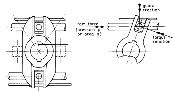
This is a more recent design, in which the rams as a single forging act upon a codpiece which slides in slots which are machined into upper and lower jaw pieces of the tiller.
The difference from the Rapson slide is in how the ram meets the tiller. Instead of the ram being bolted to a crosshead that carries a swivel block, the ram is a single forging with a codpiece — a block formed on the end of the ram — and the codpiece slides in slots machined into upper and lower jaws of the tiller.
The jaws straddle the codpiece. As the ram moves, the codpiece slides along the slots, and the tiller turns. The arrangement is stronger and simpler than a separate crosshead and swivel block, because there are fewer parts and the load path is more direct.
The fork type tiller is also the answer to the rule in Chapter 1 that requires two tillers, or their equivalent, unless the working tiller is of special design and strength. The fork type tiller is exactly such a special design: a heavy forging whose failure is not credible.
6. Mechanical advantage
This is the part of the tiller's behaviour that is worth understanding properly, because it explains the relief valve settings and the size of the rudder stock.
The mechanical advantage of the Rapson slide, neglecting friction, increases with angle, and it is 1.53 at 36°. At mid position the advantage is lower; as the tiller turns and the rudder goes over, the point at which the ram pushes moves along the arm and the advantage rises.
For the rotary vane type, the mechanical advantage is unity for all angles. The vane gear turns the stock directly, with no linkage, so there is no geometry to vary the advantage. One unit of force at the vane gives one unit of torque-producing effort, whatever the rudder angle.
The difference matters. A ram gear at a large rudder angle produces more torque for the same ram force than it does at midships, whereas a vane gear produces the same torque at every angle. That is one of the reasons a ram gear can be built to a higher torque capacity than a vane gear of similar size.
Why the mechanical advantage fixes the whole design
The chain of reasoning runs like this, and it is worth following because it connects three things that otherwise look unrelated.
- The relief valve lifting pressure is set — at a figure between 80 and 190 bar, depending on the design (see Chapter 11).
- That setting fixes the maximum ram load, because the ram force is the hydraulic pressure multiplied by the ram area, and the pressure can never exceed the relief valve setting.
- Applying the leverage of the tiller to the maximum ram load gives the maximum torque that can be exerted on the rudder stock.
- The maximum torque fixes the maximum torsional stress in the stock, which is limited to about 34.5 MN/m².
- That stress allows the stock diameter to be calculated — and the same torque allows the power and the size of the motor and pump to be calculated.
So the relief valve setting is not merely a protection device. It is the number from which the strength of the rudder stock and the size of the power unit are derived. A gear whose relief valves have been set higher than the design figure has been re-designed, by whoever adjusted them, to a stock that does not exist.
7. The tiller bearing and the carrier
The tiller sits on top of the rudder stock, and the bearing that carries the rudder's weight is built around the top of the stock at the same place. The two are described together in the older accounts, and it is worth knowing how they fit, even though the carrier bearing itself is dealt with in Chapter 2.
The tiller-rudderhead bearing and carrier usually have the main casting of cast steel, with a large machined base for fitting to the deck. The casting is the body of the whole assembly: it carries the bearing surfaces, it locates the stock, and it is bolted down to the deck.
A bronze thrust ring is on top of this casting, and the tiller boss has a machined ring face to go against this thrust face. The thrust ring is the bearing surface; the tiller boss — the thickened hub of the tiller where it sits on the stock — has a machined face that bears on it. The rudder's weight goes down through the tiller boss into the thrust ring.
The thrust ring is in halves and is dowelled against rotation, and lubrication is provided. The ring is split so it can be fitted around the stock, and dowelled so that it cannot turn with the stock — a thrust ring that rotated would not be a bearing, it would be a wearing surface turning against its own housing.
The main gland bush, in halves, is usually of gunmetal and is grease lubricated. The gland bush is the lower bearing that keeps the stock centred, and it is the journal half of the arrangement.
Fabricated assemblies are common in modern practice, which means the casting is replaced by a welded fabrication — lighter for the same strength, and easier to make in the sizes modern rudders need.
Rudder, stock and other parts have weight transmission to the tiller by means of a steel support plate and eyebolt on top of the rudder stock. This is the arrangement that carries the rudder's weight from the stock into the tiller and hence into the thrust ring. The eyebolt is also what the rudder is lifted by when the stock has to be raised — the lifting operation is described in Chapter 10.
8. What the tiller and the slide tell you
Three things are worth watching on this mechanism.
The sliding surfaces. The tiller arm slides in the swivel block, the codpiece slides in the jaws, and the crosshead slippers slide on the guide beam. All three are lubricated, and all three wear. A dry sliding surface in the steering gear is a finding, and the routine check list in Chapter 9 calls for the sliding surfaces to be verified as lubricated and the grease nipples checked.
The clearances. The clearances in the slide, the crosshead and the swivel block are what allow the mechanism to move; when they grow, the gear becomes loose and the rudder begins to wander about the angle ordered. Excessive clearance in this mechanism shows up as a rudder that does not hold its angle, and it is measured and recorded at survey.
The security of the fastenings. The two rams of a pair are bolted together; the slippers are bolted to the ram; the thrust ring is dowelled; the tiller is keyed. Every one of those is a fastening carrying a cyclic load, and a loose one of them turns a designed load path into an impact.