
Steering Gear Maintenance — Rudder Drop, Bearing Clearances and Overhaul
The work done on the steering gear itself — the measurements taken, the rudder lifted, the cones repaired, the system charged, the seals renewed.
Key Principles at a Glance 5 points
- Everything in this chapter is a measurement: rudder drop, jumping clearance, bearing clearances, blue marking contact and push-up force — none of the decisions made at a dry dock are made by looking, but by comparing one number with another.
- Everything is done to an approved procedure — the welding procedure, the charging sequence, the lifting sequence, the tightening torques — because a steering gear is a component with no spare.
- Everything is recorded: the survey report form, the log entries and the oil analysis results, because the record turns a measurement into a trend and the trend turns a repair into a planned job instead of an emergency.
- The rudder, the stock and the carrier bearing cannot be duplicated, so the maintenance of the rudder and its bearings is the maintenance that has no backup.
- The pumps can be duplicated, the rams can be duplicated and the control systems can be duplicated — the rudder cannot, and that is what decides where the measurements and the procedures go.
1. The pattern of maintenance
The maker's manual is read before any of this is started, and the measurements are recorded against the originals. Work on a rudder and its stock is work on a highly stressed component there is only one of, and it is done to an approved procedure or not at all.
Steering gear maintenance falls into four kinds of work, and it is worth separating them because they are triggered by different things.
Running maintenance — lubrication, leak correction, topping up, filter cleaning. Triggered by the daily and weekly checks in Chapter 9. Small, frequent and mostly done by the duty engineer.
Interval maintenance — the monthly, three-monthly and six-monthly items: filters, alarms, drills, oil samples. Triggered by the calendar.
Survey maintenance — the measurements and overhauls done at dry dock under the continuous survey of machinery: the ram seals, the bearing weardown, the rudder drop, the bearing clearances. Triggered by the survey cycle.
Repair maintenance — what is done when something has failed. Triggered by a fault, and described in Chapter 11.
The dry-dock work is the part that needs planning, because it is the part that needs the ship out of the water and the rudder off its bearings. Everything in sections 2 to 8 of this chapter is dry-dock work.
2. The rudder carrier bearing
The carrier bearing is where the wear concentrates, and the maintenance of it is a matter of measurement first. The wear itself — what causes it, the design allowance of about 19 to 20 mm, the 3 to 6 mm working limit and the trammel gauge measurement — belongs to Chapter 2. What follows here is the work done when the measurement says it is due.
Restoring the weardown allowance is the maintenance action, and it means bringing the stock back up to its correct height. The ways it is done depend on the design:
- The thrust ring is renewed, if it has worn to that point.
- The thrust ring is shimmed or machined, if a smaller correction is needed.
- The carrier is re-chocked, if the bearing has moved rather than worn.
The work requires the rudder's weight to be taken off the bearing, which is the lifting operation in section 4.
The grease is renewed. The bearing is grease lubricated with a water-resistant calcium soap base grease containing graphite (Chapter 2), and the old grease is displaced by new as the bearing is lubricated. On a screw-down lubricator this happens as a matter of course; on an automatic lubricator the reservoir is replenished and the feed checked.
3. Measuring the bearing clearances
The bearing clearances are the measurements that decide whether the rudder has to come off its bearings, and the method is straightforward.
Measurement of all the bearing clearances is to be carried out.
The outer diameter of the pintle can be measured with external callipers. The inner diameter of the bearing needs to be measured with internal callipers.
The diameter should be measured at three different locations — top, centre and bottom — and the average of these values is to be taken.
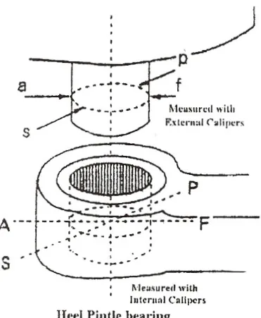
Three measurements and an average, because a worn bearing is not round and a worn pintle is not cylindrical. A single measurement would give a clearance figure that could be anything, depending on where it was taken. The average of three is a figure that can be compared with the original and with the previous survey.
The clearance is then the difference between the bearing's internal diameter and the pintle's external diameter, and it is the figure that is compared against the maker's limit.
The survey report
The measurements are recorded on a report form, and the form is worth knowing because it shows what is measured and what is compared.
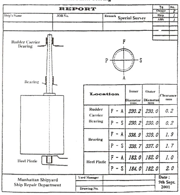
The report covers the rudder carrier bearing and the heel pintle bearing, and each is recorded in both the fore-and-aft (F–A) and port-and-starboard (P–S) directions, with an inner diameter, an outer diameter and a clearance for each.
The two directions matter because a rudder loads its bearings differently in each. The fore-and-aft load is from the water pressure on the rudder and from the propeller slipstream; the port-and-starboard load is from the rudder being put over. Measuring both is how a bearing that has worn unevenly is detected.
4. Lifting and removing the rudder
When the bearing clearances are outside limits, or when the bearing is found damaged, the rudder has to come off its bearings.
After the rudder bearing clearances have been checked, and the condition of the bearing is inspected, any abnormality found would necessitate the lifting or removal of the rudder, depending upon its construction.
In rudders with upper and lower pintle bearings, the rudder has to be lifted. For a "hanging" rudder, the rudder is lowered. For a Simplex type rudder, the rudder post has to be removed.
In any case, the tiller needs to be disconnected from the steering gear and removed, while the jumping stopper also needs to be removed.
So the first work is always the same whatever the rudder type: disconnect the steering gear from the rudder and remove the jumping stopper. The steering gear must be isolated and immobilised first, by the procedure in Chapter 9.
Jacking up the rudder
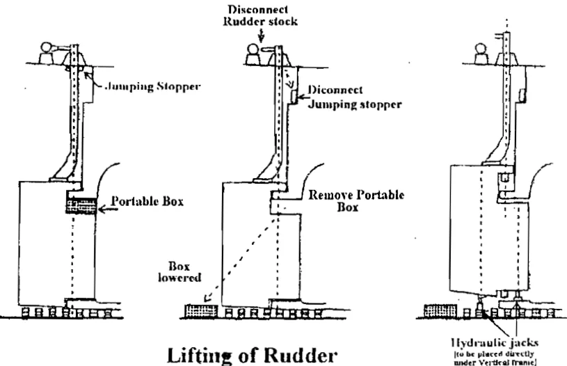
The sketch shows the steps to be taken for lifting a rudder having upper and lower pintle bearings.
The rudder needs to be jacked up, using hydraulic jacks, which must be positioned with care, under the vertical frame, otherwise the bottom of the rudder is likely to be damaged.
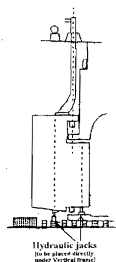
The instruction about jack position is the most important sentence in this chapter, and it is worth stating plainly. A rudder is a box structure with plating over an internal frame. The plating is thin and is not designed to carry a point load; the frame is. A jack placed under the plating will push the plating in and damage the rudder. A jack placed under the frame will lift the rudder.
If the sequence is not followed correctly, the rudder is likely to drop and break the "shoe piece", which means that adequate care should be taken.
A rudder weighs many tonnes, and once it is off its bearings it is held only by the jacks and the lifting arrangement. A rudder that drops will break the shoe piece — the bottom support — and will also be dangerous. This is why the operation is done to a written sequence with the makers' instructions to hand.
5. What is checked after the rudder is lifted
With the rudder off its bearings, the parts that cannot be seen at any other time become accessible, and there is a definite list of things to look at.
Check the carrier disc surface for damage.
Check the sleeve for thickness.
Check the hole for thickness.
Those three are the checks called out on the diagram, and each is a different failure mode:
- The carrier disc surface — the thrust face itself. It is checked for scoring, for uneven wear, and for the damage that a period of poor lubrication leaves behind.
- The sleeve — the wearing sleeve on the pintle or the stock. It is checked for thickness, because if it has worn thin it will fail rather than wear further.
- The hole — the bearing bore in the rudder or the stern frame. It is checked for thickness for the same reason.
The components seen when the rudder is lifted are the weight sleeve, the rudder stock, the retainer, the bearing disc, the bush, the gland, the gland packing, the jumping stopper, the rudder carrier bearing and the heel disc.
The bush and the bearing disc are the bearing surfaces; the retainer holds the assembly together; the gland and gland packing seal the rudder stock where it passes through the hull, and a leaking gland is a source of water in the steering gear compartment. The heel disc is the bearing at the very bottom.
6. Repairing the pintle cone
The pintle cone is the tapered joint between the pintle and the rudder, and it is a joint that must transmit the whole of the rudder's steering torque by friction. Repairing it is a controlled procedure.
The welding procedure, which is approved, is as below:
- Preheating.
- Repairs by automatic welding, and approved welding consumables.
- Stress relieving, done at 500 to 600 °C.
- Final machining.
- Straightness check, which must be carried out.
- Magnetic particle inspection, completed to satisfaction.
- During mounting, blue marking must show a minimum of 70 per cent contact area.
- The push-up force should be equal to the weight of the stock pintle. A surface pressure at 40 N/mm² is considered sufficient to absorb the total torque by friction.
- The nut must be secured. A welded flat bar is recommended.
- Sealing of the cone should be finally checked.
The list repays being read as three separate concerns.
Steps 1 to 6 are about making the metal sound. Preheating, automatic welding, stress relieving, machining, a straightness check and a magnetic particle inspection. The stress relief at 500 to 600 °C is what removes the residual stresses left by welding in a component that will carry cyclic load; the magnetic particle inspection is what proves the weld is sound before it is relied on.
Step 7 is about the fit. Blue marking must show a minimum of 70 per cent contact area. Blue marking is the method of checking how well two tapered surfaces mate: one is coated with marking compound, the two are brought together and separated, and the pattern of contact is read. Seventy per cent is a demanding figure, and it is demanding because the joint transmits torque by friction and friction needs contact.
Steps 8 and 9 are about holding it there. The push-up force equals the weight of the stock pintle, and the surface pressure of 40 N/mm² is the figure considered sufficient to absorb the total torque by friction. So the cone is not held by the nut against a shoulder; it is forced onto its taper hydraulically with a defined force, and the friction of the taper is what transmits the torque. The nut then only has to keep it there, which is why a welded flat bar is recommended as the securing method rather than a tab washer.
Step 10 is about water. The sealing of the cone is checked finally, because a cone that lets water in will corrode, and a corroded taper loses its fit and its friction.
Ribbing
Ribbing can be repaired by:
- Filing down.
- Smoothing away with emery cloth.
Ribbing is a pattern of fine ridges on a shaft or bearing surface, and it is a surface defect rather than a structural one. Filing and emery cloth are the right treatments because the object is to restore the surface, not to remove metal.
7. Charging and purging the gear
The steering gear itself — the cylinders, the pipes and the pump — must be full of oil and free of air, in the same way as the telemotor (Chapter 7). Filling it is a commissioning and maintenance operation.
The steering gear itself must be completely filled with oil and all air must be excluded.
Thus the air release valves are opened on the hydraulic cylinders and pumps, also the stop valves and by-pass valves in the system.
The variable delivery pump can be used to pump the oil around the system, while keeping the replenishing tank topped up. It can be put just on stroke by the handwheel and turned by a bar.
That last point is worth noting: the pump is used as the filling pump, and it is turned by hand. Putting the pump just on stroke and turning it with a bar means the filling is done slowly and under control, with somebody able to watch the air release valves rather than relying on the pump running at speed.
The rams may be filled through the filling holes until all air has been displaced, before starting to pump the system through.
When all air has been purged from the system, and the level in the replenishing tank ceases to fall, the air release valves are closed.
The test for completion is the level: when the level in the replenishing tank stops falling, the system is full. A system that is still taking oil is a system that still has air in it.
Finally the by-pass and stop valves are set for normal running, and the pump is started. Using the hand control, the gear is then run from hard over to hard over slowly, and the air release valves are again checked.
The final hard-over to hard-over run is what distributes the oil into the last pockets of the system — the ends of the cylinders, which the filling operation may not have reached. The air release valves are checked again afterwards because that is where the air ends up.
Charging methods for steering gears and telemotors vary from one type to another.
Filling by rotating the gear
There is a second method, used on the two-ram gears, and it is the one an engineer is more likely to meet.
The gear is filled by coupling up to the hand steering and rotating port and starboard with the motor running, having previously filled the suction sump or replenishing tank and the ram cylinders, with the replenishing valves and bypass valves open. The bypass valves are then shut and the gear fully rotated port and starboard, whilst the air is purged from the ram cylinders and so on at the air cocks.
So: fill the tank and the cylinders by hand, leave the bypasses open so the oil can move freely, rotate the gear with the motor to push the oil round, then shut the bypasses and rotate again to purge the air. The bypasses being open during the first rotation is what lets the oil reach both sides of the system; shutting them for the second rotation is what builds the pressure that drives the air out at the cocks.
Purging a four-ram system
The four-ram gear has its own purge procedure, and it is worth having as a worked example because it names the figures.
Purging air from a four-ram type steering gear system:
- Carry out system isolation.
- In the case of a hydraulic ram type steering gear, the casing and sump should be maintained with 75 per cent of its capacity.
- A turning bar is inserted inside the holes of the flexible coupling — that is, between the motors and the pump.
- Then the air release purge screws on the cylinders are opened partially.
The 75 per cent is the same figure used for the cold-weather tank level in Chapter 9, and for the same reason: the oil expands as it warms, and the system needs room for it. The turning bar in the coupling is the same technique as the bar on the pump — turning the pump by hand so that the filling is slow and controlled.
The purge screws being opened partially is deliberate. A purge screw opened fully lets oil out as fast as it lets air out, and the system is emptied while it is being purged. Partially open lets the air escape and keeps the oil.
8. The ram seals and the bushes
The ram seals are the main wearing items inside the gear, and they are renewed at the dry-dock overhaul.
The dry-dock overhaul of the steering gear system includes the replacement of ram seals, the measurement of bearing weardown, and so on.
The seal arrangement on a ram type gear is described in Chapter 4: the ram is machined and ground to slide in the gunmetal neck bushes and chevron type seals of the cylinders. Two separate components, doing two separate jobs:
- The gunmetal neck bush supports the ram and takes the side load. It is a bearing and it wears.
- The chevron type seal is the pressure seal. A chevron seal is a stack of V-section rings, and it seals more tightly as the pressure rises.
The ram surface itself is the sealing surface, which is why it is ground to a high finish and why it is lubricated with the system oil rather than grease (Chapter 9). A scored or corroded ram will destroy a new seal, so the ram is inspected at the same time as the seal is renewed.
On a four-ram gear the seals are renewed on all four cylinders at once, because a gear that has been taken apart to that extent is not put back together with three new seals and one old one.
9. The pumps
The pumps are maintained as assemblies, with the work limited to what can be done in the steering flat.
At the pump block are non-return valves and connections leading to the sump or replenishing tank, to act as suction and replenishing leads. The ram pipes to and from the pump to the rams are also led into the pump block.
The pump block is therefore where the pump connects to everything else, and it is where leaks are found and where the non-return valves that control the replenishing flow are examined.
The oil used in the system is well filtered pure lubricating oil.
Beyond that, the maintenance of a variable delivery pump is largely a matter of:
- The oil — kept clean, kept at the right level, analysed every six months.
- The filters — the 50 micron inlet filter and the return line silt filter, cleaned when the differential pressure says so (Chapter 9).
- The seals — the pump shaft seal and the casing joints, renewed when they leak.
- The pump casing cooling flow — the auxiliary pump's discharge through the casings (Chapter 4), which must not be blocked.
A complete armature and field coil would normally be carried as part of the spare gear on an all-electric installation. That is the same point made in Chapter 8: an emergency arrangement that cannot be repaired is not an emergency arrangement, and a spare armature is what makes a failed machine repairable.
The internal overhaul of a variable delivery pump — the pistons, the floating ring or swash plate, the valve plate and the servo mechanism — is a workshop job to the maker's instructions, not a job to be done in the steering flat.
10. The oil
The oil is the part of the steering gear that is easiest to neglect and cheapest to look after, and it decides the life of everything else.
The checks on the oil are:
- Level — daily, in the replenishing tank and the storage tank (Chapter 9).
- Temperature and pressure — daily, for any deviation from normal (Chapter 9).
- Appearance — daily, for water, dirt or discolouration.
- Filter condition — monthly, or when the differential pressure indicates (Chapter 9).
- Laboratory analysis — six-monthly (Chapter 9), for water content, viscosity, acidity and wear metals.
The oil level in the storage tank has a specific purpose: the rules require it to hold at least one complete system replenishment (Chapter 1), so that a system that has been drained can be refilled. A storage tank that has been raided for other uses is a storage tank that will not do its job.
The cleanliness requirement is a rule (Chapter 1), and it is met by the filters. Keeping the oil clean is what keeps the servo valves, the change-over valves and the pump's internal clearances working; a steering gear fails from dirt far more often than it fails from wear.
11. What maintenance is really for
The work in this chapter has a shape, and it is the same shape as the routine in Chapter 9.
Everything here is a measurement. The rudder drop, the jumping clearance, the bearing clearances, the blue marking contact, the push-up force. None of the decisions made at a dry dock are made by looking; they are made by comparing a number with another number.
Everything here is done to an approved procedure. The welding procedure, the charging sequence, the lifting sequence, the tightening torques. A steering gear is a component with no spare, and work on it is done the way the maker says or not at all.
Everything here is recorded. The survey report form, the log entries, the oil analysis results. The record is what turns a measurement into a trend, and the trend is what turns a repair into a planned job instead of an emergency.
And everything here exists because of one fact. The rudder, the stock and the carrier bearing cannot be duplicated. The pumps can, the rams can, the control systems can — but the rudder cannot. So the maintenance of the rudder and its bearings is the maintenance that has no backup, and it gets the measurements and the procedures that go with that.