
Emergency Steering — Changeover Pin, Hand Pump and the Three-Monthly Drill
What happens when the normal control or the normal power fails.
Key Principles at a Glance 6 points
- Everything in this chapter is equipment that spends almost all of its life doing nothing, and equipment that does nothing decays.
- Keep the changeover pin in the right hole: in port it goes in the hand position and the wheels are lashed amidships, because a pin in the wrong hole is indistinguishable from a pin in the right hole until the moment it is needed.
- Keep the hand pump and the hand arrangements in condition — oil in the reservoir, valves free, seals sound, relieving tackles on board and stowed where they can be found, spur gearing greased and free to turn.
- Keep the changeover instructions displayed in the steering compartment and on the bridge, because the changeover is done under pressure by whoever is nearest, who will not have time to read a manual.
- Run the drill every three months and log it: the drill is the only test these arrangements ever get, and a drill that reveals a seized handwheel, a missing pin or a flat emergency battery has paid for itself.
- Every emergency arrangement is a mechanical device that somebody has to operate correctly, under time pressure, in a compartment they may not know well — the rest is familiarity and drill.
1. What the rules require
The emergency arrangements are only worth what has been proved by drill. A changeover pin in the wrong hole, a hand pump with no oil in it, or a drill that has never been run, is not an emergency arrangement.
Three requirements shape everything in this chapter, and they were set out in Chapter 1:
The ship must have means provided to allow steering from a position aft. This is the oldest of the requirements and it predates power steering. If the bridge control fails, somebody has to be able to steer from the steering gear compartment.
Where the rudder stock is over 230 mm diameter at the tiller, an alternative power supply must be provided automatically within 45 seconds, with a defined minimum capacity. The figures are in Chapter 1; how the supply is arranged is in section 7 of this chapter.
An emergency steering drill must be held every three months, including direct control from within the steering gear compartment, the communications with the bridge, and the operation of alternative power supplies.
The alternative power supply is dealt with in section 7 of this chapter, the hand steering arrangements in sections 2 to 6, and the drills in Chapter 9.
2. Steering from aft — the changeover pin
In the event of a total failure of the telemotor system, it is a requirement that the ship can be steered directly from a position aft. This is usually carried out by a direct gear from the aft steering wheel station to the power unit control.
The arrangement is deliberately simple, and it is built around one small component: the changeover pin.
Both the receiver unit and the hand gear unit linkage can each operate the control unit through a sliding rod.
When the telemotor pin is fitted to the receiver linkage hole, the receiver motion is given to the control unit, and the hand gear merely slides in the sleeve.
If the pin is removed and put into the hand gear sliding linkage hole, this operates the control unit, and the telemotor connection merely slides in the sleeve.
Only one telemotor pin is provided, to be used in the required position.
That is the whole changeover, and it is worth understanding why it is designed this way. There are two linkages that could drive the pump control — the telemotor receiver and the hand gear — and they both slide in a common sleeve. Whichever one is pinned to the sleeve drives the control; the other one slides freely inside it and does nothing. Because there is only one pin, it is impossible to have both connected at once, and it is impossible to have the pin in the wrong place without knowing: either it is in the hole or it is in your hand.
In port, the pin should be in the hand position, and both the main and emergency steering wheels lashed amidships.
That instruction is the practical discipline that goes with the design. A ship in port with the pin in the telemotor position is a ship whose emergency steering has to be set up before it can be used. A ship with the pin in the hand position is one where the emergency control is already connected and the gear is ready to be worked from aft. The wheels being lashed amidships is the same idea: the rudder is left centred and the control is left in a known state.
3. The trick wheel and the local control
In the steering gear compartment there are two separate ways of controlling the gear by hand, and they are easy to confuse.
The trick wheel is the local steering wheel in the flat. It is a wheel, connected to the gear's control unit, that lets the engineer steer the ship from the steering gear compartment using the gear's own power. The gear still does the work; the trick wheel only replaces the bridge's control.
The local control handwheel on the control box is a different thing — it is the small handwheel on the control box itself, which engages through a bevel gear when the detent is lifted and the wheel is pushed in. Its construction is described in Chapter 7. It does the same job as the trick wheel on some installations, and on others it is a means of setting the pump's stroke for maintenance.
The connecting pin in use
The pin moving between its two holes is the whole of the changeover, and it is exercised on every pre-departure test and every three-monthly drill (Chapter 9).
It is worth practising because of what it does. Putting the pin in the trick wheel position takes the bridge out of the picture and puts the steering gear compartment in charge of the rudder; restoring it puts the bridge back. There is nothing to adjust and nothing to align, which is the point of the design — the changeover is a single deliberate act by one person, and it cannot be done half way.
4. Emergency hand pumping and rudder locking
Where the power units have failed completely, the gear can still be operated by hand pump, and the valve chest is arranged for it.
The emergency hand pump arrangement, its directional control valve, the main system relief and the locking valves are part of the group valve chest described in Chapter 4.
For emergency conditions with the pumps shut down, the four pump valves are closed and the two hand pump valves opened. That is the changeover: take the pumps off the circuit, bring the hand pump on. The hand pump's directional control valve then sends oil to whichever side of the cylinders the operator wants.
The rudder can be locked by closing the supply valves, in an emergency.
Locking the rudder is a different action from steering it, and it has its own purpose. If the gear cannot be operated at all — because there is no oil in it, or because it is damaged — then the best that can be done is to hold the rudder in one position so that the ship can be steered by the engines. The shut-off valves act as a rudder brake. They are the only brake a hydraulic gear has, and their limitation is important: they work by trapping oil, so they are of no use at all if the circuit has no oil in it. That limitation is the reason for the duplicated circuits and the split systems described in section 8 and in Chapter 11.
5. The hand and power steering gear
On small ships the whole arrangement is simplified into one unit that can be steered by hand or by power, and it is worth describing because it shows the same functions with fewer components.
A simpler variant of the electro-hydraulic gear, for small ships requiring rudder torques below about 150 kNm, is built on a constant delivery pump.
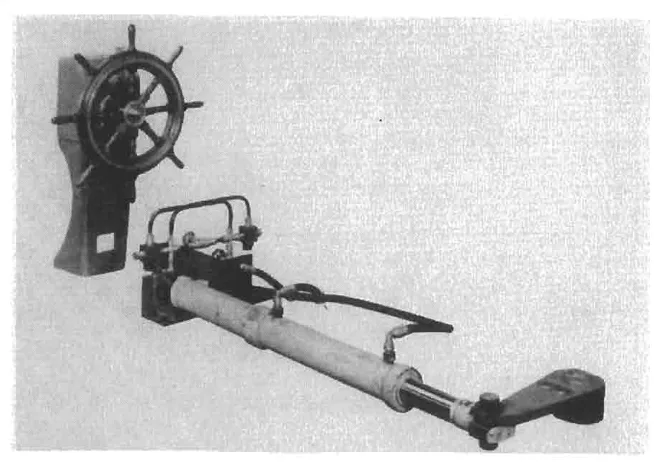
The components
The rams (U) in the double-acting steering cylinders G, which are free to oscillate on chocked trunnions, are linked directly to the tiller.
F is a double-acting control cylinder, linked to the floating lever V by rod O. J is a directional control valve, linked to the mid point of the floating lever by a spring link Z. W is the cut-off link from tiller to floating lever. H is a locking valve and I a bypass valve.
The floating lever V is the same device described in Chapter 7: it has a control input (through the control cylinder F), a hunting input (through the cut-off link W from the tiller) and an output (the directional control valve J).
Steering by hand
Valves C, D and S are solenoid controlled. When not energized, C is open and D is closed to through flow but acts as a bypass between the ends of control cylinder F when solenoid S is closed. When the solenoids are energized, C is closed, D and S are open. J is only operative when steering by power.
When steering by hand, C, D and S are not energized. A pump B in the steering pedestal, coupled to the wheel, delivers fluid under pressure direct to the steering cylinders G, so moving the tiller in the sense and to the extent appropriate to the movement of the wheel. There is no hunting action.
The phrase there is no hunting action is the important one, and it explains how hand steering on this gear works. The pump in the pedestal is driven by the wheel itself, so the amount of oil delivered is set by how far the wheel is turned. The rudder follows the wheel directly, and when the wheel stops, the pump stops. There is no need for a hunting gear, because the pump cannot keep pumping once the wheel is released — the helmsman's own hand is the cut-off.
Changing to power
To change to power steering, the power pump is started and C, D and S are energized — that is, C is closed, D ceases to be a bypass and it connects the steering pedestal pump to the control cylinder F. S, now open, allows fluid to pass from the power pump to J, which now comes under the influence of the floating lever.
Steering-wheel movement now moves the piston in F, the floating lever pivots on its attachment to W, and J opens to allow the power pump to discharge to the appropriate ends of the steering cylinders G.
As the tiller moves, a hunting movement occurs, the cut-off link W acting on the floating lever, which, pivoting on its attachment to O, closes I and brings the gear to rest with the rudder at the angle required.
So in power mode the pedestal pump no longer drives the rams; it drives the control cylinder, which moves the floating lever, which operates the directional control valve, which lets the power pump drive the rams. The helmsman's effort now operates a control rather than the rudder, and the hunting action appears because the power pump needs one.
The changeover is entirely automatic in the sense that it is done by energising three solenoids — the operator starts the pump and throws a switch, and the circuit rearranges itself. That is a much better arrangement than one requiring valves to be turned by hand.
Local control and emergency steering on this gear
Rudder angle indicators, either mechanically linked or electrically powered, are fitted as required.
For local control, the ends of the control cylinder are made common by opening a bypass valve, and the control piston is moved by a hand lever (shown dotted) or, for example, by wheel, rack and pinion.
It will be seen that in the off-loaded condition, the pump discharge circulates through J.
Emergency steering is by relieving tackles, fitted when the rudder is locked by closure of the valves H.
The last sentence describes the last resort, and it is worth noting what it involves: relieving tackles are rigged to the tiller or the quadrant and the rudder is moved by hand, using the tackles as a lever. For that to be possible the rudder has to be unlocked, which means the locking valves H have to be opened — and the tackles have to be on board and in good order, which is a matter of the routine checks.
The simplest form
If hand steering only is required, the gear is reduced to tiller, cylinders and rams, locking and bypass valves, rudder indicator and steering pedestal with pump. A simple form of this gear for torques below 11 kNm is also built.
So there is a size ladder: below about 11 kNm a plain hand-hydraulic gear, below about 150 kNm a hand and power gear, and above that a full electro-hydraulic installation. The rules' thresholds in Chapter 1 sit inside this ladder, which is why the 120 mm and 230 mm rudder stock figures correspond to real changes in what kind of gear is fitted.
6. The hand pinion and the block and hawser
For less onerous rule requirements, a hand pinion drive (as shown in the diagram of the two-ram gear) or hand pumping may be acceptable.
A hand pinion is a gear train with a handwheel that drives the rudder quadrant directly through a pinion. It is a purely mechanical emergency drive, and it needs no hydraulics at all.
In the extreme case of emergency, a block and hawser arrangement could be rigged up.
A block and hawser is a purchase rigged from the rudder or the tiller to a strong point, so that the rudder can be hauled over by hand. It is the oldest emergency steering arrangement there is, and it is still mentioned in the manuals because there are situations in which it is the only thing left. Its inclusion is a reminder that the requirement is not for a particular mechanism — it is for the ability to steer the ship, by whatever means can be made to work.
7. The alternative power supply
The requirement is stated in Chapter 1: where the rudder stock is over 230 mm diameter at the tiller, an alternative power supply capable of operating the rudder must be provided automatically within 45 seconds, supplying the power unit, its control system and the rudder angle indicator, with a capacity of at least 30 minutes for ships of 10,000 gt and over and 10 minutes for other ships. What follows here is how that is arranged.
The three items the supply has to reach are worth separating. It is not enough to supply the pump motor: the control system has to come back too, or there is a running pump with nothing to tell it what to do; and the rudder angle indicator has to come back, or the bridge has a rudder it cannot see. A rudder angle indicator that failed with the main power would leave the bridge steering blind at exactly the moment it matters most.
The supply can be provided from the ship's emergency power supply, or from an independent source of power located within the steering compartment and dedicated for this purpose.
The second option is the better one in a sense, because it is independent of everything else: a dedicated battery or an independent generator in the steering flat, supplying only the steering gear. A failure elsewhere in the ship's electrical system cannot reach it.
The 30 minutes is not arbitrary. It is the time needed to get the ship out of the situation that caused the failure — to bring her up, to stop, or to get clear of a channel. Ten minutes for a smaller ship is the same reasoning applied to a smaller consequence.
Twin electrical equipments
On an all-electric gear the equivalent provision is made by duplication:
Many installations are provided with completely separate twin electrical equipments on to one quadrant. A changeover switch allows independent operation, and either equipment can be directly operated from a rheostat aft for hand emergency steering.
The electric circuit will be on the essential services emergency circuit, being battery operated or battery and emergency generator operated.
In addition, a spur gearing from poop to quadrant teeth can be provided.
The above conditions would serve to satisfy the most onerous rules applicable. Suitable spare gear for all essential parts would require to be supplied.
Three separate provisions, then, on a large all-electric gear:
- Twin electrical equipment with a changeover switch, so one set can fail.
- An after rheostat, so the gear can be steered from the flat.
- A spur gearing from the poop to the quadrant teeth, which is a purely mechanical hand drive and needs no electricity at all.
And the note about spare gear is a rule in itself: an emergency arrangement that cannot be repaired is not an emergency arrangement. A spare armature and field coil, carried on board, is what turns a failed machine into a repairable one.
8. Duplication as an emergency provision
The most common way of meeting the emergency requirement on a modern ship is not a separate emergency gear at all. It is a steering gear that is built with its own redundancy, so that the loss of one part leaves a working gear.
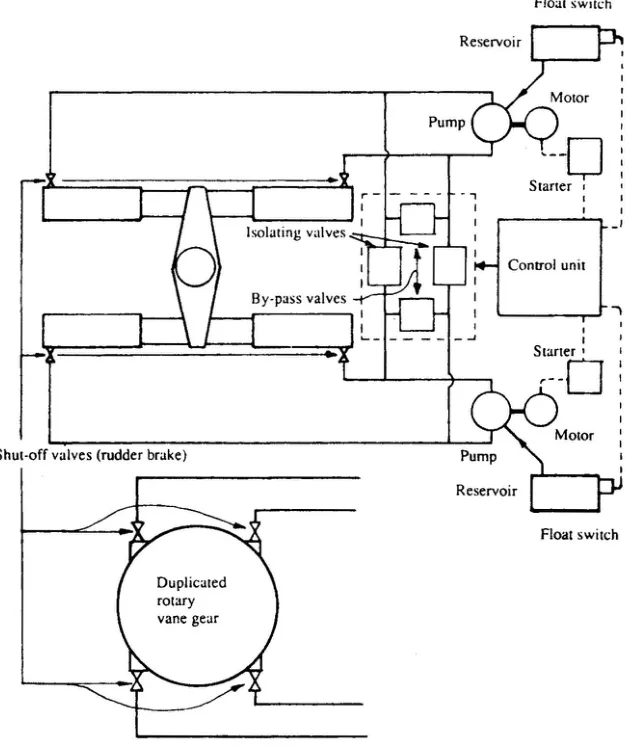
In many installations four rams are provided, two on each side of a double tiller arm, together with twin motor and pump units.
All connections are normally open, with one pump unit in service; the other is a stand by, which can be quickly switched on if the service motor fails.
During manoeuvring in dangerous waters both pump units are often used together.
Such installations are usually arranged to operate from emergency essential service battery and/or generator circuits in the event of a main power failure.
The above considerations satisfy the most onerous required regulations.
So one gear does four jobs at once:
- It is the main steering gear, with one pump running and four rams working.
- It has a standby pump, brought in by pressing a button, which covers a motor failure.
- It can run on two cylinders, which covers a cylinder or valve failure.
- It can run on the emergency supply, which covers a power failure.
And the duplicated hydraulic circuit — two separate circuits rather than one common one — covers the failure that matters most, which is the loss of oil from a fractured pipe. That arrangement, and the automatic isolation that goes with it, is the subject of Chapter 11.
9. Keeping the emergency arrangements real
Everything in this chapter is equipment that spends almost all of its life doing nothing, and equipment that does nothing decays. Four practices keep it usable:
Keep the changeover pin in the right hole. In port it goes in the hand position, and the wheels are lashed amidships. The instruction is specific because a pin in the wrong hole is indistinguishable from a pin in the right hole until the moment it is needed.
Keep the hand pump and the hand arrangements in condition. The hand pump needs oil in its reservoir, its valves free and its seals sound. The relieving tackles need to be on board, inspected and stowed where they can be found. The spur gearing needs to be greased and free to turn.
Keep the changeover instructions displayed in the steering compartment and on the bridge, and keep the officers familiar with them. The rules require this (Chapter 1), and the reason is that the changeover is done under pressure by whoever is nearest, who will not have time to read a manual.
Run the drill every three months, and log it. The drill is the only test these arrangements ever get, and a drill that reveals a seized handwheel, a missing pin or a flat emergency battery has paid for itself. The procedure is set out in Chapter 9.
The pattern behind all of it: every emergency arrangement on a steering gear is a mechanical device that somebody has to operate correctly, under time pressure, in a compartment they may not know well. The design does what it can — the single pin, the detent on the handwheel, the automatic changeover valve — but the rest is familiarity and drill.