
Rotary Vane Steering Gear — Principle, Pressure Limit and Ram Comparison
The vane type gear, which does the same job as a two-ram gear by turning the rudder stock directly instead of pushing a tiller.
Key Principles at a Glance 6 points
- The vane gear is compact: no tiller, no Rapson slide, no cylinder feet and guide beams — the gear is a ring around the stock and takes up much less of the steering flat.
- It is simple, with fewer moving parts than a ram gear, and the pressure acts directly on the part that turns the rudder.
- It is limited in pressure and therefore in torque — about 90 bar working against 170 bar or more on a ram gear — and the limit cannot be lifted because it comes from the shape of the component.
- It is more dependent on its hydraulics: with no mechanical lever to attach to, a vane gear cannot be driven by hand the way a ram gear can.
- The choice between the two is made by rudder torque — below a certain size the vane gear is the better answer, and above it the ram gear is.
- The angles available, the sealing arrangement and the vertical clearance are the details that decide how well a particular vane gear performs.
1. What it is
The vane unit is designed for a maximum pressure, and that figure is set by the sealing arrangement. The relief valve setting on a vane gear is not to be raised to get more torque out of it.
Vane type gears may be regarded as equivalent to a two-ram gear, with torque capacities depending on size. An assembly of two rotary vane gears, one above the other, provides the security of a four-ram gear.
Those two sentences place the vane gear exactly. In capability it is a two-ram gear: it can be built to a range of torques, and it is a single actuator with the same single-failure characteristics as a two-ram gear. And it is made redundant in the same way: stack two of them on the same stock and you have the equivalent of a four-ram gear.
The essential difference is mechanical. A ram gear converts a straight-line push into rotation through a tiller and a Rapson slide (Chapter 3). A vane gear converts hydraulic pressure directly into rotation, with no intermediate linkage at all — and that difference accounts for everything good and bad about the design.
2. The principle
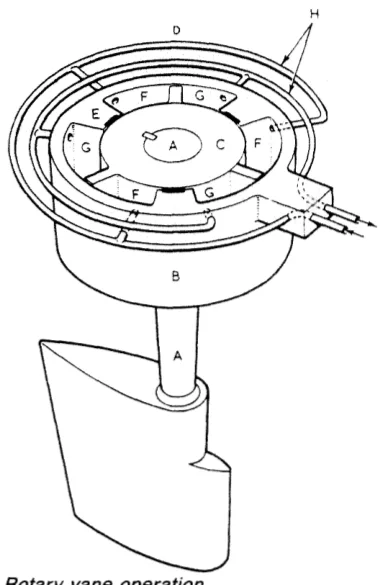
The rotor C is fitted and keyed to a tapered rudder stock. The stator B is secured to the ship's structure.
Fixed vanes, secured equidistantly in the stator bore, and rotating vanes, secured equidistantly in the rotor, form two sets of pressure chambers in the annular space between the rotor and stator. They are interconnected by a manifold.
Fluid supplied at pressure to one set of these chambers will rotate C clockwise and the rudder will turn to port, or to starboard if the alternate set is put under pressure.
The action is exactly like a rotary actuator: pressure in one set of chambers pushes the vanes round, and pressure in the other set pushes them back. There is no lever arm, no slide, no crosshead — the pressure acts on the vane and the vane is bolted to the rotor, and the rotor is keyed to the stock.
The angles available
Three fixed and three moving vanes are usual, and permit a total rudder angle of 70° — that is, 35° in each direction.
The movement obtainable from a gear with two fixed and two moving vanes may be 130°.
The three vane type is used for rudder angles of 70°, and for larger angles a two vane unit would be used.
The geometry is simple and worth understanding. The vanes act as stops for each other: a rotating vane can only travel until it meets a fixed vane. With three of each, each rotating vane has 60° of the circle to travel in, and the total rudder angle is twice that because the rotor can go either way from mid position. With two of each, each vane has 65° to travel in and the total is 130°.
So the number of vanes is a direct trade: more vanes means more torque-producing surface but less angle; fewer vanes means more angle but less torque. Since the rules require 35° each way (Chapter 1), three vanes is the natural choice for a ship's rudder, and a two-vane unit is only needed where a larger rudder angle is wanted for some special reason.
3. Construction
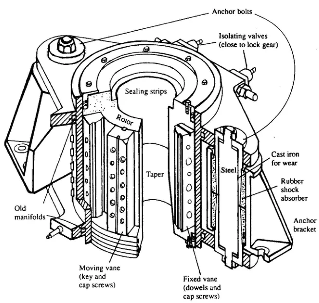
The vanes and how they are fixed
The fixed and rotating vanes may be of spheroidal graphite cast iron.
They are securely fixed to the cast steel rotor and stator by high tensile steel dowel pins and cap screws. Keys are also fitted along the length of the rotary vanes, for mechanical strength.
Assembly of the gear would not be possible if the fixed vanes were keyed; they rely on the dowels to provide equivalent strength.
That asymmetry is worth pausing on, because it is the sort of detail that reveals how the machine is built. The rotating vanes are both dowelled and keyed, because they can be — they are fitted to the rotor, which is a solid body that can have keyways cut in it. The fixed vanes cannot be keyed, because a keyway in the stator bore would have to be machined and the vane slid in along it, and there is no way to assemble that with the rotor in place. So the fixed vanes rely on dowels alone, and the dowels are sized to give the equivalent strength.
The vanes fixing is considered to be of sufficient strength to make them suitable to act as rudder stops.
This is an important point and it is unique to the vane gear. On a ram gear, the rudder stops are separate components — the telemotor stops, the external stops and the gear's own travel limits (Chapter 2). On a vane gear, the vanes themselves are the stops: a rotating vane cannot go past a fixed vane, and that is the mechanical end of the rudder's travel. The vane fixing therefore has to take the full shock of the rudder being driven against its stop, which is why it is dowelled and keyed so heavily.
The sealing arrangement
Steel sealing strips, backed by synthetic rubber, are fitted in grooves along the working faces of the fixed and rotary vanes, thus ensuring a high volumetric efficiency of 96 to 98 per cent, even at the relief valve pressure of 100 bar or over.
The sealing strips are what make the vane gear work at all. Without them, oil would leak past the vane tips from the high-pressure chambers to the low-pressure ones, and the gear would lose torque and drift. The synthetic rubber backing is the detail that makes the seal work: it is an elastomer behind the steel strip, so as the pressure rises the rubber compresses and forces the steel strip harder against the mating face. The seal gets tighter as the pressure rises, which is exactly the behaviour required.
A volumetric efficiency of 96 to 98 per cent is the measure of how well it works. Three per cent of the oil is slipping past, and that is the price of the design — but it is small enough that the gear still holds its rudder angle.
Anchoring and vertical clearance
Rotation of the stator is prevented by means of two anchor brackets and two anchor pins. The anchor brackets are securely bolted to the ship.
The stator has to be held still, and it is held by two brackets taking the whole of the gear's reaction torque. This is the vane gear's equivalent of the cylinder feet and stools of a ram gear.
Vertical clearance is arranged between the inside of the stator flanges and the top and bottom of the anchor brackets, to allow for vertical movement of the rudder stock.
This clearance varies with each size of the rotary vane unit, but is approximately 38 mm in total, and it is necessary that the rudder carrier should be capable of restricting the vertical movements of the rudder stock to less than this amount.
That last sentence is a direct link back to Chapter 2, and it is the most important operational point in this chapter. The vane gear is built with a defined vertical clearance for the stock, and the carrier bearing must keep the stock's movement within it. If the carrier bearing wears enough that the stock settles by more than that clearance, the stator flange and the anchor bracket come into contact, and the gear is being carried by its anchor brackets instead of by its bearing. That is why the rudder drop and the weardown allowance are checked on a vane-gear ship just as carefully as on a ram-gear one — arguably more so, because here the limit is a hard 38 mm rather than an allowance for the rams.
4. Pressure and its limit
The rotary vane unit is normally designed for a maximum pressure of about 90 bar, as distortion and leakage are liable to occur at higher pressures.
The vanes are considered suitable to act as rudder stops even at a relief valve pressure of 100 bar or over.
The two figures are worth reconciling. The 90 bar is the working design pressure; the 100 bar is the relief valve setting, which is set above the working pressure so that the relief valve does not lift in normal service. The gear works at up to 90 bar, and the relief valves protect it at around 100 bar and above.
Distortion and leakage are the reasons for the limit, and both follow from the geometry. A vane gear is a large-diameter annular pressure vessel with a rotor inside it, and as the pressure rises the stator distorts — it is a ring, and a ring under internal pressure does not stay round. As it distorts, the clearances open and the seals leak. This is not a manufacturing problem that better workmanship could solve; it is a consequence of the shape.
This is why the vane gear's pressure is limited to about half that of a ram gear. A ram cylinder is a small-diameter tube, which is an efficient pressure vessel; a vane gear is a large ring, which is not.
5. Comparison with the ram type
The manuals set out the comparison directly, and it is worth following because it explains why both types are still built.
Torque is dependent, for one actuator, on pressure, area and effective leverage.
The ram design is more adaptable to increase of these variables — and the reason is that it has three variables to work with. A ram gear's torque can be increased by raising the pressure, by enlarging the ram, or by lengthening the tiller. A vane gear has essentially only the first two, and the first is capped at about 90 bar.
Pressure is certainly limited on the vane type to about half that on rams, due to sealing difficulties.
Up to a certain torque the vane unit may well be smaller and lighter. However, integral design produces problems of construction, weight and size when the variables are increased.
So the vane gear wins at small sizes and loses at large ones. That is why it is common on smaller vessels and on ferries and specialist craft, and why large tankers have ram gears.
Provided alternative hydraulic pressure sources are available, emergency operation is readily achieved with either type, although the ram type is more flexible to alternative mechanical leverage.
That is the other important difference. A ram gear can be operated by hand pumping, by a hand pinion, or by relieving tackles on the tiller, because its input is a mechanical push on a lever (Chapter 8). A vane gear's input is hydraulic pressure into a chamber; if the hydraulics are gone, there is no mechanical lever to attach to. The vane gear is therefore more dependent on having a second hydraulic supply, and less amenable to being driven by hand.
Rudder support, and shock loadings, require more careful consideration with vane units, because of the very close and direct connection between rudder and actuator.
This follows from the absence of a tiller. On a ram gear, a shock load on the rudder is transmitted through the tiller and the Rapson slide, and the geometry of the slide and the relief valves absorb part of it. On a vane gear the rudder's shock load arrives at the vanes and the anchor brackets directly, with nothing in between to soften it. Hence the resilient mountings described in the next section, and hence the care taken over the rudder's support.
Finally, the apparent space and weight saving is not as great as may be imagined, due to the higher pressures and integrated construction utilised in modern hydraulic ram designs. There is however a definite space saving, but the first cost is usually higher.
A fair summary: the vane gear saves space, costs more, and saves less space than it looks as though it should once the modern ram gear is taken into account.
6. Support and shock absorption
Absorption and transmission of torque relief is essential, to avoid excess radial loading of the vanes.
This is the requirement that follows from the direct connection. A shock load arriving at the rudder has to be absorbed before it reaches the vanes, or it loads the vanes radially against the stator — a direction of loading the vane fixing was not designed for.
Support has resilient shock absorber mountings, which also allow for small misalignment.
The resilient mounting does two jobs: it absorbs shock, and it accommodates the small misalignments that inevitably exist between the rudder stock and the ship's structure. A rigid mounting would transmit both the shock and the misalignment straight into the gear.
Where spade type rudders are used, axial and radial thrust bearings are provided.
A spade rudder — one that is not supported at the bottom by a pintle or a skeg — imposes both axial and radial loads on the stock, and the bearings have to take both. That is the same distinction made in Chapter 2 between a rudder with pintle bearings, a hanging rudder and a Simplex rudder.
7. The control of a vane gear
The method of control for these gears, and also for the hydraulic supply system, is as described for electro-hydraulic gears.
That is a short sentence with a large content, and it is worth stating plainly: the vane gear changes the actuator, not the control system. Everything in Chapter 5 about variable delivery pumps, and everything in Chapter 7 about telemotors, hunting gear and electrical control, applies to a vane gear exactly as it does to a ram gear. The gear's input is a pair of hydraulic pipes from a variable delivery pump, and how those pipes are pressurised is a separate matter entirely.
The only difference in the hydraulic arrangement is that a vane gear has two ports rather than two cylinder connections — pressure to one set of chambers or the other — so there is no four-cylinder valve chest and no cylinder isolation to arrange. The duplication is achieved by stacking two vane units rather than by isolating cylinders.
8. What the vane gear gives you
Four things, and it is worth being clear about which of them are advantages and which are simply characteristics.
It is compact. No tiller, no Rapson slide, no cylinder feet and guide beams — the gear is a ring around the stock, and it takes up much less of the steering flat.
It is simple. Fewer moving parts than a ram gear, and the pressure acts directly on the part that turns the rudder. There is less to wear and less to maintain.
It is limited in pressure, and therefore in torque. About 90 bar working against 170 bar or more on a ram gear, and the limit cannot be lifted because it comes from the shape of the component.
It is more dependent on its hydraulics. With no mechanical lever to attach to, a vane gear cannot be driven by hand the way a ram gear can.
The gear that gets chosen for a particular ship is the one whose characteristics suit the rudder torque required. Below a certain size the vane gear is the better answer; above it, the ram gear is.