
Rudder: Construction, Types & Support
How a rudder is built, the balanced/semi-balanced/spade types, and how it is supported and prevented from lifting.
Key Principles at a Glance 6 points
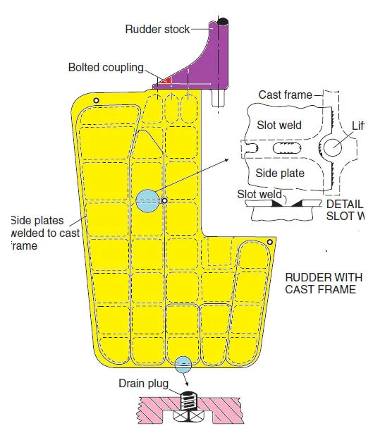
- A rudder allows the ship to turn; simple plates have been superseded by plates welded to a cast or fabricated frame, and rudders are hollow so they provide some buoyancy.
- Internal surfaces are given a protective coating and some rudders are filled with foam to minimise corrosion; a drain plug allows drainage, internal inspection (fibre-optic) and limited coating, plates are welded internally for flush fitting, and the final closing plate is welded externally.
- A means of lifting is provided, taking the form of a tube as close to the centre of gravity as possible, and rudders are tested to a pressure head 2.4 m above the top of the rudder.
- If the entire rudder area is aft of the stock it is unbalanced; a rudder with 20–40% of its area forward of the stock is balanced (there is an angle at which the resultant moment on the stock is zero), and most modern rudders are semi-balanced.
- A rudder may lift due to the buoyancy effect; the amount of lift is limited by the jumper bar fitted to the stern frame, and the jumper/rudder clearance must be less than the steering gear cross-head clearance to prevent damage.
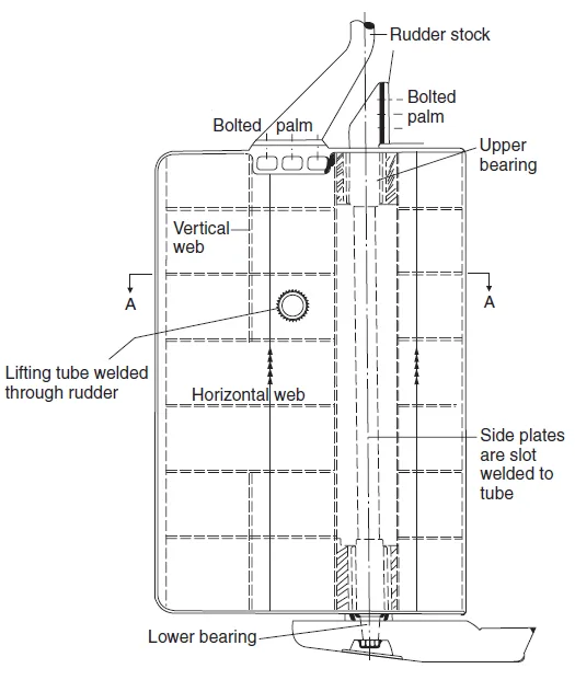
- A rudder is supported by a bearing pintle or a lower bearing depending on design; where a lower bearing is used, split bearing rings are fitted on the lower face of the rudder and the upper face of the sole piece (the extended lower stern frame section).
1. Rudder Construction
- A rudder allows the ship to turn. Simple plates have been superseded by plates welded to a cast or fabricated frame.
- Rudders are hollow and so provide some buoyancy.
- Internal surfaces are provided with a protective coating, and some are even filled with foam, to minimise the risk of corrosion.
- A drain plug is provided to allow drainage of water, enable internal inspection using a fibre-optic device, and even allow the limited application of a protective coating.
- Plates are welded to the frames internally to provide flush fitting; the final closing plate must be welded externally.
- A means of lifting is provided, taking the form of a tube as close to the centre of gravity as possible.
- Rudders are tested to a pressure head of 2.4 m above the top of the rudder.
The hollow body gives buoyancy (which reduces the load on the carrier bearing), but any water that leaks in must be drainable. The drain plug lets the surveyor drain and inspect the interior, and to apply a protective coating through the opening.
2. Balanced, Unbalanced & Semi-Balanced Rudders
- If the rudder has its entire area aft of the rudder stock, then it is unbalanced.
- A rudder with between 20% and 40% of its area forward of the stock is balanced, since there will be some angle at which the resultant moment on the stock due to the water force will be zero.
- Most modern rudders are of the semi-balanced design.
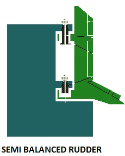
- Semi-balanced means that a certain proportion of the water force acting on the after part of the rudder is counteracted by the force acting on the forward half; hence the steering gear can be lighter and smaller.
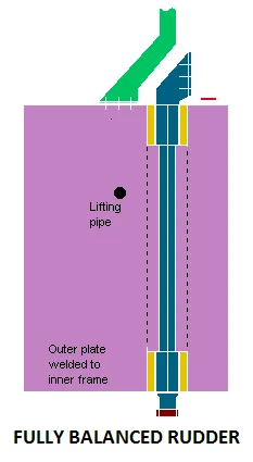
- A fully balanced rudder: to reduce the torque required to turn it, the pivot point is moved back from the leading edge; the torque then varies with the angle of attack, and zero torque leads to instability with the rudder moving within its clearances.
| Type | Area Forward of Stock | Characteristic |
|---|---|---|
| Unbalanced | 0% (all aft) | Highest steering torque |
| Balanced | 20–40% forward | Zero resultant moment at some angle |
| Semi-balanced | Lower portion forward | Most modern; lighter, smaller steering gear |
| Fully balanced | Pivot moved back | Zero-torque instability within clearances |
When part of the rudder is ahead of the stock, the water force on that forward part creates a moment that opposes the moment from the after part. At the balance angle the two cancel, so the steering gear needs far less torque to hold or move the rudder.
3. Rudder Support & Lifting
- A rudder is supported by means of a bearing pintle or a lower bearing, depending upon the design.
- Where a lower bearing is employed, the rudder is actually supported on split bearing rings fitted on the lower face of the rudder and the upper face of the sole piece (the extended lower section of the stern frame upon which the rudder sits).
- A rudder may lift due to the buoyancy effect; the amount of lift is limited by the jumper bar (jumping stops) fitted to the stern frame.
- The jumper/rudder clearance must be less than the steering gear cross-head clearance to prevent damage.
Surveyor Clearance Answer — Four Numbers (Quick Ref):
When the surveyor asks "quote the rudder-system clearances", answer in this order — jump — slide — drop — pintle:
- Jumping clearance: 6 mm.
- Rapson slide clearance: 16–19 mm.
- Propeller drop: 1 mm per 160 mm of tail-shaft diameter.
- Pintle clearance: 1.1–3.3 mm.
Because rudders are buoyant, they tend to jump upward. The jumper bar caps that lift, and the jumping clearance must always be smaller than the clearance in the steering gear cross-head — so the rudder is stopped by the jumper bar before the steering gear is damaged.
4. Special Rudder Types
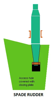
Spade Rudder:
- The reduced diameter at the upper part is purely to transmit torque.
- The lower section must also support bending moments and hence has an increased diameter.
- A spade rudder has no lower support, so the stock must carry the full bending load.
Twin Rudders:
- With twin-rudder ships the inner rudder must turn through a greater angle than the outer.
- This is achieved by having the tiller arm at an angle to the centreline of the rudder.
- It is possible to have the blades angled in or out when the wheel is amidships to increase propulsive efficiency.
Surveyors commonly ask: "Explain and draw the rudder." Give the construction (welded plates to a frame, hollow/buoyant, drain plug, 2.4 m test), the balanced vs unbalanced rule (20–40% forward), the support (pintle or lower bearing with split rings on the sole piece), and the jumper bar limiting lift. Mention spade and twin rudders.