
Variable Delivery Pumps — Hele-Shaw, V.S.G., Sunstrand and Hastie
The pumps that drive an electro-hydraulic steering gear.
Key Principles at a Glance 6 points
- Five designs are described — the Hele-Shaw, the V.S.G. Mark III and Mark IV, the slipper pad pump, the Sunstrand and the Hastie — and they are all the same idea in different clothes.
- Every one of them has a mid position in which it delivers nothing: the floating ring central, the tilt box vertical, the swashplate at zero.
- The amount of displacement from mid position sets the quantity delivered, and the side of mid position sets the direction of flow.
- Every one is controlled externally by a lever or a servo acting on a control spindle or servo valve, and that is where the steering gear's control system connects.
- Every one can be prevented from motoring when idle, by the non-reverse locking gear or an equivalent arrangement, which is what allows the duplication the rules require to be genuinely usable.
- A variable delivery pump is gentler than a constant delivery pump, and it is what lets the rudder start smoothly and stop where it was told.
1. Why a steering gear needs a variable delivery pump
The pump is set up to the maker's figures and its stroke is restricted externally. A pump that has been re-set to deliver more than the maker's maximum is a pump that has been re-set to overload the rudder stock.
Variable delivery pumps can run continuously in one direction but have the capability of an infinitely changeable discharge from zero to a maximum, either way.
Every word of that sentence is doing work, and it is worth unpacking:
- Run continuously in one direction — the pump motor never stops and never reverses. A steering gear motor that had to start, stop and reverse for every rudder movement would be worn out in a year, and it could not respond fast enough anyway.
- Infinitely changeable discharge — the flow can be set to any value between zero and maximum, with no steps. That is what gives a small rudder movement a small flow and a large movement a large flow.
- Either way — the flow direction reverses, so the same pump drives the rudder to port or to starboard.
The principle of operation is based on altering the stroke of the pump pistons in radial or axial cylinders, by means of a floating ring or swash plate respectively, to change the amount of oil displaced. That one sentence names the two families: radial pistons with a floating ring (the Hele-Shaw), and axial pistons with a swash plate or tilting box (the V.S.G. and its descendants).
Why it is gentler than a constant delivery pump
There is very little shock to the hydraulic system as the pump commences delivery, because the piston stroke increases from zero gradually. A constant delivery pump switched into a circuit by a valve applies full flow instantly, and the resulting pressure wave is felt through the whole system.
For a small rudder movement, piston stroke is small; the stroke becomes full only for larger rudder movements.
At the end of the rudder movement, pump discharge tapers off; it does not cease abruptly, as with constant delivery pumps which have valve control.
The consequence is a gear that starts and stops smoothly and holds its rudder angle precisely. That is not a refinement — it is the reason the variable delivery pump is the standard for steering gears, and it is what makes the hunting gear's cut-off work as well as it does.
2. The radial cylinder (Hele-Shaw) pump
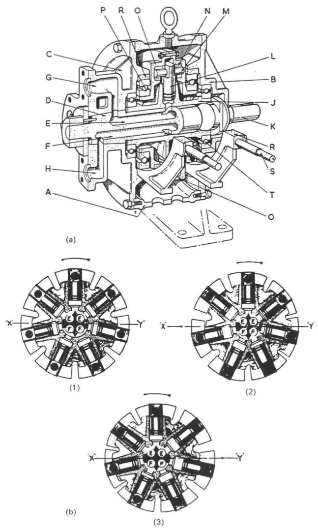
The Hele-Shaw pump is the radial piston design. Its construction is worth following in detail, because the lettered key appears on the diagrams and because the arrangement is unlike anything else on the ship.
The construction
The pump consists of case A, to which are attached two covers — the shaft cover B and the pipe connection cover C.
The pipe connection cover C carries the D tube (or central valve), which has ports E and F forming the connections between the cylinders and branches G and H. The D tube is the fixed central member. It does not rotate; the cylinder body rotates around it. The ports in it are the suction and discharge ports, and because the tube does not rotate, the ports are stationary in space — which is exactly what is needed for oil to be drawn in on one side and discharged on the other.
The cylinder body J is driven by shaft K, and revolves on the D tube, being supported at either end by ball bearings T.
The pistons L are fitted in radial cylinders, and through the outer end of each piston there is a gudgeon pin M, which attaches the slippers N to the piston. The gudgeon pin is the joint that lets the slipper follow the ring while the piston moves in and out.
The slippers are free to oscillate on their gudgeon pins and fit into tracks in the circular floating ring O.
This ring is free to rotate, being mounted on ball bearings P, which are housed in guide blocks R. The floating ring rotating is the refinement that distinguishes a good Hele-Shaw from a crude one: because the ring can turn, the slippers are not scrubbing round a stationary track, and the churning and friction losses are much reduced.
The guide blocks R bear on tracks formed on the covers B and C, and are controlled by spindles S, which pass through the pump case A. The spindles are the control connection — this is where the steering gear's control system gets hold of the pump.
The maximum pump stroke is restricted by the guide block ends coming in contact with the casing. Further restriction of the pump stroke is effected externally. Two limits, therefore: a hard mechanical limit inside the pump, and a settable external limit. The external one is what the maker sets to suit the particular gear, and it is the one that must not be tampered with.
How the pumping action is produced
The sections at right angles to the axis show the D tube, the cylinder body, the pistons and the slippers. XY is the line along which stroke variations take place.
There are three cases:
1. With the floating ring central — that is, concentric with the D tube — the slippers move round in a circle concentric with the D tube, and consequently no pumping action takes place. The pistons are simply going round; they are not moving in and out relative to the tube.
2. With the floating ring moved to the left — the slippers rotate in a path eccentric to the D tube and cylinders; consequently the pistons, as they pass above the line XY, recede from the D tube and draw oil through the ports E, whilst the pistons below XY approach the D tube and discharge oil through ports F.
3. With the floating ring moved to the right — the reverse action takes place: the lower pistons moving outwards draw oil through ports F, and the upper pistons moving into the cylinders discharge oil through ports E.
The direction of flow therefore depends on the location of the floating ring, left or right of the centre. The floating ring can be moved to any intermediate position between the central and maximum positions, and the quantity of oil discharged varies according to the amount of displacement of the floating ring from its mid-position.
That is the whole of the variable delivery principle, in three cases and a continuous range between them. Position of the ring = quantity; side of centre = direction.
The same principle described from the other end
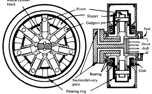
There is a second way of describing the Hele-Shaw action, and it is worth having because it is easier to picture. In this account the shaft is stationary and the cylinder body forming the cylinders rotates around it, being driven by a constant speed and direction electric motor. The plungers are connected to slippers which run in annular grooves inside two circular rings on each side of the plungers.
When the centre of the rings coincides with the shaft centre O, the pump travel is at mid position. At this position the plungers rotate at a fixed radius from the shaft centre, there is no relative motion between the plungers and the shaft, and no pumping action takes place.
If the circular slipper rings are moved to the right by the operating rod, through the casing from the telemotor rod, then the centre of rotation of the slippers and plungers is at B, which is eccentric to the centre of the shaft O. The greatest distance the plunger gudgeons are from O is OG and the shortest distance is OF. In travelling round from G to F the plungers are moving in relative to the fixed central shaft and ports, hence the top port T acts as a discharge. In completing the circular route from F back to G the plungers are moving out relative to the central shaft and ports, and the bottom port B acts as a suction.
If the rings are moved left, so the centre of plunger rotation is at A, then the shortest distance is OD and the greatest distance is OE — the plungers are moving out in the top half of rotation, so T is a suction and B is a discharge. The direction of flow is reversed by moving the ring to the other side of centre.
The circular rings are not rigidly fixed but are free to rotate as floating rings on roller bearings, which reduces oil churning and friction losses. The control or actuating spindle passes through the casing and moves the floating ring horizontally left or right by means of the floating ring guide on horizontal slides.
In practice the pump is usually provided with an odd number of cylinders, usually seven or nine, which produces more even hydraulic flow and better pump balance. The odd number is not arbitrary: an odd number of pistons means that the discharge pulses interleave rather than coinciding, so the flow is smoother and the reaction on the bearings is better balanced.
3. The swash plate axial cylinder pump — the V.S.G.
The axial piston design takes the opposite approach: instead of pistons arranged radially around a shaft, the pistons are parallel to the shaft and their stroke is produced by tilting the plate they bear against.
The original Mark III arrangement
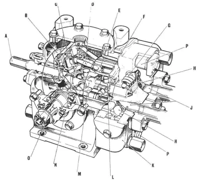
The pump has a circular cylinder block with axial cylinders disposed on a pitch circle around a central bore, which is machined with splines to suit the input shaft with which it revolves.
The individual cylinders are parallel with the shaft, with one end of each terminating in a drilled port at the end face of the block. This face bears against a stationary valve plate and is maintained in contact by spring pressure. The spring compensates automatically for wear.
Semi-circular ports in the valve plate, in line with those from the cylinders, are connected by external pipes to the steering cylinders. The valve plate is the distribution member: as the block rotates, each cylinder's port passes over the suction arc and then the discharge arc of the valve plate.
The connection is often direct to the cylinders for two-ram gears, but by way of a change-over valve chest in four-ram gears. That is the same valve chest described in Chapter 4.
In the Mark III design, the cylinder barrel is driven by the input shaft through a universal joint, and the valve plate contact springs are supplemented by hydraulic pressure. The hydraulic assistance is what makes the design work at higher pressures: spring pressure alone is not enough to keep the face sealed when the pressure is high.
Each cylinder contains a piston, connected by a double ball-ended rod to a socket ring driven by the input shaft through another universal joint and rotating on roller thrust bearings — in some cases on Michell pads — within a tilt box. This is carried on trunnions and can be tilted on either side of the vertical by an external control — the telemotor, for a steering gear.
When the tilt box is vertical, the socket ring, cylinder barrel and pistons all revolve in the same plane and the pistons have no stroke. As the box is tilted, and with it the socket ring, stroke is given to the pistons at each half revolution, the length of stroke being determined by the angle of tilt.
So the V.S.G. achieves the same three properties as the Hele-Shaw — no stroke at mid position, variable stroke by amount of displacement, reversed flow by displacing to the other side — using a different geometry. Position of the tilt box = quantity; side of vertical = direction.
The Mark IV
The V.S.G. pump has been developed in recent years to operate with higher pressure, with a resulting decrease in size of steering gears. The unit accordingly has a casing of fabricated steel rather than cast iron.
The cylinder block with its pistons is driven through the drive shaft by a simple constant-speed electric motor. The pistons are tied through piston rods and bearings to a swash plate or tilting box. With the latter vertical, the pistons rotate with the cylinder block but have no axial movement. When the swash plate or tilting box is set at an angle by the controller, the pistons are caused to reciprocate in their cylinders and produce a pumping action.
Stepless changes of pump delivery from zero to maximum in either direction are achieved through lever or servo controls.
The move from cast iron to fabricated steel is the same story as everywhere in machinery: higher pressure needs a stronger, more reliable casing, and a fabrication gives that without the risk of a casting defect in a highly stressed part.
4. The slipper pad axial cylinder pump
This is another development of the pump described above, suitable for the higher pressures demanded as steering gear and fin stabiliser systems were developed.
The socket ring and connecting rods are replaced by slipper pads in the tilt box, the spherical ends of the pistons being carried in the pads.
Inclination is given to the tilt box by a servo piston, which is operated by hydraulic pressure.
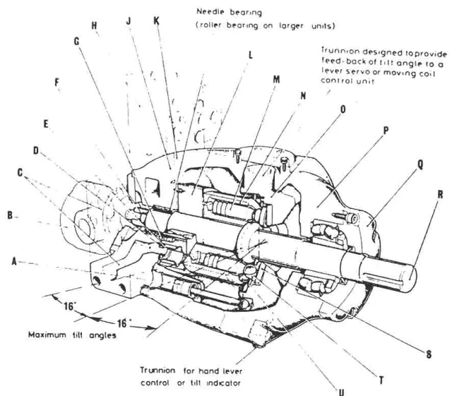
The change from a socket ring and ball-ended rods to slipper pads is a change from a linkage to a sliding contact. A slipper pad carries a much higher load than a ball-ended rod, which is why the design appears as the pressures rise.
5. The Sunstrand pump
Another variant is the Sunstrand pump, in which a reversible swashplate, vertically disposed and given the desired angular rotation by an integral servo-piston, is used to vary the quantity and direction of the hydraulic fluid.
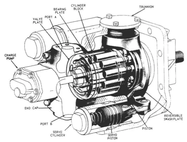
The distinguishing feature is that the servo piston is integral to the pump. On the other designs the control mechanism is a separate assembly that acts on the pump's control spindle; here it is built in. That makes a more compact unit and a more direct control, at the cost of making the pump's control mechanism part of the pump rather than a separate maintainable item.
6. The servo-controlled axial cylinder pump — the Hastie
This pump is the high-pressure end of the family, and it is described in enough detail in the manuals to be worth following, because it shows what a modern servo-controlled pump consists of.
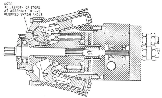
Variants of the servo-controlled swash plate axial cylinder pump are capable of working at 210 bar. Each pump is complete with its own torque motor, servo-valve, cut-off mechanism, shut-off valve and oil cooler.
A complete package, then: the pump, its control, its protection and its cooling. These pumps are brought into operation as described earlier, and an idle pump is prevented from motoring.
What it is made of
The rotating assembly of the pump — which consists of cylinder, nine pistons, valve plate, slippers, slipper plate and retaining ring — is manufactured from ENS steel, which is finally machined, heat treated and then hardened for long wear.
The nine pistons are fitted with return springs. The return springs pull the pistons back off the swashplate on the suction stroke, so the pump does not rely on hydraulic pressure to retract them.
The casing and covers are of nodular cast iron. Nodular cast iron is used where a casting is wanted but the strength of a casting is not enough on its own — it is ductile, so it resists shock loading.
The main valve block is of ENS steel and houses five check valves, the main pump relief valve, the boost and servo-relief valves, the boost gear pump and the servo gear pumps.
That is a lot of functions in one block, and it is the same principle as the steering gear's valve chest in Chapter 4: gather the valves where the pipes meet, rather than distributing them around the machine.
Piping from the valve block supplies the servo pistons via the servo valve.
The main drive is through a splined shaft to the cylinder body. A splined shaft rather than a key, because the torque is large and a spline spreads the load over many teeth.
How it is controlled
The pump swash plate is actuated by two servo cylinders, which receive oil at the desired pressure through a directional servo-valve. The servo-valve is displaced initially by the torque motor acting on the input signal demand, and is returned to the neutral position by the hunting linkage connected to the swash plate.
So there are two feedback loops, one inside the other:
- The outer loop is the steering gear's own — the bridge asks for a rudder angle, and the rudder angle feedback cancels the demand when it is reached. That is described in Chapter 7.
- The inner loop is inside the pump — the torque motor asks for a swash plate angle, and the swash plate angle feedback returns the servo-valve to neutral when it is reached. That is the hunting action of the pump.
The hunting action is achieved through the application of a simple lever system connecting input and displacement servo-valve and the hunting action from the pump swash plate angle. This allows for a very fast response.
The fast response is the point of the inner loop. The pump does not wait for the whole steering gear to respond before it stops changing its stroke; it corrects its own stroke immediately, and the outer loop handles the rudder angle. Two nested control loops, each correcting its own variable.
The control system that drives the torque motor is described in Chapter 7.
7. The non-reverse locking gear
There is a problem that appears as soon as a gear has two pumps, and it is easy to miss.
When two pumping units are fitted and only one is running, the idle pump might be driven in the reverse direction by fluid under pressure from the running pump, if non-reverse locking gear were not fitted.
An idle pump connected to a live circuit is a motor. The live pump's discharge pressure would spin the idle pump's cylinder body backwards, which at best wastes power and at worst damages the pump and unloads the system.
This gear is integral with the flexible coupling connecting motor and pump.
It consists of a number of steel pawls so mounted on the motor coupling that, when pumping units are running, they fly outward due to the centrifugal effect and remain clear of the stationary steel ratchet secured to the motor supporting structure.
The limit of this outward movement is reached when the pawls contact the surrounding casing, which revolves with the coupling.
When the pumps stop, the pawls return to their normal, inward position and engage the ratchet teeth, so providing a positive lock against reverse rotation.
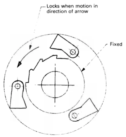
This action is automatic, and permits instant selection and commissioning of either unit without needing to use the pump isolating valves, which are normally open — and are only closed in an emergency.
That last point is the operational value of the device, and it is worth stating separately: because the idle pump cannot be driven backwards, the pump isolating valves can be left open. The standby unit is therefore always connected and always ready, and bringing it into service is a matter of pressing a start button. Without the locking gear, the isolating valves would have to be shut on the idle unit, and the changeover would become a valve operation performed under pressure — exactly what you do not want to be doing when the ship needs steerage.
The same device appears in another form: a centrifugal coupling between motor and pump, whose pawls open out when running but when stopped the pawls engage a ratchet so locking against rotation. Same principle, packaged as the coupling itself.
8. The constant delivery pump as an alternative
A steering gear, as with any hydraulic system, can be operated by a constant delivery pump as an alternative to the conventional variable delivery type. Output from the pump, which runs continuously, is circulated through a bypass until required for steering gear movement.
The constant delivery pump is simpler and cheaper, and it is used on small gears. It works by dumping its whole output through a bypass when no rudder movement is wanted, and directing it to the rams when movement is wanted. The disadvantages follow directly from that: the oil is being pumped and dumped continuously, so the system runs hotter and wastes power, and the transition from bypass to working is abrupt.
The small hand-and-power steering gear built on this principle is described in Chapter 8.
9. What the pumps have in common
Five designs have been described — the Hele-Shaw, the V.S.G. Mark III and Mark IV, the slipper pad pump, the Sunstrand and the Hastie — and they are all the same idea in different clothes.
Every one of them has a mid position in which it delivers nothing. The floating ring central, the tilt box vertical, the swashplate at zero — all the same condition.
Every one of them varies its delivery by displacing that member from mid position. Amount of displacement sets the quantity.
Every one of them reverses its flow by displacing that member to the other side of mid position. Side of centre sets the direction.
Every one of them is controlled externally, by a lever or a servo, acting on a control spindle or a servo valve. That is where the steering gear's control system connects, and it is the subject of the next chapter but one.
And every one of them can be prevented from motoring when idle, by the non-reverse locking gear or by an equivalent arrangement. Which is what allows the duplication the rules require to be genuinely usable.