
Steering Gear Control Systems — Telemotor, Hunting Gear and Floating Lever
How an order given on the bridge becomes a rudder movement, and how the rudder is stopped at exactly the angle ordered.
Key Principles at a Glance 6 points
- Six things have to go right, and each of them is a way the control system can fail: the order must arrive, be interpreted in the right sense, start smoothly, stop at the angle ordered, hold the rudder there, and be correctable by the person on watch.
- A broken pipe, a broken wire or a seized linkage is enough to lose the order, because the control path is long and it runs through places nobody looks at.
- A control connected backwards steers the ship the wrong way, and the rudder angle indicator is what shows it.
- The variable delivery pump is what makes the gear start smoothly and stop at the angle ordered, and the hunting gear is what makes it stop there at all.
- Take the hunting gear away, leave it disconnected or let it go out of adjustment and the gear becomes an open-loop remote control that will drive the rudder hard over and keep it there.
- Every control system in this chapter, hydraulic or electrical, mechanical or electronic, has a feedback path from the rudder — and the feedback is the control system.
1. What the control system has to do
The control system is what the ship is actually steered by, and it is the part most often found defective. A control system that has been adjusted to make it work is a control system that has been adjusted out of the maker's specification.
The steering gear is a large, powerful machine located at the stern of the ship. The person steering is on the bridge, perhaps two hundred metres away. The control system is the whole of the connection between them, and it has three jobs:
- Carry the order from the bridge to the steering gear.
- Start the gear moving in the right direction, and by the right amount.
- Stop the gear when the rudder arrives at exactly the angle ordered — and hold it there.
The third job is the one that distinguishes a steering gear control system from a simple remote control. Any linkage can move a lever at the far end. What a steering gear needs is a system that knows when to stop, and the device that provides that knowledge is the hunting gear.
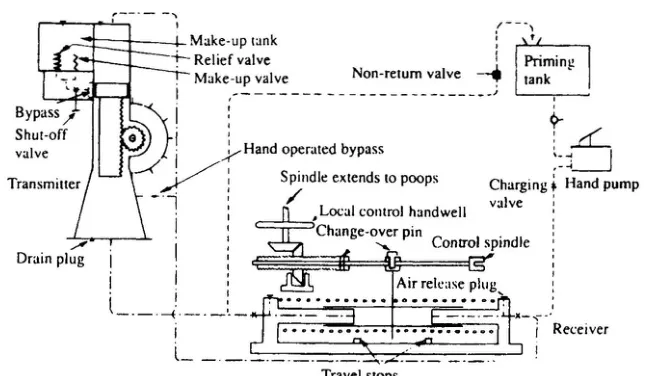
The telemotor employs a master and slave principle. The transmitter is situated on the bridge and the receiver at the steering gear unit. Mechanical movement is transduced hydraulically or electrically for distance telemetering, and then transduced back again. The steering wheel may be retained as an ornament — on a modern ship the wheel on the bridge often has no mechanical connection to anything at all, and the control is by a small lever.
The gears described in this volume — electro-hydraulic and electrical — when operated by auto-pilot, illustrate fundamental closed-loop control principles. That is a useful way to think about the whole subject: the control system is a closed loop, and the hunting gear is its feedback.
2. The hydraulic telemotor
The telemotor has become, on many vessels, the stand-by steering control mechanism, used only when the electric or automatic steering fails.
It comprises a transmitter on the bridge and a receiver connected to the steering gear variable delivery pump, through the hunting gear. Transmitter and receiver are connected by solid drawn copper pipes. Liquid displaced in the transmitter causes a corresponding displacement in the receiver, and movement of the pump control through the hunting gear.
The hydraulic telemotor is a simple and elegant device: two pistons in cylinders, connected by pipes full of oil. Push one piston in, and the other comes out by the same amount, because the oil is effectively incompressible. No electricity, no electronics, no power supply — just oil in pipes. That is why it survives as the emergency system long after it has ceased to be the normal one.
Hydraulic telemotors, where fitted, should be regularly checked, however, with any leak being made good and the oil topped up.
The problem with changing over
There is a warning in the history of the telemotor that is worth knowing, because it is a control system failure that has caused a collision.
Some problems were experienced with the early versions of automatic steering systems when changing from automatic to manual steering and vice versa. An incorrect change over was blamed for at least one collision — the change over involved a hydraulic telemotor system, the by-pass for which had not been correctly set.
The failure is instructive: nothing was broken, and no component failed. The changeover was simply done wrongly, and the bypass valve was left in a state that made the control ineffective. That is why the rules require the changeover instructions to be displayed in both the steering compartment and on the bridge (Chapter 1), and why the three-monthly drill exists (Chapter 9).
3. The transmitter
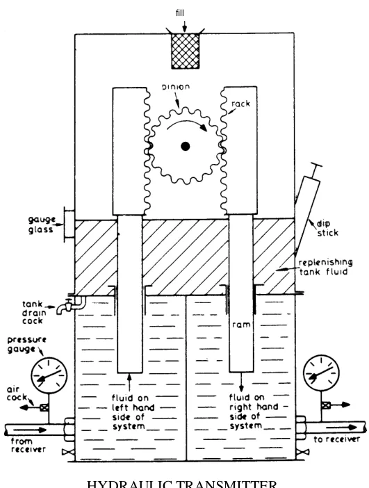
The transmitter consists of a cylinder with a pedestal base, which contains a piston operated by a rack and pinion from the steering wheel.
The make-up tank functions automatically through spring loaded relief and make-up valves.
Excess pressure in the telemotor system causes oil to be released through the relief valve to the make-up tank, and loss of oil is made up through the lightly loaded make-up valve.
Those two valves are a matched pair doing opposite jobs, and the pressures they are set at explain why:
- The relief valve is spring loaded, so it opens only when the pressure is high, and it lets oil out to the tank.
- The make-up valve is lightly loaded, so it opens whenever the pressure on the system side falls even slightly below the tank, and it lets oil in.
The result is a system that is self-regulating in volume. As the oil warms and expands, the pressure rises and the relief valve releases the excess to the tank. As the oil cools and contracts, the pressure falls and the make-up valve lets oil back in. The system is never over-pressured and never draws in air.
The two valves are connected through a shut-off valve, which is normally left open, and the bypass which connects both sides of the pressure system when the piston is in mid position. There is also a hand operated bypass.
The tank must be kept topped up.
How the transmitter displaces oil
The action is worth following in the physical detail, because it explains the bypass valve in the next section.
As the bridge steering wheel is moved to starboard, the rotating pinion causes the right hand ram to move down, pushing oil out to the receiver unit along the right hand pipe. The left hand ram moves up, so allowing a space for oil to come from the receiver unit.
The fluid is virtually incompressible, hence any down movement of the right hand ram produces an identical movement at the receiver unit. This in turn displaces the same quantity of fluid, which is taken up in the extra space created by the left hand ram moving up. The fluid in the replenishing tank acts as an oil reservoir.
So the transmitter is a double-acting device: one ram pushes oil out while the other draws oil in, and the same happens at the receiver. The circuit is a closed loop of oil, and the volume of oil in it never changes as long as the system is sealed. That is what makes the transmitter and receiver move in step.
The casing is usually gunmetal, with bronze rams, and copper pipes are led in by drilled leads in the casting. Gunmetal for the casing and bronze for the rams, because these are bearing surfaces sliding in each other; copper pipes because copper does not corrode in this service and is easy to bend into the runs required.
Some device is required in the system to allow for variations in oil volume due to temperature changes, and also to allow for equilibrium between both sides of the system. That device is the bypass valve.
4. The bypass valve
The device is called the bypass valve, which has the additional functions of topping up the system in the case of leakages and acting as a relief valve in case of pressure rise.
Three functions in one small component, and they are all needed:
- Equalising the two sides of the system so that the receiver can be brought back to midships.
- Topping up after a leak.
- Relieving excess pressure caused by the oil expanding.
How it is operated
Operation can only be carried out when the wheel is in the mid position. This is achieved by having the operating rod butting against a circular disc; in mid position of the wheel, the slot in the driven revolving disc allows the operating rod to be depressed through it.
That is a mechanical interlock, and it is essential. If the two sides of the system were connected while the wheel was off midships, the oil would flow from one side to the other and the rudder would go wherever the pressure took it. By making the bypass operate only at mid position, the interlock guarantees that the equalisation happens at a moment when equalising does no harm.
With some types the operating rod is depressed by hand, whilst with other types the rod is automatically depressed by a cam each time the wheel passes mid position.
In the case of the former, the rod is operated at regular intervals, and must be operated when either pressure gauge registers above 4.5 bar, with the wheel at mid position.
The 4.5 bar figure is the instruction to the operator: if the telemotor's pressure gauges are reading above that, the oil has expanded or the system has taken on pressure, and the bypass must be operated to equalise it. On the automatic type the cam does it every time the wheel passes midships, which is why the automatic arrangement is preferred — it does the job whether or not anyone remembers.
When the rod is depressed, both sides of the system are connected, so giving pressure balance. The connection to the replenishing tank is also joined to both sides of the system, so that any expansion or contraction of the oil can be corrected.
In some types a relief valve is fitted in the line to the replenishing tank, set at about 18 bar, and a replenishing valve, working in the opposite direction, is also provided, which is loaded at about 2.5 N. Other types employ direct piping to the replenishing tank with no valves.
The 18 bar relief and the 2.5 N replenishing valve are the same pair of functions as the transmitter's relief and make-up valves, but built into the bypass unit instead. The very light loading on the replenishing valve — 2.5 newtons is about a quarter of a kilogram — is what makes it open at the slightest drop in system pressure, so that air can never be drawn in.
5. The receiver
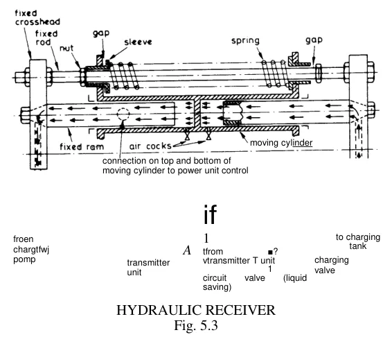
The section through the receiver shows two receiving cylinders in one casting, with circuit pipes connected to the outer end of each ram. Any fluid displaced in the transmitter cylinder by the piston will therefore be forced through the pipes and circuit valve to the receiving cylinder.
The receiver rams are fixed in the arrangement shown, and any displacement of the fluid causes the cylinder body to move along the rams, against the compression of one of the springs.
That reversal — the rams fixed and the cylinder moving — is the neat part of the design. At the transmitter the piston moves and the cylinder is fixed; at the receiver the cylinder moves and the pistons are fixed. It makes no difference to the hydraulics, and it means the receiver's output is a moving body that can carry a linkage.
The compressed spring serves to return the receiver, and with it the transmitter, to midship position when the helmsman releases the steering wheel.
This is the self-centring behaviour, and it is a safety feature. If the helmsman lets go of the wheel, the rudder returns to midships and the ship steers straight. It is also what makes the wheel's position mean something: the wheel is spring-centred at midships just as the receiver is.
The linkage to the pump control through the hunting lever is fitted to one end of the cylinder body.
How the receiver follows the transmitter
Considering the starboard movement of the bridge wheel, the depressed right hand ram pressurises the right hand side of the system. The pressure force acts on the central web of the moving cylinder until the movement caused corresponds to the movement of the ram in the steering telemotor. Oil is pushed back on the left hand side of the moving cylinder central web to the steering unit.
After a small initial movement, the left hand sleeve butts against the nut, and further movement by the moving cylinder to the left compresses the springs.
The free movement before the spring is engaged is deliberate: it gives a small amount of lost motion, which is what stops the receiver being a rigid connection. A rigid receiver would transmit every shock on the rudder straight back to the bridge wheel.
When the steering wheel is returned midships, the springs, which are under initial compression, return the moving cylinder to mid position.
For a port wheel rotation, the left hand ram of the steering unit moves down, and the receiver moving cylinder goes in the opposite direction.
Together with the bypass valve, the springs form the adjusting, centralising device.
The moving cylinder is connected by a linkage to the control unit of the steering engine. Thus any movement of the bridge telemotor unit by wheel rotation is almost directly opening the control device, which causes rotation of the steering engine and rudder movement.
The stops
Centring springs are fitted to bring the cylinders to mid position. Movement of the telemotor receiver is limited by the stops set at 35°.
Those are the stops that impose the 35° rudder limit referred to in Chapter 2. The telemotor's travel is limited, and the helmsman therefore cannot ask for more than 35°. It is a control limit rather than a mechanical one, which is why it is the right place to have it: the gear never reaches its own hard stops in normal service.
6. The telemotor fluid
Good quality mineral lubricating oil is used, with the following properties:
- Low pour point.
- Non sludge forming.
- Non corrosive.
- Good lubricating properties.
- High flash point.
- Low viscosity, to reduce frictional drag, but not too thin to make gland sealing difficult.
Typical properties would be: density 880 kg/m³ at 15.5 °C, viscosity 12 cSt at 50 °C, closed flash point 150 °C, pour point −30 °C.
The low pour point is the property that matters most, and it is why the rules require a non-freezing fluid (Chapter 1). A telemotor is a thin pipe run from the bridge to the stern, and in a cold climate the fluid in those pipes will reach the ambient temperature. Fluid that has thickened or frozen cannot transmit movement, and the ship cannot be steered from the bridge.
The viscosity requirement is a balance: low enough that the fluid flows easily and the drag on the wheel is small, but not so low that it leaks past the glands. 12 cSt at 50 °C is a light hydraulic oil.
Before the general use of mineral oil, it was common to employ a mixture of glycerol and water as the low pour point (non-freezing) working medium. Glycerol and water was the original antifreeze hydraulic fluid, and it worked; mineral oil replaced it because it also lubricates the glands and does not evaporate.
7. Charging the telemotor
The telemotor must be full of oil and free of air, and filling it is a definite procedure with a definite order.
The system is provided with a priming tank and hand pump, which are situated in the steering gear compartment.
When charging, the shut-off between the make-up tank and transmitter is closed, and the wheel is brought to the mid position, so that the piston is at the centre of its travel and the top and bottom parts of the cylinder are connected through the bypass.
The priming tank is filled — and then kept topped up as necessary — and the hand pump operated with the charging valve open. Each section of the pipe is progressively filled, with air being released through the bleed screws.
At the last section the non-return valve is opened, to allow oil from the end of the pipe to be returned to the priming tank.
Pumping is continued for some time, then the non-return valve is closed while pressure is maintained with the pump. The bleed screw at the top of the cylinder is cracked open to get rid of any remaining air. After closing the bleed screw on the cylinder, the shut-off between the cylinder and make-up tank is opened, and the tank is brought up to level.
For an initial charge, pipes are disconnected so that the sections of pipe can be washed through.
During the charging operation, joints are checked for leakage, and when the system is full, a further check is made with the shut-off closed and pressure maintained with the pump. At this stage, if the non-return valve is opened, each stroke of the hand pump should produce a discharge back to the tank which exactly coincides with the movement of the pump lever.
That last check is a good one, because it is a direct test of whether the system is full. If the pump is delivering into a system with no air in it, the oil comes straight back to the tank at a rate matching the pump's stroke. If the discharge is less than the stroke, some of the oil is going somewhere else — into a pocket of air, or out through a leak.
The system is made ready for testing and operation by closing the charging and non-return valves and opening the shut-off valve. The hand bypass valve must be closed.
Cleaning before charging
The charging and replenishing tanks are first drained and washed through with clean oil until perfectly clean. The lower part of the steering telemotor is similarly drained and cleaned via inspection doors, and finally washed through with clean oil. The system oil will have been drained off at the lowest point.
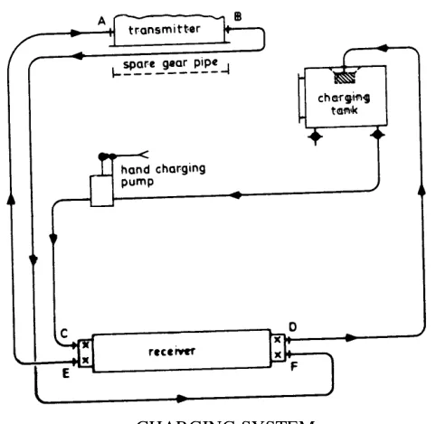
The connections for charging at the steering telemotor, A and B, are joined with a spare gear pipe, and the pipes at the charging valves, C and D, are disconnected. Clean oil is now added to the charging tank, and a head must be maintained here at all times.
Using the pump, oil is pumped until a clear discharge occurs at C. The pipe connection at C can now be replaced, open charging valves C and D and the circuit valves E and F. Continue pumping until the oil passes right through the circuit to discharge at D; when clear, close the pipe connection joint at D, remove the spare gear pipe and couple up the pipes to the steering telemotor.
The purpose of the washing-through is to flush out the old oil, dirt and water before the system is filled with clean oil. Doing it in sections, one at a time, is what makes it work: each section is flushed and then connected, so that dirty oil from one part is not pushed into a part already cleaned.
A constant head must at all times be maintained in the charging tank, otherwise air can be admitted to the system. A spring loaded valve is provided, normally in the return line to the charging tank, to prevent oil backflow from the highest point (the steering telemotor) when charging, and giving air entry and vacuum problems.
The spring loaded valve is there because the telemotor on the bridge is the highest point in the system. When charging stops, the oil in the pipe up to the bridge would drain back down, and the resulting vacuum would draw air in. The valve holds the oil in place.
The steering wheel is put to mid position, bypass valve open, charging shut-off valve open. Pump until the replenishing tank is full and all air is clear at the steering telemotor; close the shut-off valve and the air cocks.
Repeat the procedure for the receiver telemotor until all air is clear and oil returns to the charging tank. Close the charging valves, close the bypass valve, open the charging shut-off valve.
The gear is now ready for testing: (a) for leaks; (b) that movement at each receiver corresponds in direction and amount; (c) that there is definitely no air in the system.
Those three tests are worth noting as a model of how to finish a hydraulic job. A leak test, a correspondence test and an air test — the first proves the system is sealed, the second proves it is correctly connected, and the third proves it is full. All three are needed, and any one of them omitted leaves a fault that will appear at the worst moment.
8. Air in the system, and testing for tightness
Air in any hydraulic system must always be avoided, and the telemotor system is no exception.
Air being compressible gives incorrect balance between units, time lags and irregular operation, which can be dangerous.
Three distinct faults from one cause, and it is worth separating them:
- Incorrect balance between units — because air compresses, the receiver does not move by the same amount as the transmitter. The rudder angle ordered and the rudder angle achieved no longer correspond.
- Time lags — the air has to be compressed before the oil moves, so the rudder responds late.
- Irregular operation — the air moves about in the system, so the behaviour changes from movement to movement.
Its presence in the system is indicated by defective steering, jerky operation, and perhaps jumping at the pressure gauges.
The jumping pressure gauge is the classic symptom: a gauge needle that flickers rather than moving smoothly is reading a mixture of oil and air.
Air can usually be kept out with a tight system after proper charging, but should air get into the system it may be removed by purging at the air cocks. Should a large quantity of air gain access giving faulty steering, then probably the only course is to totally empty and recharge.
Water and dirt should also be avoided in the system.
Testing the telemotor for tightness
To test most gears for tightness, the wheel can be lashed over, first one side then the other, at a pressure of about 42 bar, which should hold for a considerable time.
The method is simple and effective: hold the system under pressure and see whether the pressure stays. The 42 bar is well above the normal working pressure of the telemotor, so it is a genuine test rather than a confirmation.
Leakage at either side means that all pipe joints and glands must be examined.
To test the bypass valve, the above procedure is repeated but with the liquid saving (or circuit) valves on the receiver telemotor shut. This loads each of the valves on the bypass unit in turn.
Shutting the circuit valves isolates the bypass unit, so the pressure test now applies to the bypass valve's own components. Same test, different subject.
9. The hunting gear
The hunting gear is the feedback. It is the device that makes the gear stop when the rudder has arrived.
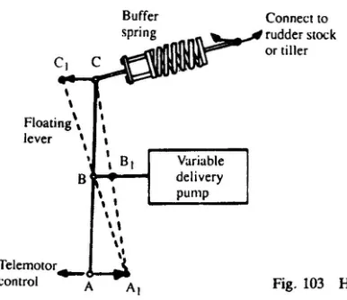
The pump control is moved by the telemotor through a floating lever. The other end of this lever is connected, through a safety spring link, to the rudder stock or tiller.
The telemotor is the receiver of the hydraulic remote control system from the wheel on the bridge. The linkage through the floating lever of telemotor, pump and rudder stock forms the hunting gear.
The pump is only required to deliver oil when the steering wheel is moved. The hunting gear returns the pump operating rod to mid position as soon as the helmsman stops turning the wheel. When the rudder has moved through the angle corresponding to the wheel position, it will remain there until the wheel and telemotor are moved again.
That paragraph is the heart of the whole control system, and it is worth restating in plain terms: the rudder angle is set by the wheel's position, and the gear stops when the rudder reaches it — because the rudder's own movement is what closes the pump's stroke off.
What happens when a sea hits the rudder
If the rudder is displaced by a heavy sea through lifting of the relief valves, the hunting gear is moved by the rudder stock. This will put the pump on stroke, and the rudder will be restored to its previous position.
This is a genuinely useful behaviour and it follows directly from the arrangement. Because the hunting point is connected to the rudder stock, the control system is not merely a remote control — it is a position controller. The rudder being knocked off its angle is, to the hunting gear, indistinguishable from the rudder not having got there yet. So the gear corrects it automatically, without the helmsman doing anything.
The safety spring link
The other end of the lever is connected through a safety spring link to the rudder stock.
The spring link is there so that the control mechanism does not have to be strong enough to take the rudder's shock loads. If the rudder is driven hard over by a sea, the spring link absorbs the movement rather than transmitting it as a destructive force into the delicate control gear. It also means that a jammed control cannot lock the rudder.
10. The floating lever
The hunting gear is built around a device called the floating lever, and it is the part of the system that people find hardest to picture. The manuals give three variants of it and a worked sequence, and the sequence is the way to understand it.
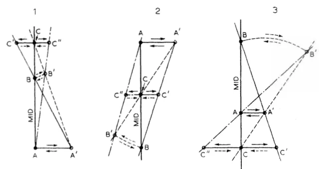
The three points
In each diagram the control movement is applied at point A, point B is linked to the body whose movement is to be controlled, and point C is linked to the control mechanism of the power source.
In a ship's steering gear:
| Point | Connected to | Moves when |
|---|---|---|
| A | The helmsman, through the telemotor | The wheel is turned |
| B — the hunting point | A point on the tiller | The rudder moves |
| C | The control lever on the pump | The lever geometry demands it |
The floating lever pivots alternately about points B and A, while executing the control and cut-off functions respectively, so that the lever floats in space. The distance between one or more pairs of attachment points on the lever varies as movement takes place.
In consequence, the motion of the lever is extremely complex and is difficult to visualize as a continuous process. However, if the geometry of the system is examined step by step at each of its rest positions, the principles of operation become clear.
That is good advice. The lever is not a rigid body pivoting about a fixed point; it is a lever whose pivot point changes, and whose attachment points slide along it. Trying to picture it moving continuously is hopeless. Looking at where it is at rest, before and after, works.
The design limitations
To make the geometry determinate and to ensure that it functions correctly, three limitations are imposed:
- Either point A or point C, but not both, should occupy a fixed location in the length of the lever; the other must be left free to move longitudinally in the lever, to accommodate the variation that occurs in the distance between them.
- Points A and C should be constrained to move on known loci, to ensure the accuracy of the system.
- Point B should be free to move longitudinally in the lever.
The first is the essential one. If both A and C were fixed in the lever, the geometry would over-constrain and the mechanism would jam as the rudder moved. One of them has to slide, and the choice of which one is what produces the three variants.
The worked sequence
This is the clearest description of the mechanism available, and it is worth following slowly.
Assume a ship to be proceeding on a straight course. Points A, B and C in each of the diagrams lie on the mid line, since the steering controls and the rudder are centralized and the pump is in the no-stroke or neutral condition.
Movement of point A to A′, which corresponds with the rudder angle required, causes the floating lever to pivot about point B, and point C moves to C′, placing the pump on-stroke in the correct sense.
So: the helmsman moves the control, the lever pivots about the hunting point (which is not moving yet, because the rudder has not moved yet), and the pump goes on stroke. The gear starts to move.
As the rudder moves over towards the angle ordered by the movement of A to A′, point B, which is linked to the tiller, moves towards B′, with the floating lever now pivoting about A′, being held there by the helmsman. This causes point C′ to return to C.
The helmsman has stopped moving the wheel, so point A is now stationary at A′. The lever's pivot has transferred to A′, and the rudder's movement is now driving the pump control back towards neutral.
Points B′ and C′ arrive at B and C simultaneously, placing the pumps in the no-stroke condition and bringing the rudder to rest at precisely the angle ordered.
That is the cut-off, and the phrase at precisely the angle ordered is what the whole geometry is for.
If now the control point is moved back from A′ to the mid position A, the floating lever pivots about B′, point C moves to a new position C″ on the opposite side of the mid line, placing the pump on-stroke to drive the steering gear back towards the mid position. The lever again pivots about A as the gear returns, point B′ moves back to B, causing C″ to move back to C, thus placing the pumps in the no-stroke condition and bringing the rudder to rest in the mid position.
The same sequence in reverse, and the result is a rudder that returns exactly to midships.
Movement of point A to a position A″ on the opposite side of the mid line, and then back to A, would have a similar effect, except that the rudder movements and all the hunting movements would also occur on the opposite side of the mid line.
Recognising one in the field
The mechanical arrangement of a floating lever system may not always be in one of the three forms illustrated, but if the principle is understood, and it is kept in mind that its basic functions are to initiate movement of the steering gear and to stop movement when the rudder arrives at the angle ordered by the helmsman, the reader should have no difficulty in recognizing any floating lever arrangement he may encounter.
That is the practical instruction, and it is the right one: look for the three points — where the control comes in, where the rudder feedback comes in, and where the pump is driven — and the rest follows.
11. Enclosed hunting gear and the control box
On a modern gear the control and hunting gear is not a set of levers out in the open. It is built into a self-contained unit.
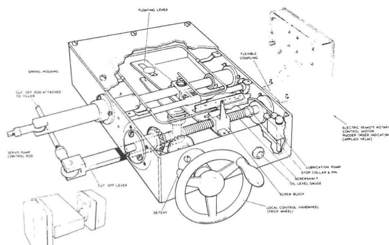
The light construction of the combined control and hunting gears is possible because the forces concerned are moderate. The self-contained unit is self-lubricating, and contained in an oil-tight case.
Steering gear pump output, and therefore rudder movement, is controlled by a floating lever, one end of which is moved by the control motor (or telemotor), the other end by the movement of the tiller. A rod attached to its mid-point and to the pump control lever puts the pump on stroke, in response to movement of the floating lever by the control motor or telemotor. As the tiller moves, the cut-off linkage acts to counteract the movement and brings the gear to rest by restoring the pump control lever to the no-stroke position.
Spring links, suitably disposed, obviate over-stressing of the mechanism.
The end of the floating lever connected to the remote control mechanism is attached to a block which moves along the screw shaft when the latter is rotated by the control motor or by the local control handwheel. Stroke is restricted by stop collars.
So the control box contains: a screw shaft turned either by the electric control motor or by hand, a block that travels along it, a floating lever, the spring links and the connection to the pump control. Everything in an oil-tight, self-lubricating case.
The local handwheel
The handwheel for local control has a bevel gear which engages with a similar wheel on the screwed shaft, when a catch (detent) is lifted and the handwheel is pushed in.
The screw shaft is normally turned to the required position by a split field electric motor.
The detent is the interlock, and it does the same job as the telemotor bypass valve's mechanical interlock: it prevents the local handwheel from being engaged accidentally. The handwheel sits there permanently, but it cannot drive anything until the detent is lifted and the wheel is pushed in. That is the difference between a handwheel that is a standby and a handwheel that is a hazard.
Normally the gear is controlled from the bridge through an electric telemotor and local control box, but a local control handwheel is also provided, as is a means of communication with the bridge.
The local control arrangements, and when they are used, are described in Chapter 8.
12. The electrical telemotor
Electrical control of the steering gear has become the norm, with the hydraulic telemotor, if installed at all, being used only in an emergency. This is the system that replaced it.
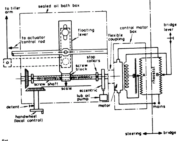
Bridge remote control is either electric, hydraulic or gyro pilot.
The system has been reduced in size and grouped into an oil bath box, in which the principle is almost identical but the input is electric in this case.
A bridge lever moves rheostat B, and unbalance current flows to rotate the control torque motor and hunt rheostat A back to equilibrium, when the motor will stop.
The mechanism is a small electrical analogue of the floating lever, and it is worth noticing the correspondence: two rheostats instead of two lever ends, a torque motor instead of a pump control, and electrical balance instead of geometric cut-off. The function is identical — move the demand, and the system drives until the demand and the feedback agree.
Electrical input is most common in modern practice, and motor drive via a flexible coupling (or electromagnetic clutch) rotates the screw shaft in the control box. This causes the screw block to move and, through the floating lever, causes movement of the actuator control rod.
This electrical-mechanical transducer also has limit switches and may utilise synchros and gear trains.
To change to local mechanical input control, the electrical control is switched off and the spring detent on the handwheel lifted, whilst the handwheel shaft is pushed home so that the spur gear engages when the detent is released to lock the shaft.
The electro-hydraulic telemotor
There is a third arrangement, which sits between the purely hydraulic and the purely electrical:
It utilises control signals from an auto-helmsman order synchro, amplified to operate solenoid valves controlling the direction of flow from a small oil pump to one side or the other of a ram connected to the actuator control rod, with feedback synchro.
The input is electrical, the transmission is a small hydraulic system, and the output is a mechanical movement of the control rod. It is the hydraulic telemotor with an electrical order instead of a wheel.
The control terminology
It is useful to consider control aspects. The deviation signal on the control rod is the result of a proportional movement of the screw block from the helm — the desired value — and the feedback signal from the tiller arm rod, acting on the floating lever.
That is the language of control engineering applied to a steering gear, and it is worth having. The screw block's position is the set point. The tiller rod is the measured value. The floating lever subtracts one from the other, and the difference is what drives the pump. A steering gear is a proportional controller with feedback, built out of levers.
13. The torque motor and servo valve control
The newest arrangement removes the mechanical linkage and the hunting gear from the steering gear altogether, and puts the control into the pump itself.
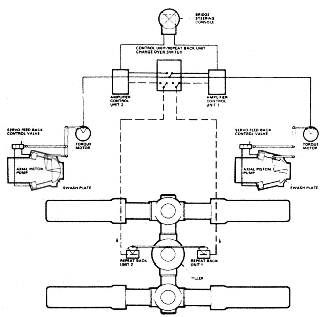
A torque motor, receiving the appropriate signal from the bridge through an amplifier unit, actuates the floating lever, putting the pumps on stroke in response.
The hunting action of the floating lever is no longer required, as the normal control of the steering gear from the bridge is by electric signal.
The signal is directed to the torque motor, which operates the servo valve that in turn controls the pump. When the steering gear has attained the required rudder angle, the electric feedback unit connected directly to the rudder stock cancels the input signal to the control amplifier, and the steering gear is held at that angle until another rudder movement is required.
This form of control eliminates the need for mechanical linkage and hunting gear on the steering gear.
The important sentence is the one about the electric feedback unit connected directly to the rudder stock. The feedback is still taken from the rudder itself, which is what makes the system a position controller rather than a speed controller — exactly as the hunting point on the tiller was. What has changed is only the means: an electrical signal from the stock instead of a mechanical link to the tiller.
The advantage is significant. There is no floating lever to wear and lose its geometry, no spring link to break, and no long linkage to go out of adjustment. The disadvantage is that the control now depends on an electrical signal and an amplifier, which is why the second independent control system required by the rules (Chapter 1) matters on this kind of installation.
The pump hardware that this system drives — the torque motor, the servo valve, the servo cylinders and the pump's own internal hunting action — is described in Chapter 5.
14. The Ward Leonard system
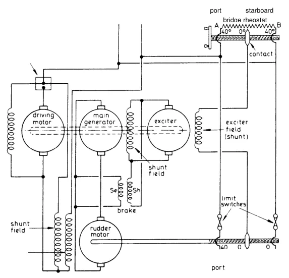
The Ward Leonard system is an all-electric steering gear, and it is worth understanding because it is a complete working example of a motor-generator control system, and because the principles it uses are the principles behind many other variable-speed drives.
The four electrical facts it depends on
- If a direct current generator is driven at constant speed and direction, then the magnitude and direction of the voltage is dependent on the magnitude and direction of the current through the field windings.
- The magnitude and direction of the armature current to a direct current motor having constant field excitation in one direction decides the magnitude and direction of the output torque.
- When a steady current flows in a uniform conductor there is a steady voltage drop along the length of the conductor.
- If a voltage is applied to the ends of two uniform conductors joined in parallel, then a current between zero and maximum can flow in either direction by connecting suitable points on the conductors.
Fact 1 is the control of the generator's output; fact 2 is how that output becomes torque; fact 3 is what makes a rheostat work as a position sensor; and fact 4 is the bridge circuit itself.
The bridge
The control gear employs two rheostats connected up as a Wheatstone bridge circuit, connected to the mains supply.
With the two contacts in the same positions — equal electrical voltage, that is, correspondence of rheostat position on the conductor or rheostat of bridge and rudder — then no current flows between them.
So the bridge rheostat is moved by the helmsman and the rudder rheostat is moved by the rudder. When the two agree, the bridge is balanced and no current flows. That is the electrical equivalent of the floating lever being at rest.
If the wheel is moved, say from amidships to starboard, the contact moves on the screw towards B and alters its position on the bridge rheostat. This means the two contacts are at different voltages (Fact 3). Current therefore flows between the contacts in a fixed direction. If the wheel had been moved to port, that is towards A, current would have flowed in the reverse direction, the magnitude of the current depending on the amount of movement of the steering wheel contact along its rheostat — which gives the necessary voltage difference between the contacts.
Thus a variable magnitude and direction current can be made to flow in the exciter shunt field (Fact 4).
That is the whole control signal: a current whose direction says which way to steer and whose magnitude says how far. One pair of wires carries the entire command.
The machine train
The main motor drives the main generator and exciter, the motor taking current from the mains supply.
With the contacts in equivalent positions, no current flows in the exciter field and no current is induced in its armature even though it is rotated. Similarly for the main generator: hence it produces no voltage and no current is supplied to the rudder motor armature.
The rudder motor is field excited from the ship's mains, but this will not produce torque without armature current, so the motor is stationary.
So with the bridge balanced, the whole train is running but nothing is happening: the exciter generates nothing, the main generator generates nothing, and the rudder motor has a field but no armature current. No current anywhere means no torque, and the rudder is held still. That is a genuinely elegant way to hold a rudder: nothing is locked, nothing is braked, there is simply no force being produced.
Steering to starboard
With the bridge contact moved to starboard, current flows in one direction through the exciter field, and the armature now produces volts, which sends a current through the generator field. A current now flows through the rudder motor armature, and the rudder motor rotates the rudder.
The hunting gear now functions so that the rudder movement moves the contact on the rudder rheostat to follow the bridge rheostat, that is, towards D. When the bridge wheel is stopped, the hunting gear brings the two contacts into equivalent voltage again, to cause no current to flow through the exciter and subsequent circuits, and so stop the rudder motor in the correct position.
The chain is: rheostat imbalance → exciter field current → exciter voltage → generator field current → generator voltage → rudder motor armature current → torque. Four stages of amplification, each one driven by the one before, and the whole chain stops the moment the bridge balances.
Steering to port
If the wheel is moved to port, current flows in the reverse direction, so that the generator produces reverse direction current (Fact 1). This current will produce opposite direction of rotation for the rudder motor (Fact 2), and the contact of the rudder rheostat is hunted towards C until equilibrium again exists.
Same chain, reversed. The direction of the whole train is set by the direction of one small current in the exciter's field.
The exciter as a current amplifier
The exciter is really a current amplifier, to reduce the current required at the rheostat contacts whilst giving sufficient current through the generator field.
This is the reason the exciter exists at all. The rheostat contacts on the bridge cannot carry the current the generator's field needs — they are small, delicate, and moved by hand. The exciter takes a tiny current at low power and uses it to control a much larger current. It is the electrical equivalent of the relay, and it is the reason the bridge rheostat can be a small instrument.
The rest of the machine
The series field of the rudder motor automatically gets a boost current when the driving motor comes on extra power with the generator and exciter producing current, and this boost serves to overcome the inertia of the rudder gear.
Limit switches are fitted on the contacts to cut off current at about 36° position, before the mechanical stops are reached.
The brake is kept on whilst no current flows in the rudder motor armature, and when current flows another resistance comes into parallel, so reducing the total resistance and allowing rotation of the rudder.
The brake functions to slip at a predetermined load, so producing current, and this boost serves to overcome the inertia of the movement, and is usually transmitted by a pinion, wheel and spur gear or by worm and wheel to a rudder quadrant.
Three details worth separating:
- The limit switches at about 36° are an electrical stop set just inside the mechanical stops. This is the same principle as the telemotor's 35° stops: stop the demand before the mechanism reaches its hard limit. It is worth noticing that the figure here is 36° rather than 35° — the electrical limit is a backstop, not the working limit.
- The brake is a fail-safe device. It is applied whenever there is no armature current, so a loss of control applies the brake. That is a real advantage over a hydraulic gear, which has no brake at all (Chapter 11).
- The transmission to the rudder quadrant is by gearing, not by a tiller and rams. An all-electric gear turns a rudder quadrant — a toothed arc on the rudder stock — rather than pushing a tiller.
Damping
To stop excessive hunting, a damping coil in the exciter circuit is provided, which is wound in opposition to the exciter field winding.
The damping coil is the electrical equivalent of the dashpot on an engine governor (see the auxiliary engine volume): it responds to rate of change, not to position. When the control is changing quickly the damping coil opposes it, and when everything has settled it has no effect. Without it, the system would overshoot and hunt, because a fast-acting amplifier with feedback and no damping is an oscillator.
15. The single motor electric gear
The single motor gear is a simpler all-electric arrangement, and it is worth describing because it shows how the same functions can be obtained with fewer machines.
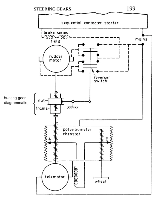
The armature of the telemotor is fed directly from the mains, and so is the potentiometer rheostat.
If B is moved, say down, by the wheel, then current flows due to the difference of potential between A and B. The telemotor field is now excited, and the telemotor rotates so as to bring A into line again and restore equilibrium.
So the telemotor here is itself a small electric motor whose job is to follow the wheel. It is the electrical version of the hydraulic receiver.
Through a screw nut, frame and fulcrum arrangement, the reverser switch is moved up and so closed.
Mains current then flows through the brake field (to release the brake), through the rudder motor series field and through the rudder motor armature.
The shunt field of the rudder motor (not shown) is permanently connected to the mains, but this is insufficient to cause rotation unless the series field is also excited.
That is the interlock that makes the arrangement safe. The rudder motor has two field windings: a shunt field that is always energised, and a series field that is only energised when the reverser switch closes. With only the shunt field, the motor produces no torque. So a failure that left the motor connected but the control dead would not cause the rudder to run away — the motor would simply sit there.
Rotation of the rudder motor is arranged to hunt back the rheostat contact A through a floating lever frame and screw nut arrangement, as well as opening the reverser switch.
If the reverser is moved in the other direction, the current direction is reversed through the rudder motor armature, but not through the field, so that rotational direction changes.
Reversing the armature current while leaving the field alone reverses the torque — the standard way to reverse a DC motor, and simpler than reversing both.
The single motor gear is, in effect, the Ward Leonard system with the motor-generator set removed and the rudder motor fed directly from the mains, with the control exercised by switching and reversing rather than by varying a generator's excitation.
16. Automatic steering
Automatic steering has been fitted since at least the 1950s, and it has changed the way ships are steered.
After the required course is set, the automatic steering maintains direction, correcting any deviations due to the weather. The automatic helm is consistent, with none of the fall off in performance that occurred in heavy weather with manual steering, when the human helmsman was changed.
That is the real advantage of the auto-pilot, and it is not the labour saved: it is that an auto-pilot does not get tired. A helmsman coming to the end of a four-hour watch in heavy weather steers less accurately than one just relieved, and the auto-pilot steers the same in the last hour as in the first.
Automatic steering has improved, and electrical control of the steering gear has now become the norm, with the hydraulic telemotor, if installed at all, being used only in an emergency.
Hydraulic telemotors, where fitted, should be regularly checked, however, with any leak being made good and the oil topped up.
That last point is worth emphasising, because it is where a standby system quietly stops being a standby. A hydraulic telemotor that is never used will not be maintained unless somebody deliberately maintains it, and a telemotor with a leak or a low oil level is not an emergency control — it is a false assurance. The routine checks in Chapter 9 cover it.
17. What the control system has to get right
Six things, and each of them is a way the control system can fail.
The order must arrive. A broken pipe, a broken wire, a seized linkage — the control path is long and it runs through places nobody looks at.
The order must be interpreted in the right sense. A control connected backwards steers the ship the wrong way, and the rudder angle indicator will show it (Chapter 2).
The gear must start smoothly. That is the variable delivery pump's contribution (Chapter 5), and it is what makes the rudder stop where it was told to.
The gear must stop at the angle ordered. That is the hunting gear's job, and it depends on the geometry of the floating lever being correct and unworn.
The rudder must be held at the angle ordered. Once the pump is at no-stroke, the gear is effectively hydraulically locked, and it stays put until the control moves again.
The system must be correctable by the person on watch. The auto-pilot must hand over to manual cleanly, and the hydraulic telemotor's bypass must be in the right state. That is the failure that caused a collision, and it is why the changeover procedure is displayed in two places and drilled every three months.
The one thing that makes all six work is the feedback. Take the hunting gear away — or leave it disconnected, or let it go out of adjustment — and the gear becomes an open-loop remote control that will drive the rudder hard over and keep it there. Every control system in this chapter, hydraulic or electrical, mechanical or electronic, has a feedback path from the rudder, and the feedback is the control system.