
Steering Gear Checks and Tests — Daily Rounds, the 12-Hour Test and Drills
What the engineer actually does with a steering gear — the routine checks, the pre-departure test, the drills, and the safe isolation procedure for working on it.
Key Principles at a Glance 6 points
- The daily and weekly checks are looking for change — a pressure that has drifted, a level that has fallen, a leak that has appeared — because none of those is a fault in itself, but each is the first sign of one.
- The monthly and six-monthly checks look after the things that decay slowly: filters load up and oil degrades, and neither shows on a daily round.
- The pre-departure test proves the automatic features — standby pump, automatic changeover, automatic restart, alarms and isolation — because they do nothing in normal service and are only worth having if they work.
- The three-monthly drill proves the manual features — local control, the after steering position, the communication and the alternative power — because a person has to operate them, and the drill is the only way to know that a person can.
- The dry-dock work measures the wear that cannot be measured at sea: rudder drop, bearing clearances and seals.
- The whole routine exists to answer one question in advance, while the answer is still useful: if the steering gear were needed in an emergency right now, would it work?
1. What is being operated
The routine is not a formality, and the pre-departure test is not a box to be ticked. A steering gear that has not been tested before departure has not been tested, and the ship sails with an assumption instead of a known state.
It helps to have the machine in mind before the procedures are described.
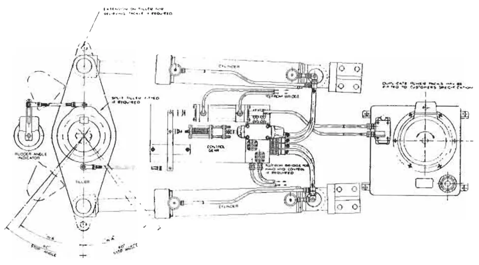
A steering gear compartment contains:
- The gear itself — the cylinders, rams, tiller and rudder stock.
- The carrier bearing — under the tiller, taking the rudder's weight.
- The power units — the electric motors, the couplings and the variable delivery pumps.
- The valve chest — the isolating, bypass, relief and hand pump valves.
- The oil — the replenishing tank, the storage tank and the pipework.
- The control gear — the control box, the telemotor receiver, the local handwheel and the trick wheel.
- The instrumentation — the rudder angle indicator transmitter, the pressure gauges, the tank level gauges and the alarms.
Everything in the routine check list is one of those, which is why the list can be remembered as a walk round the compartment.
2. The routine check list
The checks are grouped by interval. The intervals are the usual ones; the maker's manual and the ship's planned maintenance system override them.
Daily
Daily checks are the visual and sensory checks — the ones that find something going wrong before it has gone wrong.
- Inspect the sliding and moving parts for sufficient lubrication.
- Check for sufficient quantity of grease, and for the proper functioning of the greasing mechanism. Automatic greasing is fitted on present-day systems, operating when the steering gear is in operation.
- Inspect all connecting linkages.
- Inspect the pump seals and pipe connections for leakages.
- Check for sufficient oil level in the reservoirs.
- Check the temperature and pressure of the hydraulic oil for any deviation from normal values.
- Check the running hydraulic pump for correct functioning. Check the ammeter reading of the pump.
The pump ammeter is worth singling out. It is the one instrument that tells you how hard the pump is working, and a pump drawing more current than usual at the same rudder activity is a pump with a problem — a failing bearing, oil too cold, or a relief valve lifting when it should not.
Check the level of the following:
- The replenishing tank.
- The storage tank — this is the one that holds one complete system replenishment, required by the rules in Chapter 1.
Every week
- Check the various alarms and emergency changeovers.
- Check the communication from the bridge to the steering room. Repeat the procedure with the sound powered telephone.
The weekly check is short and it covers two things that fail silently. An alarm that has never been tested is not an alarm, and the bridge-to-steering-room communication is the link that makes every emergency procedure possible. The sound powered telephone is tested as well because it is the one that works when everything else has failed — it needs no power supply at all.
Every month
- Check and clean the hydraulic oil filters, or replace them as per the maker's recommendation.
Every three months
- Try out emergency steering from the local control station in the steering gear room, and log it in the log book.
Every six months
- Collect hydraulic oil samples and send them ashore for laboratory analysis.
Oil analysis is the only way to know the oil's condition rather than its appearance. Water content, viscosity, acidity and wear metals all change before the oil looks different.
Every dry dock
- As per the continuous survey of machinery, complete overhaul of the steering gear system, which includes the replacement of ram seals, the measurement of bearing weardown, and so on.
The dry-dock list is where the measurements in Chapter 2 and Chapter 10 are made: the rudder drop, the jumping clearance, the bearing clearances and the ram seal renewal. All of them need the ship out of the water or the rudder off its bearings, which is why they are dry-dock items and not running items.
3. Before departure — the test
Except in the case of ships regularly engaged on short voyages, the steering gear should be thoroughly checked and tested within 12 hours before departure. On short-voyage ships the test is carried out at least once a week.
The test procedure must include, where applicable, the operation of the following:
- The main steering gear.
- The auxiliary steering gear.
- The remote steering gear control systems.
- The steering positions located on the navigation bridge.
- The emergency power supply.
- The rudder angle indicators in relation to the actual position of the rudder.
- The remote steering gear control system power failure alarms.
- The steering gear power unit failure alarms.
- The automatic isolating arrangements and other automatic equipment as required for the steering gear.
The manufacturer's recommendations and the owner's instructions must be strictly followed.
The three things the test must include
The above checks and tests must include:
- the full movement of the rudder according to the required capacity of the steering gear;
- a visual inspection of the steering gear and its connecting linkage; and
- the operation of the means of communication between the navigating bridge and the steering gear compartment.
The three correspond to the three ways the gear can be wrong: it can be underpowered or restricted in travel (so full movement is checked); it can have a mechanical defect (so it is visually inspected); and it can be unsteerable in practice because nobody can talk to the people steering it (so the communication is checked).
The deck department should be informed, for ensuring that there are no obstructions in the way of the rudder. A rudder that is about to be put hard over with a mooring line or a boat rope over the stern is a rudder that is about to damage something. The warning is part of the procedure, not a courtesy.
4. Cold weather precautions
Cold weather is a steering gear problem in a way that is easy to overlook, because the oil in the steering compartment can be at ambient temperature.
In excessively cold ambient temperatures, the heating system in the steering gear compartment or any other oil heater, if provided, should be used.
At ambient temperatures below 10 °C, as the oil warms up, the gear should be moved slowly, in order to heat the complete hydraulic system.
The power units should be run for about 30 minutes prior to departure to raise the oil temperature, and occasional rudder movements made, to facilitate a uniform system temperature.
The oil level in the supply tank should be checked and topped up to about 75 per cent of its capacity.
Where arrangements are provided, the low level alarm should be tested.
Three things are being managed here and it is worth separating them:
- Viscosity. Cold oil is thick, and a pump drawing thick oil needs far more power and may cavitate. The pump's ammeter reading will be high, and the relief valves may lift. Warming the oil before departure is what prevents a gear that will not respond properly on a cold morning.
- Uniformity. Moving the gear slowly and making occasional rudder movements distributes the warmed oil through the whole system rather than just the pump. A system with hot oil in the pump and cold oil in the cylinders behaves unpredictably.
- Expansion and level. Cold oil occupies less volume than warm oil. Topping the tank to about 75 per cent — rather than right up to the mark — leaves room for the oil to expand as it warms without overflowing. The 75 per cent figure is the same one used for purging the system (Chapter 10).
The low level alarm test is included because cold oil contracting can bring the level down to the alarm point, and a low level alarm that has not been proved is not a protection.
5. What is checked on the gear itself
Beyond the nine items in the formal test, there are checks on the gear's mechanical state that the duty engineer makes.
The duty engineer should check that:
- The linkages are free for satisfactory operation.
- The sliding surfaces are duly lubricated.
- There are no leakages in the hydraulic oil.
- The rams ought to be lubricated with the system oil.
- The individual grease nipples, or the central greasing system if fitted for the ram guides, are verified for being full and for lubrication being provided.
The point about the rams being lubricated with the system oil is worth noting. The ram surface is a sliding seal surface; it is lubricated by the hydraulic oil itself, and it must not be lubricated with grease. Grease on a ram will be pushed into the cylinder and will damage the seal. The grease nipples are for the ram guides — the guide beams and slippers described in Chapter 3 — which are separate from the pressure seals.
The sliding surfaces that need lubrication are the ram guide surfaces, the tiller arm in its swivel block or the codpiece in its jaws, and the crosshead slippers. All of them are in Chapter 3, and all of them are dry metal-on-metal contact under load.
6. The test sequence
The formal test has a sequence, and the sequence matters because each step sets up the next.
The connecting pin should be removed from the "steering from navigating bridge position" and inserted into the position for control of the "steering by the trick wheel from within the steering gear compartment".
The rudder should be moved from hard-over to hard-over, using each power unit in turn, before cutting off the power to test the audible and visual alarms on the bridge.
So the first phase tests: the trick wheel works, each power unit works, the full travel is available, and the alarms work. Simultaneously, the position of the tiller as indicated in the steering gear compartment should be verified against the position indicated on the bridge by the rudder angle indicator, utilising the communication system provided. The rudder angle indicator is being checked against the actual rudder, which is the only way to prove it is telling the truth.
The indicating light provided on the bridge to demonstrate the running motor of the power unit in service should be verified for satisfactory operation.
The connecting pin is restored in position for telemotor steering, and then the tiller should be operated from the bridge, using the port power unit to start with.
Now, disconnecting the power supply to this port unit would test the effectiveness of the automatic startup arrangements, if provided, by bringing into service the starboard unit, which could otherwise be started manually from the bridge.
This test may be repeated by starting with the starboard motor.
That is the test of the standby unit's automatic changeover, and it is the one test that cannot be done any other way. Disconnecting the running unit's supply is the only way to find out whether the standby starts itself, and a standby that does not start itself is not a standby.
With both the power units running, opening the power supply breaker and then closing it would check the automatic restart arrangements.
Each control system provided ought to be tested.
The level of the hydraulic fluid in the tank (reservoir) should be checked.
The whole sequence, summarised:
| Phase | What is proved |
|---|---|
| Pin to trick wheel, both units, hard over to hard over | Local control, both power units, full travel, alarms |
| Tiller position compared with bridge indicator | Rudder angle indicator is truthful |
| Running motor indicating light | Bridge indication of which unit is running |
| Pin back to telemotor, steer from bridge | Bridge control restored |
| Cut the running unit's power | Automatic changeover to standby |
| Open and close the breaker with both running | Automatic restart on power restoration |
| Each control system in turn | No single control failure removes steerage |
| Tank level | No loss of oil |
The pattern is that every automatic feature is proved by provoking it. The standby is not checked by looking at it; it is checked by taking the running unit away and seeing whether the standby comes on.
7. At sea
The steering gear is tested before departure, and then it is watched.
While the ship is at sea with the automatic pilot in prolonged use, manual steering must be tested before entering busy or restricted waters. When in such waters, both power units — pumps and motors — must be running if simultaneous operation is possible.
That instruction is one of the most important in the whole routine, and the reason is the one given in Chapter 7: the auto-pilot is a control system, and a control system that has been in use for days has not been proved to hand over cleanly. The test before entering restricted water is what prevents the handover failing at the moment it is needed.
When special cautions are required to be exercised during navigation, ships must have more than one steering gear power unit in operation when such units are capable of simultaneous operation.
Running both units in restricted water is not about redundancy; it is about response. Two pumps deliver twice the oil flow and put the rudder over in half the time, which is what is wanted in a channel.
8. The three-monthly drill
Emergency steering drills must be conducted at least once every three months. The drill must include:
- direct control of the system within the steering gear compartment;
- the feasibility of communications with the navigation bridge; and
- the operation of alternative power supplies, as applicable.
This will enable the practising of emergency steering procedures.
Every three months an emergency steering drill should be held, and should include direct control from within the steering compartment, at which time the use of the communications procedure with the navigating bridge should be practised.
The drill is not a demonstration to a surveyor; it is the only occasion on which the emergency arrangements are exercised. The three elements correspond to the three things that go wrong in an emergency:
- The local control does not work — a seized handwheel, a missing pin, a linkage nobody has moved in three months.
- The communication does not work — and then the person in the flat and the person on the bridge cannot tell each other what they are doing, which is how a rudder gets put over the wrong way.
- The alternative power does not come on — a flat emergency battery, a breaker left open, a changeover switch nobody has operated.
All officers are required to be familiar with the steering gear and the changeover arrangements. The drill is how that familiarity is maintained, and the log entry is how it is demonstrated.
9. Non-mandatory equipment and waivers
Two provisions cover the edges of the requirement.
In case certain ships are provided with equipment in excess of that which is mandatory, all testing and drill stipulations are to be made equally applicable to the non-mandatory equipment.
This is a sensible and easily forgotten rule. If a ship has a second control system that the rules did not require, that second system must be tested to the same standard as the first. Otherwise the ship has an untested extra that everybody assumes is a backup.
Waivers may be given by the Administration from the checks and tests marked above, to ships which regularly engage on voyages of short duration. In such cases the checks and tests are to be carried out at least once a week.
A ferry doing six crossings a day cannot test its steering gear before every departure. The waiver acknowledges that, and substitutes a weekly test. What it does not do is remove the requirement — the tests still have to be done, just less often.
10. Records, familiarity and instructions
The rule is in Chapter 1: the instructions for changeover must be displayed in the steering compartment and on the bridge, and the officers concerned must be familiar with the systems fitted and the changeover procedures. What follows is what that means in practice.
Masters and Chief Engineers are required to ensure that all equipment is checked and tested, and also that their respective officers concerned with the operation or maintenance of steering gears are familiar with the operation of the steering systems as fitted on board, along with the procedures for changing from one system to the other.
The various tests and checks should be logged.
The instruction to display the changeover procedure in both places is worth thinking about. In an emergency, the person who has to make the changeover may be the officer of the watch on the bridge or the engineer in the flat, and neither will have time to fetch a manual. The card on the bulkhead is the whole of the training in that moment.
The log entry is what turns a check into a record. A test that has been done and not recorded cannot be proved to have been done, and it cannot be compared with last month's result — and the comparison is what tells you the gear is deteriorating rather than merely working.
11. Safe isolation of the system
Before any work is done on the gear — opening the valve chest, renewing a seal, working on a pump — the system must be isolated. The procedure is specific and every step has a reason.
- Remove the auto standby pump from the auto position.
- Stop the electric motor of the hydraulic pump.
- Put the control room circuit breaker off.
- Obtain the electrical isolation permit, and put the local electrical panel circuit breaker off.
- Shut off the relevant isolating valves on the piping circuit between the pumps and the actuators, the storage tank and the replenishing tank.
- Inform the bridge.
- Display the "men at work" warning board.
Reading the steps in order, they fall into three groups:
Take the automation out first. Step 1 is the one that would be forgotten. An automatically started standby pump can start at any moment, and it does not care that somebody has their hands inside the valve chest. Taking it out of auto is the first thing done, before anything else.
Isolate the electricity, and prove it. Steps 2 to 4 take the motor off, then the breaker off, then the permit obtained. The permit is the formal record that the circuit is isolated and that nobody is going to close the breaker while work is in progress.
Isolate the hydraulics, and tell everyone. Steps 5 to 7 shut the oil off, tell the bridge that the gear is out of service, and put a board on it. Informing the bridge is essential: the bridge must know that moving the wheel will do nothing, or worse, that moving the wheel could injure somebody.
The procedure is also described in Chapter 12 as a safety matter, because that is what it is.
12. Filters and cleaning
Usually filter cleaning is carried out if the differential pressure drop across the filter is high, or in some cases the visual indicator located on the filter is in the "red level".
That is the condition-based instruction, and it is better than a fixed interval: the filter is cleaned when it needs cleaning, not when the calendar says so.
There are two different types of filters:
- The inlet side of the pump is provided with a filter capable of removing chips, with a filtration level of 50 microns.
- Silt filters are positioned in the return line. They are also called return line filters.
The two filters do different jobs and it is worth keeping them apart:
The pump inlet filter protects the pump from chips — solid particles, swarf, the debris of a failing component. 50 microns is a coarse-ish figure by hydraulic standards, deliberately: a fine filter on the suction side of a pump would restrict the flow and cause cavitation. The inlet filter's job is to stop big pieces, not to polish the oil.
The return line silt filter catches the silt — the fine wear products and degradation products that accumulate in the oil as the system works. It is on the return line because that is where the oil is at low pressure and a fine filter can be used without restricting anything.
There is also a 10 micron filter F10 in the auxiliary pump discharge on the two-ram circuit described in Chapter 4, protecting the servo-controls and the change-over valves. So a typical installation has three filters at three different places, each matched to what it is protecting.
13. What the routine is really for
Reading the check list and the test procedure as a whole, the purpose is clear enough.
The daily and weekly checks are looking for change. A pressure that has drifted, a level that has fallen, a leak that has appeared, an ammeter reading that is not what it was. None of these is a fault in itself; each is the first sign of one.
The monthly and six-monthly checks are looking after the things that decay slowly. Filters load up and oil degrades, and neither shows on a daily round.
The pre-departure test is proving the automatic features. The standby pump, the automatic changeover, the automatic restart, the alarms and the isolation arrangements are all things that do nothing in normal service and are only worth having if they work. The test is the only way to know.
The three-monthly drill is proving the manual features. The local control, the after steering position, the communication and the alternative power are all things a person has to operate, and the drill is the only way to know that a person can.
And the dry-dock work is measuring the wear that cannot be measured at sea. The rudder drop, the bearing clearances and the seals are all in Chapter 10.
Put together, the routine exists to answer one question: if the steering gear were needed in an emergency right now, would it work? Everything in this chapter is a way of asking that question in advance, while the answer is still useful.