
Air Conditioning
Same plant, different objective — the target is human comfort, so humidity matters as much as temperature.
Key Principles at a Glance 8 points
- Air conditioning is the control of humidity, temperature, cleanliness and air motion — not simply heating and cooling.
- Heating cold outside air to 21 °C greatly increases its capacity to take up moisture, drying the nasal passages, mouth and throat unless it is humidified.
- Cooling alone brings air to 100 % relative humidity, at which point perspiration cannot evaporate to cool the skin — which is why over-cooling and reheat is used.
- The comfort target is about 21 °C and 50 % relative humidity, with a minimum of 40 % relative humidity at 21 °C to limit condensation on external bulkheads.
- About 25 to 30 % of the air is drawn from outside; the balance is recirculated to save heating cost.
- Drainage is the Legionella control measure — anywhere water can stand in the unit is a potential breeding site, which is why steam humidifiers are preferred over water spray types.
- The dirty air filter is by far the most frequent cause of air-conditioning malfunction, and a 15 % air flow loss costs about 9 % extra power.
- The psychrometric chart gives a quick performance check across the cooling coil: dew point, temperature, humidity and enthalpy.
1. What the Engineer Must Understand
The maker's manual and the SMS override. The M Notice on Legionella bacteria sets the cleaning and sterilisation intervals — these are not optional.
Air conditioning is the control of humidity, temperature, cleanliness and air motion.
- Winter conditioning relates to increasing temperature and humidity.
- Summer conditioning relates to decreasing temperature and humidity.
- Basically the practical difference is dependent upon whether the air fluid is passed over a hot grid (steam) or a cold grid (brine or direct expansion refrigerant). Water can be used instead of brine.
Why it is not just heating
Straight heating of air from the outside when the ambient temperature is very low, to attain an inside comfortable level of about 21 °C, greatly increases the capacity of that air to take up moisture from any available source. The hot air tends to dry the nasal passages, mouth and throat and cause discomfort, unless a means to humidify it is provided.
Why it is not just cooling either
Cooling brings the air to the dew point so that moisture is precipitated, and it will continue to condense out as the temperature is further dropped. At the end of the air's passage through the cooler it will have lost moisture (been de-humidified) but be left with the maximum moisture it could carry at the new low temperature: its relative humidity would be 100 %. Such air would be unable to absorb further moisture. Perspiration, instead of evaporating to cool the skin, would remain as unpleasant wetness, while the heat would make people perspire more.
The answer to that problem is over-cooling and reheat.
2. The Psychrometry the Oral Expects
2.1 Specific humidity
Is the ratio of the mass of water vapour to the mass of dry air in a given volume of mixture.
2.2 Per cent relative humidity
Is the mass of water vapour per m³ of air compared to the mass of water vapour per m³ of saturated air at the same temperature. This also equals the ratio of the partial pressure of the actual air compared to the partial pressure of the air if it were saturated at the same temperature:
where g refers to the saturation condition. This means dry air contains maximum moisture content (100 % R.H.) at the saturation condition.
2.3 Dew point
When a mixture of dry air and water vapour has a saturation temperature corresponding to the partial pressure of the water vapour, it is said to be saturated. Any further reduction of temperature (at constant pressure) will result in some vapour condensing. This temperature is called the dew point. Air at dew point contains all the moisture it can hold at that temperature; as the amount of water vapour varies in air then the partial pressure varies, so the dew point varies.
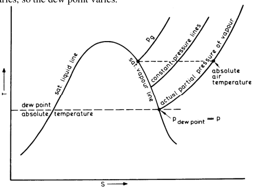
From the figure: cooling at constant pressure brings the low-pressure superheated vapour to the dew point, after which condensation occurs. Cooling at constant temperature increases the partial pressure until the saturation point is reached, thus relative humidity can be found.
2.4 Dalton's law of partial pressures
Dalton's law (as stated in the source): the pressure exerted by, and the quantity of, the vapour required to saturate a given space (i.e. exist as saturated steam) at any given temperature, are the same whether that space is filled by a gas or is a vacuum.
The general statement of Dalton's law: the pressure exerted by a mixture of a gas and a vapour, of two vapours, or of two gases, or a number of same, is the sum of the pressure which each would exert if it occupied the same space alone, assuming no interaction of constituents.
2.5 Dry bulb and wet bulb temperatures
The hygrometer (or psychrometer) consists of an ordinary thermometer which gives the dry bulb temperature, and a wet bulb thermometer (wetted gauze cover).
- The wet bulb reading will be less than the dry bulb reading; the difference is quoted as the wet bulb depression.
- The drier the air, the more rapid the moisture evaporation from the gauze, giving a cooling effect. Thus the greater the difference between the readings, the drier the air and the less the % R.H.
- Still-air thermometers are inaccurate, and hand sling types to secure air motion across the wick until equilibrium conditions exist are preferred.
2.6 The psychrometric chart
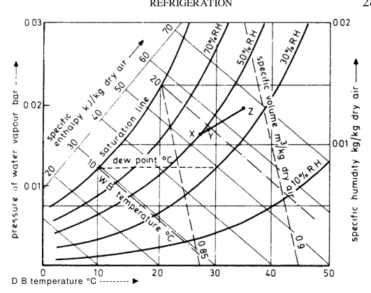
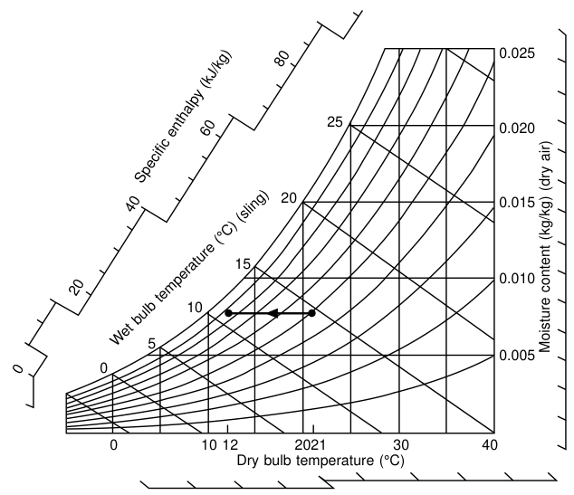
Cooling air at constant pressure gives constant moisture content, increasing in relative humidity until the saturation (dew) point is reached.
- Cooling air in practice gives some pressure drop due to fluid friction, but this is not high in a correctly designed plant. If the cooling rate is kept in line with the pressure drop then the relative humidity will stay constant; if the cooling rate is slower the relative humidity will reduce; if the cooling rate is faster (as it will usually be in practice) then the relative humidity will increase.
- The chart is drawn for a pressure of 1 bar but is sensibly accurate between 0.9 and 1.1 bar.
- From wet and dry bulb readings the various properties of the air–vapour mixture can be estimated. Enthalpy is a function of the wet bulb temperature, and moisture content and vapour pressure are functions of dew point.
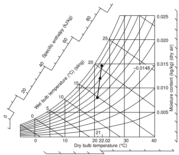
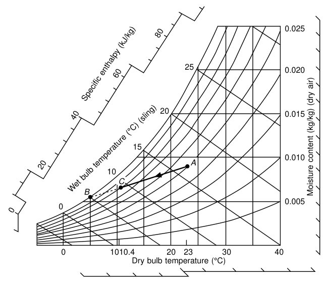
- The chart gives a quick performance check on the air entering and leaving the cooling coil — dew point, temperature, humidity, enthalpy, etc.
Mixing two airstreams — the worked method:
When dealing with air mixtures, for example 17 m³ of air at 35 °C D.B. and R.H. 40 % mixed with 83 m³ of air at 27 °C D.B. and R.H. 50 %, set off on the chart and proportion XZ off so that XY / XZ = mass of 17 m³ / mass of 83 m³, the masses being found from specific volumes (ignoring small water mass). Then Y is the condition of 100 m³ of mixture. In the example the result is 100 m³ at 28 °C D.B., R.H. 48 %.
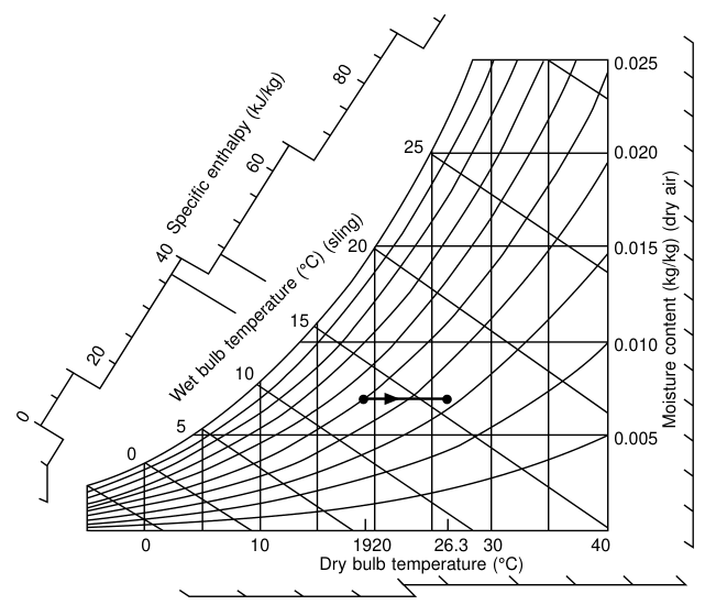
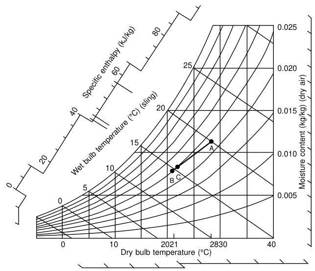
2.7 Air treatment cycles from the chart
These are the standard chart constructions an examiner may ask you to describe:
| Figure | Process |
|---|---|
| Sensible heating of air | Air heated at constant moisture content; dry bulb rises, R.H. falls |
| Mixing of two airstreams | Two states joined by a straight line; the mixture state divides the line in proportion to the masses |
| Sensible cooling of air | Air cooled at constant moisture content until the dew point is reached |
| Adiabatic saturation to ultimate condition | Air passed through a spray; approaches saturation along a constant wet-bulb line |
| The proportion | Graphical solution to the mixture proportion |
| Addition of steam to air | Steam injected; moisture content and dry bulb both rise |
| Air washer with chilled water | Air washed and cooled; both sensible and latent heat removed |
| Chilled water spray | Spray chamber with chilled water |
3. Comfort Conditions
3.1 The numbers
Comfort under summer conditions is dependent on dry and wet bulb readings and relative humidity as well as air motion. For a given degree of air turbulence (75 mm/s to 127 mm/s), relative humidity between 30 % and 70 %, average 50 %, and thermometer readings 19 °C to 25 °C, average 22 °C, gives the best degree of summer comfort.
Air at low temperature and high humidity can be as comfortable as air at high temperature and low humidity.
McGeorge's version, for the ship: in general, whether the air conditioning system is used for heating or cooling, a temperature of about 21 °C and relative humidity of 50 % is comfortable. Humidity is set lower in very cold conditions; temperature higher in very hot weather.
For comfortable conditions there should not be less than 40 % relative humidity when the accommodation is at 21 °C. Limiting humidity to no more than the minimum 40 % in very cold conditions will reduce condensation on inside surfaces of the external bulkheads.
3.2 Design differentials
- A differential of about 7 °C between inside and outside conditions is usually aimed at, but this is variable with the outside conditions, as a coil can extract large amounts of heat from warm dry air, so reducing temperature appreciably, or large amounts of moisture from humid air with little temperature reduction.
- The average temperature differential is about 11 °C between fan discharge and room temperature.
3.3 Air quantity and motion
- The amount of air recirculated depends on the installation, space conditions (smoking, etc.), degree of air motion (draughts, etc.), and so the number of air changes per day is a balance of quantity and temperature. Thus temperature, humidity and air motion are interrelated and the designer must correlate correctly.
- About 0.1 m³/m² floor space (accommodation) to 1.33 m³/m² floor space (kitchens) may be regarded as typical maximums, air motion about 100 mm/s.
- About 25 to 30 % of the air is drawn from the outside; the balance is recirculated. This saves heating cost but still provides a freshening supply and makes up for losses.
4. The Air Conditioning Circuit
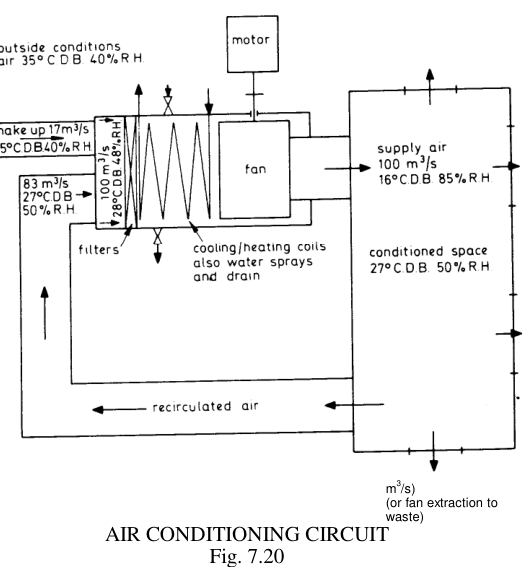
This figure is worth being able to reproduce from memory, because it contains the whole system in one diagram: make-up and recirculation, filters, cooling/heating coils with water sprays and drain, fan, supply to the space, leakage air, and recirculation.
The unit arrangement:
- The air conditioning unit (compressor, evaporator, condenser, etc.) will usually be independent from the rest of the refrigerating plant, although located often in the same space.
- The brine supply will be distributed to the cooling grids incorporated in a unit.
- The number of units would depend on the number of accommodation circuits necessary — say at least one unit per accommodation deck.
- Size of the plant would depend on the type of vessel.
- Leakage air must be cut to a minimum by closure of ports and doors.
- Air circulation would be through the normal louvre system to the various spaces. When heating is required the air would bypass the shut-down cooling grid and be passed over heating elements; in this case a controlled water spray controls humidity before leaving the unit.
- The temperature and humidity are controlled at the grid, drainage condensation being led away from the unit.
- Air motion will be determined by the initial design of the fans, ducts and louvres. The flow is usually by centrifugal or propeller type fans, and the humidistat or thermostat controller is situated at the unit together with fan controls.
5. System Types
5.1 Single duct, simple air conditioning
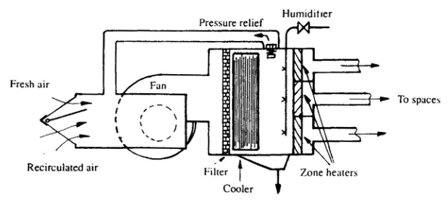
The single duct air conditioning unit can provide both heating and cooling with control of humidity. When neither heating nor cooling are required the plant is operated as a ventilating system only.
- Heating for the air is provided by steam heating coils, one for each space. Each is controlled by a thermostat set to give a temperature in the space of about 21 °C.
- Individual section thermostats are necessary to maintain even temperature in different areas which are affected by other factors — accommodation space near the engine room needs less heating than that in the upper part of the ship, for example.
- When the outside temperature is cold but not excessively so, the steam heater alone is used to maintain accommodation conditions. If outside temperature is very low then heat loss from the spaces will be high, and both the recirculating and fresh air will tend to have a drying effect due to the considerable heating. Extra moisture added to the air by the humidifier reduces its drying effect.
- The valve controlling steam for the humidifier may be hand-operated. It must be closed when the air is not being heated or when the fan is stopped.
- Cooling in the simple unit is by a freon direct expansion plant. The mixture of fresh and recirculated air is delivered via the evaporator, where it is cooled, to the spaces served by the fan. Local temperature is adjusted by volume control at the delivery point.
- Nylon filters are provided to keep the air clean (removed for washing every six weeks), and the drain clears excess water from humidification or de-humidification.
- Extraction fans discharge air from spaces such as the galley and toilets to the outside. This reduces air pressure in these areas so that tainted air will not flow from them to other spaces, but any flow will be in the other direction.
5.2 Over-cool and reheat — the principle worth explaining
The problem can be overcome by over-cooling the air in the cooler, so de-humidifying it to a greater extent (i.e. removing more water), and then reheating slightly to bring the temperature to the comfort level. Reheating increases the capacity of the air for carrying moisture and therefore drops its relative humidity. Final temperature is 21 °C (higher if outside air is very hot) and relative humidity about 50 %, for comfort.
This is the same trick the local reheat and twin duct systems use mechanically. It is the answer to "why not just cool the air to the required temperature?" — because you would arrive at 100 % relative humidity.
5.3 Twin duct system
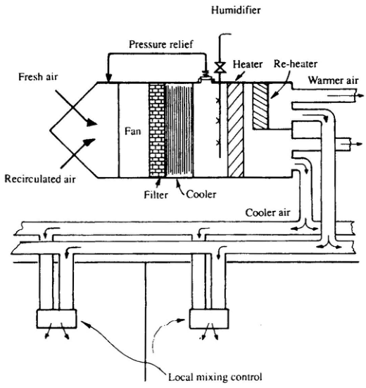
This gives the greater flexibility of temperature and ventilation required in a large passenger vessel.
- One set of ducting carries warm air, the other set carries a cooler supply from a central air conditioning unit to the accommodation spaces.
- The cold/warm air ratio is controlled within a particular cabin or compartment by a local mixing unit.
- Two temperatures are produced in the air conditioning plant by using the reheater on a proportion of the air supplied.
5.4 Local reheat system
Another variation uses an air conditioning unit with single duct type distribution and local reheating at the outlet in the space served. Individual temperature requirements are met by an electric element or hot water heat exchanger controlled by a locally set thermostat.
5.5 Other heating and cooling media
Heating of the air may be by steam (as above), hot water circulation, or electric heating elements. Cooling by chilled water or brine may be used instead of direct expansion. A humidistat can be installed for automatic humidity measurement and control.
6. Air Conditioning Plant in the Engine Room
- The air conditioning plant is usually independent of the cargo refrigeration plant, though often in the same space.
- Compressor duty: single-stage centrifugal compressors are common for air-conditioning duty, with rotor speeds usually about 10 000 rev/min.
- Condenser pressure control is critical because the lower the condensing temperature, the better the COP. A 350 kW air-conditioning plant goes from COP 3.41 at 35 °C to 4.73 at 25 °C.
- Air filters are the number one maintenance item.
7. Legionella Bacteria — The Safety Obligation
Legionella bacteria is a type of pneumonia which may be fatal to older people, and its presence has been associated with the air conditioning plant of large buildings. The outbreak which led to investigation occurred at a convention for American ex-servicemen (the American Legion), and the identified cause of the problem was therefore labelled legionella bacteria.
There is a risk that the bacteria could flourish in the air conditioning systems of ships and consequently a Department of Transport M Notice has been issued to give warning and to recommend preventative measures.
The M Notice explains that the organisms breed in stagnant water or in wet deposits of slime/sludge.
Possible locations for bacteria colonies are mentioned as being at:
- the air inlet area and below the cooler (stagnant water),
- in the filter,
- in humidifiers of the water spray type,
- in exposed insulation.
Recommended preventative measures:
| Measure | Detail |
|---|---|
| Drainage | Provision of adequate drainage is recommended to remove stagnant water. |
| Filters | Guidance is given for weekly inspection and cleaning as necessary of filters with a 50 p.p.m. super-chlorinated solution. |
| Cooler drain area | The solution should be used on the cooler drain area at not more than three-month intervals. |
| Humidifiers | Regular sterilization is called for with water spray type humidifiers (steam humidifiers being preferred). |
Reference: Merchant Shipping Notice no. M1215 (1986), Contamination of Ships' Air Conditioning Systems by Legionella Bacteria.
Drainage is the control measure. Anywhere water can stand in the air conditioning unit is a potential breeding site. Steam humidifiers are preferred over water spray humidifiers precisely because they leave no standing water.
8. Air Conditioning — The Practical Checks
| Check | Frequency | Why |
|---|---|---|
| Air filters | Weekly inspection; replace/clean as indicated by the manometer | By far the most frequent cause of malfunction; a 15 % air flow loss costs about 9 % extra power |
| Cooling coil, water side | As indicated by working conditions | Scale/algae fouling raises condensing/evaporating temperature differences |
| Condensate drain and tray | Regular | Stagnant water — Legionella breeding site; also prevents water carry-over |
| Humidifier | Regular sterilisation (water spray type) | Legionella |
| Cooler drain area | Super-chlorinated solution at not more than 3-month intervals | Legionella |
| Wet and dry bulb readings | With the running log | Gives relative humidity from the psychrometric chart; the only way to know the system is actually delivering comfort |
| Fan belt tension | Routine | May be missed if equipment is out of sight |
| Insulation | Periodic inspection | Exposed insulation is a Legionella location |