
Expansion Valves and Liquid Level Control
The device most often blamed and most often mis-adjusted on a ship — every type in use, and the diagnostic logic for each.
Key Principles at a Glance 5 points
- The expansion valve does three jobs: reduce the pressure, keep the evaporator active by modulating flow to the load, and prevent liquid flooding back to the compressor.
- Flash gas is not a fault — 25 to 35 % of the liquid boils off in the valve and cools the remainder below evaporator temperature, which is why a −18 °C evaporator can be fed from a −24 °C refrigerant.
- The TEV spring is set during manufacture and should not be adjusted; it provides the balance of p_s − p_e at the diaphragm and so sets the superheat.
- The superheat is normally set between 3 and 7 °C, typically about 5 °C — enough to guarantee no liquid reaches the compressor, but not so much that evaporator surface is wasted.
- An equalising connection must be provided when the pressure drop across the evaporator exceeds 3 bar; the TEV is an undamped proportional control and hunts continuously by design.
1. What the Engineer Must Understand
The maker's manual and the SMS override. The spring of a thermostatic expansion valve is set during manufacture and should not be adjusted unless the maker's procedure authorises it and the adjustment is recorded.
The purpose of the expansion valve is to control the flow of refrigerant from the high-pressure condensing side of the system into the low-pressure evaporator. In most cases the pressure reduction is achieved through a variable flow orifice, either modulating or two-position.
The three functions, in the shipboard wording:
McGeorge's phrasing, which is the one to quote: the expansion valve throttles the liquid refrigerant and maintains the pressure difference between the condenser and evaporator, while supplying refrigerant to the evaporator at the correct rate. It is thermostatically controlled.
The physical reason it works:
The liquid refrigerant leaves the condenser with a temperature just above that of the sea water inlet, say 15 °C. As it passes through the expansion valve the evaporating temperature decreases to −24 °C and some of the liquid boils off, taking its latent heat from the remainder of the liquid and reducing its temperature to below that of the evaporator.
The result: the refrigerant can be boiled off by an evaporator temperature of −18 °C, because the pressure drop brings the evaporating temperature of the refrigerant to say −24 °C.
Flash gas percentage: the flash gas amount varies between 25 and 35 %, depending on refrigerant type, plant capacity and ambient temperature.
2. Classification by Method of Control
Welch classifies expansion valves according to the method of control:
| Class | Type | Used on |
|---|---|---|
| Level | Low-pressure float valve | Flooded evaporators |
| Level | Low-pressure float switch + solenoid | Flooded evaporators |
| Level | High-pressure float valve | Single-evaporator flooded systems |
| Level | Thermostatic level control | Flooded evaporators |
| Superheat | Thermostatic expansion valve (TEV) | Dry expansion circuits |
| Pressure | Pressure control (constant pressure) valve | Fixed evaporator coil pressure |
| Superheat | Electronic expansion valve | Modern integrated control |
Plus, for small hermetically sealed units, the capillary tube (a fixed restriction, not a valve).
3. Hand-Operated Expansion Valve
Hand-operated expansion valves have the disadvantage that they require fairly regular manual adjustments.
A hand regulator is fitted for emergency use. It would be adjusted to give a compressor discharge pressure such that the equivalent condensing temperature shown on the gauge at the compressor outlet was about 7 °C above the sea water inlet, and the suction gauge showed an equivalent evaporating temperature about the same amount below the evaporator.
This is the shipboard fallback — if the TEV fails at sea, the hand regulator keeps the plant running until the valve can be renewed.
4. Float Valves
4.1 Low-pressure float valve
Flooded evaporators require a constant liquid level so that the tubes remain wetted. A simple float valve suffices, but must be located with the float outside the evaporator shell, since the surface of the boiling liquid is agitated and the constant movement would cause excessive wear in the mechanism. The float is therefore contained within a separate chamber, coupled with balance lines to the shell.
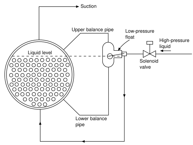
Such a valve is a metering device and may not provide positive shut-off when the compressor is stopped. Under these circumstances refrigerant will continue to leak into the evaporator until pressures have equalised, and the liquid level might rise too close to the suction outlet. To provide this shut-off, a solenoid valve is needed in the liquid line.
4.2 Low-pressure float switch
Since the low-pressure float needs a solenoid valve for tight closure, this valve can be used as an on–off control in conjunction with a pre-set orifice and controlled by a float switch.
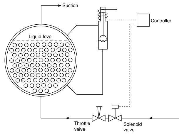
- The commonest form of level detector is a metallic float carrying an iron core which rises and falls within a sealing sleeve. An induction coil surrounds the sleeve and is used to detect the position of the core. The resulting signal is amplified to switch the solenoid valve, and can be adjusted for level and sensitivity.
- A throttle valve is fitted to provide the pressure-reducing device.
- Should a float control fail, the level in the shell may rise and liquid pass into the compressor suction. To warn of this, a second float switch is usually fitted at a higher level, to operate an alarm and cut-out.
- Where a flooded coil is located in a liquid tank, the refrigerant level will be within the tank, making it difficult to position the level control. In such cases a gas trap or siphon can be formed in the lower balance pipe to give an indirect level in the float chamber. Siphons or traps can also be arranged to contain a non-volatile fluid such as oil, so that the balance pipes remain free from frost.
4.3 High-pressure float valve
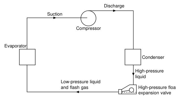
On a single-evaporator flooded system, a float valve can be fitted which will pass any drained liquid from the condenser direct to the evaporator. The action is the same as that of a steam trap. The float chamber is at condenser pressure and the control is termed a high-pressure float.
Limitations:
- The refrigerant charge is critical, since it must not exceed the working capacity of the evaporator.
- It is not possible to have a receiver in circuit.
- It cannot feed more than one evaporator, since it cannot detect the needs of either.
4.4 The shipboard high-pressure float valve
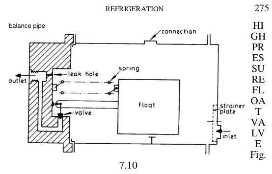
Two types of float valve are fitted, high pressure and low pressure:
- The high-pressure type as sketched is the more usual. It is fitted with the float operating in hp liquid after the condenser, with the object of draining the condenser or liquid receiver of liquid to the float level and feeding the liquid to the evaporator. The level is adjustable by altering the spring tension, and to prevent gas locking an equalising or balance pipe is usually led to the condenser top.
- The low-pressure type is to maintain a constant level of liquid in the evaporator. The valve is located with the float operating in lp liquid in the evaporator or in a separate float chamber connected to the evaporator by balance pipes. As the liquid evaporates and is drawn off, the liquid level falls and more liquid flows in to take its place.
4.5 Low-pressure receiver circuit
The difficulty of the critical charge with a high-pressure float can be overcome by allowing any surplus liquid refrigerant leaving the evaporator to spill over into a receiver or accumulator in the suction line, and boiling this off with the warm liquid leaving the condenser.
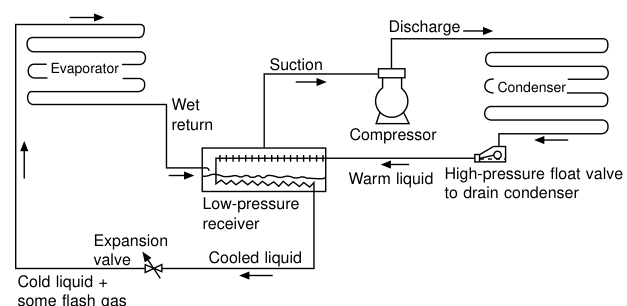
- Liquid is drained from the condenser through the high-pressure float, but the final step of pressure drop takes place in a secondary expansion valve after the warm liquid has passed through coils within the receiver.
- Two heat exchangers carry the warm liquid from the condenser within this vessel. The first coil is in the upper part of the receiver and provides enough superheat to ensure that gas enters the compressor in a dry condition. The lower coil boils off surplus liquid leaving the evaporator itself.
- With this method of refrigerant feed the evaporator has a better internal wetted surface, with an improvement in heat transfer.
- The low-pressure receiver system can be adapted to compound compression and can be fitted with hot gas defrost by reverse gas flow.
- In both circuits the low-pressure receiver provides the safety vessel to prevent liquid entering the compressor.
- Providing the high-pressure float is correctly sized, this system can operate at low condenser pressures, saving compressor energy in cool weather.
- Where halocarbon refrigerants are used in this system, an oil distillation device is fitted, working on the same principle as the R.22 oil rectifier.
4.6 Thermostatic level control
If a small heater element is placed at the required liquid level of a flooded evaporator, together with a heat-sensing element, then the latter will detect a greater temperature if liquid refrigerant is not present. This signal can be used to operate a solenoid valve.
The same principle is used in the TEV version: the phial and a heater element are both clamped to a bulb at the required liquid level. If liquid is not present, the heater warms the phial to a superheat condition and the valve opens to admit more liquid.
5. The Thermostatic Expansion Valve (TEV)
This is the valve that matters on a ship. Nearly every marine cargo and domestic plant uses it.
5.1 Why dry expansion circuits need a different control
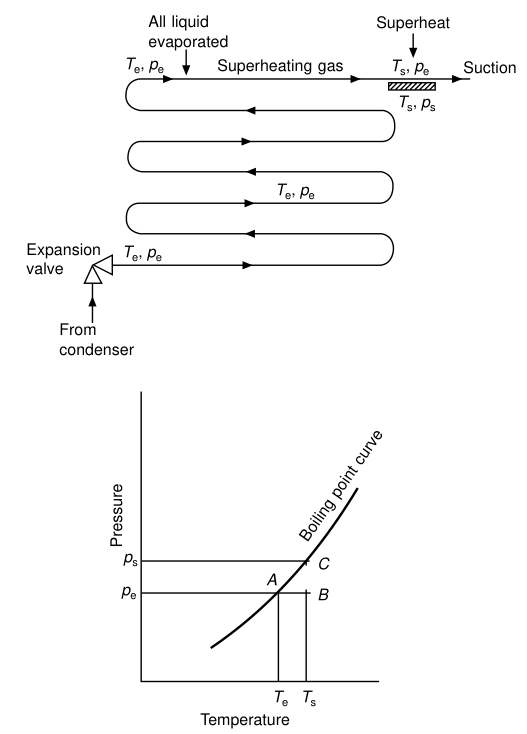
The dry expansion circuit does not have a liquid level which can be detected, and another type of signal must be used to control the valve. Dry expansion circuits must be designed and installed so that there is no risk of liquid refrigerant returning to the compressor. To ensure this state, extra heat exchange surface is added to that needed, in order to heat the dry saturated gas into the superheat region. The amount of superheat is usually of the order of 5 K.
The superheat signal, derived from first principles:
Refrigerant boils in the evaporator at Te and pe until it is all vapour, and then superheats to a condition Ts, pe, at which it passes to the suction line. A separate container of the same refrigerant at temperature Ts would have a pressure ps, and the difference ps − pe is a signal directly related to the amount of superheat.
5.2 Construction
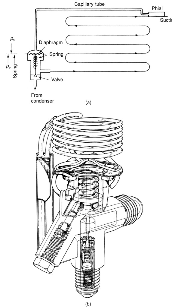
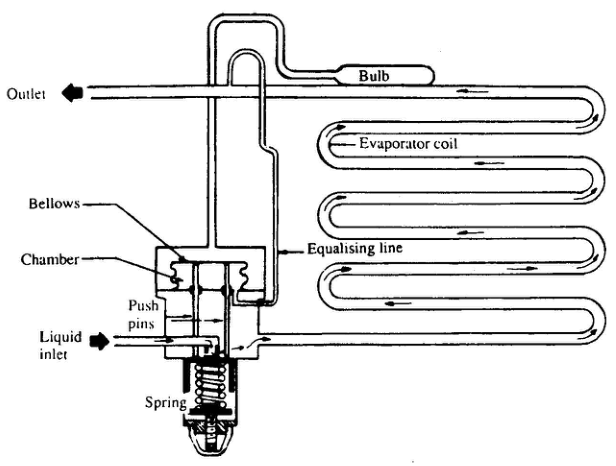
The basic thermostatic expansion valve has a detector and power element charged with the same refrigerant as in the circuit. The pressure ps generated in the phial by the superheated gas passes through the capillary tube to the top of the diaphragm. An adjustable spring provides the balance of ps − pe at the diaphragm, and the valve stem is attached at the centre.
Operation:
- Should the superheat fall for any reason, there will be a risk of liquid reaching the compressor. Ts decreases with a corresponding drop in ps. The forces on the diaphragm are now out of balance and the spring will start to close the valve.
- Conversely, if the load on the evaporator increases, refrigerant will evaporate earlier and there will be more superheat at the phial position. Then ps will increase and open the valve wider to meet the new demand.
5.3 Construction in the shipboard wording
- A small quantity of vapour refrigerant is sealed in a bulb or phial, and attached to the compressor suction pipe, just coming out from the evaporator.
- The other end is connected by a capillary tube to the chamber above the flexible bellows in the valve body.
- The space below the bellows is in communication with evaporator outlet pressure — this is called the equalising line.
- If no further action is taken, the pressure above and below the bellows will be equalised and hence no superheat is obtained.
- This is overcome by providing an adjustable bias spring under the bellows, and the bias spring pressure is proportional to the required superheat.
5.4 Operation in eight steps — the oral answer
5.5 The force balance
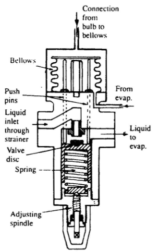
- The aperture is controlled by pressure variation on the top of a bellows, effective through the push pins, tending to open the valve against the spring. Spring pressure is set during manufacture of the valve and should not be adjusted.
- The pressure on the bellows is from a closed system of heat-sensitive fluid in a bulb and capillary connected to the top of the bellows casing.
- The bulb is fastened to the outside of the evaporator outlet, so that temperature changes in the gas leaving the evaporator are sensed by expansion or contraction of the fluid.
- Ideally the gas should leave with 6 °C or 7 °C of superheat. This ensures the refrigerant is being used efficiently and that no liquid reaches the compressor.
- Saturation temperature is related to pressure, but the addition of superheat to a gas or vapour occurs after the latent heat transaction has ended. The actual pressure at the end of the evaporator coil is produced inside the bellows by the equalising line, and this is in effect more than balanced by the pressure in the bulb and capillary acting on the outside of the bellows. The greater pressure on the outside of the bellows is the result of saturation temperature plus superheat. The additional pressure on the outside of the bellows resulting from superheat overcomes the spring loading which tends to close the valve.
5.6 Superheat settings — the numbers to remember
| Source | Setting |
|---|---|
| Welch | "usually of the order of 5 K" |
| Reed's | "usually set at about 5 °C" |
| McGeorge | "ideally 6 °C or 7 °C of superheat" |
| AJ Notes – MEP | "adjusted at 3 – 6 °C, by bias spring pressure" |
A defensible answer: the superheat is normally set between 3 and 7 °C, typically about 5 °C; the maker's figure is the one that governs. The purpose is always the same — enough superheat to guarantee that no liquid reaches the compressor, but not so much that evaporator surface is wasted.
5.7 Equalising connection
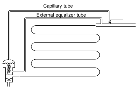
- In some plants having a large evaporator or a multi-circuit evaporator, excessive pressure drop across the evaporator occurs, and this always tends to starve the evaporator and increase the superheat.
- To counteract this, if the pressure drop across the evaporator exceeds 3 bar, an equalising connection must be provided at the TEV.
- This is a direct connection between the underside of the bellows and the suction piping of the compressor, preferably between the phial and the compressor.
Welch's version:
- The simple TEV relies on the pressure under the diaphragm being approximately the same as that at the coil outlet, and small coil pressure drops can be accommodated by adjustments to the spring setting.
- Where an evaporator coil is divided into a number of parallel passes, a distribution device with a small pressure loss is used to ensure equal flow through each pass. Pressure drops of 1–2 bar are common.
- There will now be a much larger finite difference between the pressure under the diaphragm and that at the coil inlet. To correct for this, the body of the valve is modified to accommodate a middle chamber and an equalising connection taken to the coil outlet, close to the phial position. Most TEVs will have provision for an external equaliser connection.
5.8 Phial charging and limit charging
- The phial must be larger in capacity than the rest of the power element, or the charge within it may all pass into the valve capsule and tube if these are colder. If this happened, the phial at Ts would contain only vapour and would not respond to a position Ts, ps on the T–p curve.
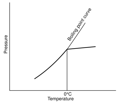
- Limit charging (maximum operating pressure): the power element can be limit charged so that all the refrigerant within it has vaporised by a predetermined temperature (commonly 0 °C). Above this point the pressure within it will follow the gas laws and the valve will remain closed. This is done to limit the evaporator pressure when first starting a warm system, which might overload the drive motor. Such valves must be installed so that the phial is the coldest part.
- The slope of the T–p curve is not constant, so a fixed spring pressure will result in greater superheat at a higher operating temperature range. To allow for this and provide a valve usable through a wide range of applications, the phial may be charged with a mixture of two or more volatile fluids to modify the characteristic curve.
Adsorption charging: some manufacturers use the principle of the adsorption of a gas by a porous material such as silica gel or charcoal. Since the adsorbent is a solid and cannot migrate from the phial, these valves cannot suffer reversal of charge.
5.9 The known weakness — hunting
The thermostatic expansion valve is substantially an undamped proportional control and hunts continuously, although the amplitude of this swing can be limited by correct selection and installation, and if the valve always works within its design range of mass flow. Difficulties arise when compressors are run at reduced load and the refrigerant mass flow falls below the valve design range.
- It is helpful to keep the condensing pressure steady, although it does not have to be constant and can usually be allowed to fall in colder weather to save compressor power.
- Valves on small systems may be seen to fully close and fully open at times.
- The continual hunting means the evaporator surface has an irregular refrigerant feed with a resulting slight loss of heat transfer effectiveness. It is probable that this valve will be superseded by the electronic expansion valve for many systems.
5.10 The pressure control type
The pressure control type expansion valve works to maintain a fixed evaporator coil pressure. It is similar to the lower part of the TEV but simpler. It consists of the liquid valve and body bellows, the body bellows being loaded by an adjustable compression spring. Up forces on the bellows (evaporator pressure) balance the hp liquid valve force down for a given setting. Evaporator pressure reduction opens the valve, pressure increase closes the valve, and when the compressor stops the rising pressure causes closure.
6. Capillary Tube
Control by capillary tube is sometimes applied in small hermetically sealed units. The small-bore capillary tube, between the cooling unit and receiver, controls the point of pressure drop between the high and low pressure sides by its length. The system is strictly tied to refrigerant quantity and capillary tube bore and length. Thus once fixed for a set loading this cannot be changed without altering the capillary tube — these limitations reduce its application.
Small domestic units are usually of the direct expansion type where the refrigerant coil is in the cold room. Such types work on constant pressure or constant superheat expansion valve control.
7. Electronic Expansion Valve
Evaporator superheat can be sensed by two thermistors — one on the main pipes of the evaporator and the other on the suction outlet — and the signal used to control refrigerant flow. The final control element is a pulsing or modulating solenoid valve.
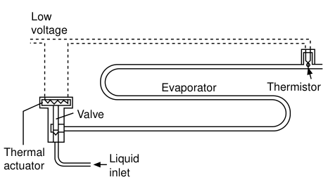
- The controller can also accept other signals, such as load temperature, discharge temperature, condensing pressure and motor current, and use these to provide optimum coil effectiveness for minimum input power.
- The electronic expansion valve has been fitted for some years on to factory-built packages but is now available for field installations, and its use will become more general.
- An integrated control circuit with an electronic expansion valve can be arranged to permit the condensing pressure to fall, providing the valve can pass the refrigerant flow required to meet the load. This gives lower compressor energy costs.
A de-energized expansion valve will act as a solenoid valve.
8. Faults, Diagnosis and Remedies
8.1 Choked expansion valve
| Item | Detail |
|---|---|
| Causes | Dirt and freeze-up of water present in the system |
| Effects | Starved evaporator; high superheat temperature; rapid condenser pressure rise can cause stopping of the compressor |
| Remedy | Clean the expansion valve and filter; renew the dehydrator |
8.2 Icing of the expansion valve — moisture in the system
Water circulating with the freon tends to freeze on the regulator, causing a build-up of pressure on the condenser side and a drop in pressure on the evaporator side due to the blockage. The machine tends to be stopped by the high-pressure cut-out.
Remedy: driers are used to remove moisture, and icing of the expansion valve indicates that the chemical is no longer effectively removing the moisture. The chemical (either activated alumina or silica gel) is renewed and the compressor restarted after the ice has melted. Usually the ice in the expansion valve will melt due to the ambient temperature.
8.3 Excessive icing up at compressor suction
Causes:
- Abnormal operation of the TEV
- Overcharge of the system
- Moisture in the system owing to a dirty drier
- Defective suction valve
8.4 Flooding of refrigerant
Seen as liquid getting back to the suction of the refrigerant compressor. It may be due to a faulty or incorrectly adjusted expansion valve and also due to solenoid valve leakage. It may also result from overcharging of the refrigeration system. Flooding may lead to an iced-up evaporator.
8.5 The diagnostic rule for superheat readings
| Reading | Meaning | Action |
|---|---|---|
| Superheat too high | Starved evaporator — valve under-feeding, choked strainer/drier, moisture ice, low refrigerant charge, phial not making good contact, phial charge lost | Check sight glass for bubbles; check drier pressure drop; clean strainer; check phial clamping and insulation |
| Superheat too low / zero | Flooded evaporator — valve over-feeding, valve held open, spring broken, phial over-charged or wrongly positioned | Check for liquid at the compressor (frost on suction, noisy compressor); check phial position and clamping |
| Superheat hunting badly | Valve outside its design mass-flow range; compressor running at low load; unsteady condensing pressure | Keep condensing pressure steady; check valve sizing against actual duty |
The phial must be clamped tightly to a clean, bare, horizontal section of the suction line, as close to the evaporator outlet as practicable, and insulated from ambient. If a suction-to-liquid heat exchanger is fitted, the phial should be located before the heat exchanger, in which case the superheat setting is reduced. It can be located after the heat exchanger, but an external equalizer is then necessary to allow for the gas pressure drop through the exchanger.