
Condensers, Evaporators and Heat Transfer
Most "the plant is not cooling" complaints are heat exchanger complaints — a dirty condenser, a frosted evaporator, an air-locked coil.
Key Principles at a Glance 5 points
- The condenser must reject the evaporator load PLUS the compressor power — there is nowhere else for that energy to go.
- Condenser rating is correctly stated as the rate of heat rejection; makers who quote the evaporator load give a de-rating factor instead, e.g. 350 × 1.22 = 427 kW.
- A separate oil cooler reduces the condenser load by the heat taken away in the oil — of special note on twin-screw compressors.
- Water carries the same heat in about 9.8 litre/s that air needs 36 m³/s to carry — which is why water cooling is preferred wherever it is available.
- A layer of scale 2 mm thick on a condenser tube can cause a power increase of 16 %, and a 15 % air flow loss from a dirty filter costs about 9 % extra power.
1. What the Engineer Must Understand
The maker's manual and the SMS override. Chemical cleaning of any heat exchanger must be to the maker's method, with all traces of chemical removed before return to service.
- The condenser must reject the evaporator load PLUS the compressor power. There is nowhere else for that energy to go.
- The evaporator is where the useful cooling is done, and its flow pattern — flooded or dry expansion — is decided by how oil is returned, not by heat transfer alone.
- Both exchangers need a temperature difference to work. The bigger they are, the smaller the difference, and the closer the plant comes to the ideal cycle. This is the single most important efficiency idea on the whole plant.
- Fouling, frost and non-condensable gas all act as insulation. They do not stop the plant, they just make it expensive — until the high-pressure cut-out stops it for you.
2. Condensers
2.1 What the condenser has to do
The purpose of the condenser is to accept the hot, high-pressure gas from the compressor and cool it to remove first the superheat and then the latent heat, so that the refrigerant will condense back to a liquid. In addition, the liquid is usually slightly subcooled. In nearly all cases the cooling medium will be air or water.
The heat to be removed, apart from comparatively small heat losses and gains through the circuit, is:
Evaporator load + compressor power = condenser load
This latter, again ignoring small heat gains and losses, is the net shaft power into the compressor. Condenser rating is correctly stated as the rate of heat rejection. Some manufacturers give ratings in terms of the evaporator load together with a de-rating factor depending on the evaporating and condensing temperatures:
Evaporator load × factor = condenser load
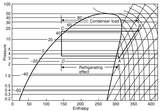
A condenser manufacturer gives a heat rejection capacity factor of 1.22 at 26 °C wet bulb. What is the condenser duty if the cooling capacity is 350 kW?
Condenser duty = 350 × 1.22 = 427 kW.
Note: the provision of a separate oil cooler will reduce condenser load by the amount of heat lost to the oil and removed in the oil cooler. This is of special note with twin-screw compressors, where a high proportion of the compressor energy is taken away in the oil. Figures should be obtained from the compressor manufacturer for a particular application.
2.2 Air-cooled condensers
- The simplest consists of a plain tube containing the refrigerant, placed in still air, relying on natural air circulation — e.g. the condenser of the domestic refrigerator, which may also have some secondary surface in the form of supporting and spacer wires.
- Above this size, air flow is by forced convection (fans). The high thermal resistance of the boundary layer on the air side leads to the use, in all but the very smallest condensers, of an extended surface — plate fins mechanically bonded onto the refrigerant tubes. Ratio of outside to inside surface between 5:1 and 10:1.
- Flow of the liquefied refrigerant is assisted by gravity, so the inlet is at the top and the outlet at the bottom. Rising pipes should be avoided and pipes should be installed level.
- Forced convection of large volumes of air at low resistance leads to the general use of propeller or single-stage axial flow fans. Where a single fan would be too big, multiple smaller fans give lower tip speed and noise, and flexibility of operation in winter. In residential areas slower-speed fans may be specified to reduce noise, but a smaller air flow will de-rate the condenser.
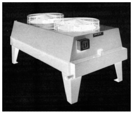
The air-side numbers:
- The low specific heat capacity and high specific volume of air imply a large volume to remove the condenser heat.
- If the mass flow is reduced, the temperature rise must increase, raising the condensing temperature and pressure, and giving lower plant efficiency.
- In practice the temperature rise of the air is kept between 9 and 12 K. At 10.5 K the mass flow is 1 / (10.5 × 1.02) = 0.093 kg/(s·kW), where 1.02 is the specific heat capacity of ambient air.
- Example: an air-conditioning condenser for a small office block, cooling capacity 350 kW, rejecting 430 kW, would need 40.85 kg/s, or about 36 m³/s of air.
- The cooling air should be as cold as possible, so the condenser needs to be mounted where such a flow of fresh ambient air is available without recirculation.
- The large air flows needed, the power to move them, and the resulting noise levels are the factors limiting the use of air-cooled condensers.
Materials: aluminium fins on stainless steel tube for ammonia; aluminium or copper fins on aluminium or copper tube for the halocarbons.
Performance penalty: in view of the high material cost, a higher log mean temperature difference is usually accepted, and condensing temperatures may be 5–8 K higher for a given cooling medium temperature. Air-cooled condensers must be used on land transport systems and in desert areas where the supply of cooling water is unreliable.
Reed's adds: air-cooled condensers are only used for small domestic units; they usually have finned tubes and air circulation may be fan assisted.
2.3 Water-cooled condensers
The higher heat capacity and density of water make it an ideal medium for condenser cooling. By comparison with the 350 kW air-cooled plant above, the water flow is only 9.8 litre/s.
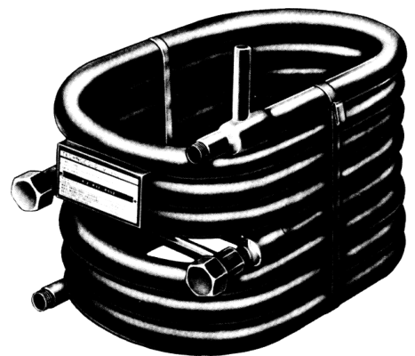
- Small water-cooled condensers may comprise two concentric pipes ("double pipe"), refrigerant in either the inner tube or the annulus. Configurations may be straight with return bends or headers, or coiled. The double-pipe condenser is circuited in counterflow so that the coldest water meets the outgoing liquid refrigerant, to get the most subcooling.
- Larger sizes require closer packing of tubes, and the general form is shell-and-tube, having the water in the tubes.
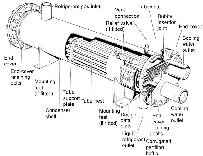
- Shell-and-tube is a very adaptable mechanical design, found in all sizes from 100 mm to 1.5 m diameter and in lengths from 600 mm to 6 m.
- Materials: all mild steel is common for fresh water, with cupronickel or aluminium brass tubes for salt water.
- Some economy in size is effected by extended surfaces on the refrigerant side — usually low integral fins on the tubes. On the water side, swirl strips promote turbulence, but these interfere with maintenance cleaning and are not much in favour.
- Water velocity within the tubes is of the order of 1 m/s, depending on bore size. To maintain this velocity, baffles are arranged within the end covers to direct the water flow to a number of tubes in each "pass".
- Some condensers have two separate water circuits (double bundle), using the warmed water from one circuit as reclaimed heat in another part of the system; the main bundle rejects the unwanted heat.
- Where the mass flow of water is unlimited (sea, lake, river or cooling tower), the temperature rise through the condenser may be kept as low as 5 K, since this reduces the log mean temperature difference with a lowering of head pressure, at the cost only of larger water pumps and pipes.
2.4 The marine shell-and-tube condenser
Reed's describes the shipboard freon condenser in constructional terms:
- Virtually all are of the shell and tube type. The shell is welded construction of mild steel with vapour inlet, purge, drain and liquid outlet connections on the main body.
- The vapour condenses on the outside of the tubes and falls to the lower part of the condenser, which commonly acts as the liquid receiver.
- The water flow is multi-pass (usually 2, 4 or 8 flow types, so keeping inlet and outlet branches at one end) through cast iron end covers.
- Tube plates are either ferrous, of welded mild steel, with steel tubes expanded into place, or non-ferrous, of muntz metal with aluminium brass expanded tubes.
- Galvanic protection blocks (zinc or iron) should be provided, and steel tube plates are best treated with chromium for corrosion resistance.
- Temperature differences are not high and the little expansion can be taken up by metal resilience.
- Non-ferrous metals are attacked by ammonia refrigerant — this means all jointing of lead or soft iron and the use of steel tubing.
McGeorge adds: heat transfer is sometimes improved by rolling threads on the outsides of the tubes.
2.5 Water cooling towers
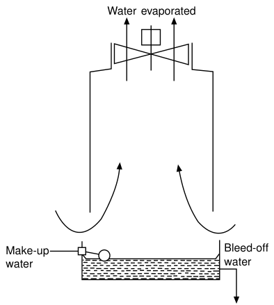
Where water is evaporated from a circuit — a cooling tower, an evaporative condenser or a humidifier — it must be remembered that there is no way of avoiding a steady bleed-off or frequent flushing, to restrict the concentration of dissolved solids. Much trouble arises from the efforts of well-wishing but misguided persons who stop the flow of bleed-off to "save water".
Tower-specific points:
- Where evaporative condensers and water cooling towers have only one fan (or fan drive motor), coarse control can be effected by on–off switching. The time lag then depends on the mass of water in the circuit, and the sensing element needs a wide differential to prevent frequent motor starts.
- Towers should have thermostatic control of the fan to prevent water freezing on the packing in winter.
- Water tower strainers will not remove all the dirt. The larger particles will fall to the bottom of the sump and must be flushed out, possibly twice a year.
- Water towers should be drained in winter if not in use, and the tank heater disconnected.
3. Evaporators
3.1 What the evaporator has to do
The purpose of the evaporator is to receive low-pressure, low-temperature fluid from the expansion valve and bring it in close thermal contact with the load. The refrigerant takes up its latent heat from the load and leaves the evaporator as a dry gas.
Evaporators are classified according to their refrigerant flow pattern and their function:
- Flow pattern is dependent on the method of ensuring oil removal from the evaporator and, possibly, its return to the crankcase.
- Flooded evaporators — a body of fluid boiling in a random manner, the vapour leaving at the top.
- Dry expansion evaporators — the oil is kept moving by continuous fluid velocity until it gets back to the compressor suction; in these the refrigerant is totally evaporated.
- Function is to cool a gas, liquid or other product load. In most cases air or a liquid is first cooled and this is then used to cool the load — e.g. in a coldroom air is cooled and the air cools the stored produce and carries away heat leaking through the structure; in a water chiller the water is circulated to cool the load.
3.2 Air-cooling evaporators
- For coldrooms, blast freezers and air conditioning, these have finned pipe coils. In all but very small coolers there will be fans to blow the air over the coil.
- Materials: the same as for air-cooled condensers — aluminium fins on copper tube for the halocarbons; stainless steel or aluminium tube for ammonia.
- Frost or condensed water will form on the fin surface and must be drained away. To permit this, fins are vertical, air flow is horizontal, and a drain tray is provided underneath.
- Tube diameter is chosen so that the velocity of the boiling fluid within it causes turbulence to promote heat transfer — from 9 mm to 32 mm, according to the size of coil.
- Fin spacing is a compromise between compactness (and cost) and the tendency for the interfin spaces to block with condensed moisture or frost — from 2 mm on a compact air-conditioner to 12 mm on a low-temperature coldroom coil.
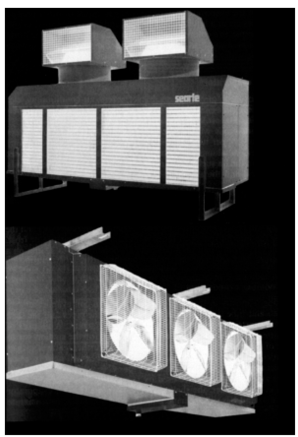
This is the design reason the low-temperature coil frosts faster and is harder to defrost — wide fin spacing gives it somewhere for the frost to go, but the fin area is lower.
3.3 Liquid-cooling evaporators
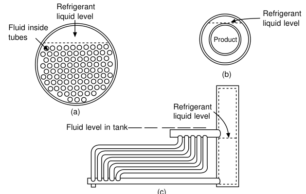
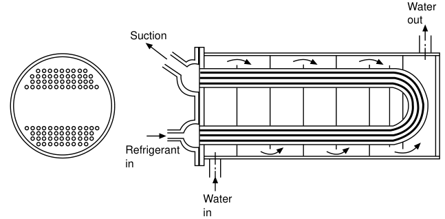
Shell-and-tube, flooded:
- The liquid is usually in the pipes and the shell is some three-quarters full of the boiling refrigerant.
- A number of tubes is omitted at the top of the shell to give space for the suction gas to escape clear of the surface without entraining liquid. Further features such as multiple outlet headers, suction trap domes and baffles help avoid liquid droplets entering the main suction pipe.
- Gas velocities should not exceed 3 m/s and lower figures are used by some designers.
- Has oil drainage pots if using ammonia, or a mixture bleed system if the refrigerant is a halocarbon.
- The speed of the liquid within the tubes should be about 1 m/s or more, to promote internal turbulence for good heat transfer.
- End cover baffles constrain the flow to a number of passes, as with the shell-and-tube condenser.
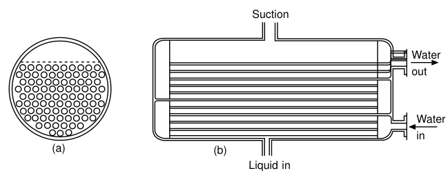
Shell-and-tube / shell-and-coil, dry expansion:
- Evaporators of this general type with dry expansion circuits will have the refrigerant within the tubes, in order to maintain a suitable continuous velocity for oil transport, and the liquid in the shell.
- Can be made as shell-and-tube, with the refrigerant constrained to a number of passes, or shell-and-coil. In both configurations baffles are needed on the water side to improve turbulence, and the tubes may be finned on the outside.
- Internal swirl strips or wires will help to keep liquid refrigerant in contact with the tube wall.
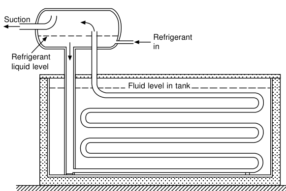
Tank and open-tank evaporators:
- Liquid cooling evaporators may comprise a pipe coil in an open tank, with flooded or dry expansion circuitry.
- Flooded coils are connected to a combined liquid accumulator and suction separator (usually termed the surge drum), in the form of a horizontal or vertical drum. The expansion valve maintains a liquid level in this drum and a natural circulation is set up by the bubbles escaping from the liquid refrigerant at the heat exchanger surface.
- Dry expansion coils for immersion in an open tank are in a continuous circuit or a number of parallel circuits. Liquid velocity over such coils can be increased by tank baffles, and there may be special-purpose agitators, as in an ice-making tank.
- Coils within an open tank can be allowed to collect a layer of ice during off-load periods, thus providing thermal storage and giving a reserve of cooling capacity at peak load times.
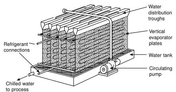
Baudelot cooler — where water is to be cooled close to its freezing point without risk of damage to the evaporator, the evaporator is arranged above the water-collection tank and a thin film of water runs over the tubes. Heat transfer is very high with a thin moving film of liquid, and if any ice forms it will be on the outside, free to expand, and will not damage the tube. It may be open, enclosed in dust-tight shields to avoid contamination of the product (as in surface milk and cream coolers), or enclosed in a pressure vessel as in the Mojonniér cooler for soft drinks, which pressurises with carbon dioxide at the same time.
Scraped-surface (hollow drum) evaporators — for liquids such as vegetable fats and ice-cream mixes which increase considerably in viscosity as they are cooled and stick to the heat exchanger surface. The evaporator is a hollow drum surrounded by the refrigerant, with internal rotating blades which scrape the product off as it thickens, presenting a clean surface to the flow of product and impelling the cold paste towards the outlet.
3.4 Plate evaporators
Formed by cladding a tubular coil with sheet metal, welding together two embossed plates, or from aluminium extrusions. The extended flat face may be used for air cooling, liquid cooling if immersed in a tank, or as a Baudelot cooler.
The major use is to cool a solid product by conduction, the product being formed in rectangular packages and held close between a pair of adjacent plates:
- Horizontal plate freezer — plates arranged in a stack on slides so that intermediate spaces can be opened and closed. Trays, boxes or cartons are loaded between the plates and the stack is closed to give good contact on both sides. When cooling is complete, the plates are opened and the product removed.
- Vertical plate freezer — used to form solid blocks of a wet product, typically fish. When frozen solid, the surfaces are thawed and the blocks pushed up and out of the bank.
- To ensure good heat transfer on the inner surface and a high rate of usage, liquid refrigerant is circulated by a pump at a rate 5–12 times the rate of evaporation.
- If a plate evaporator is partially filled with brine, this can be frozen down while the plate is on light load and the reserve of cooling capacity used at other times. The freezing point of the brine can be formulated for the application and the plate made as thick as required for the thermal storage needed. The major application is the cooling of vehicles — the plates are frozen down at night or when the vehicle is not in use, and the frozen brine keeps the surface cold while the vehicle is on the road.
3.5 The shipboard evaporator
Each cold room used for domestic stores will have an evaporator which cools air blown through it by a fan. The air acts as a secondary refrigerant by circulating through and cooling the stores. Such an arrangement is termed a direct expansion system. Many cargo installations operate on the same principle.
There is a risk with direct expansion that a leakage of gas will occur into the cargo space, and brine is used to circulate the air cooling coils in some cargo spaces. The evaporator is then a brine cooler and the brine is pumped through the air cooling grids in the cold rooms.
Reed's adds: modern evaporator grid types are only used on small plants, and the distance between supply and return headers is very short, so giving quick maximum extraction of vapour formed. Large evaporators are invariably of the shell and tube type, almost identical to condensers in design and construction. Brine circulates through the tubes in multi-pass flow and the vapour–liquid mixture enters at the bottom at one end. The evaporated vapour leaves at the top of the other end, so that speedy vapour extraction, full heat flow and full evaporation are achieved.
4. Heat Transfer Theory — the Revision the Oral Expects
4.1 Log mean temperature difference
The two examples below serve to revise basic theory.
Example 1. A liquid refrigerant evaporates at 3 °C and cools water from 11.5 °C to 6.4 °C in a heat exchanger of cooling surface area 360 m² for which the overall heat transfer coefficient is 100 W/m²K. Evaluate the log mean temperature difference and the heat transfer rate.
Δθ₁ = 11.5 − 3.0 = 8.5 K
Δθ₂ = 6.4 − 3.0 = 3.4 K
LMTD = (8.5 − 3.4) / ln(8.5 / 3.4) = 5.566 K
Q = 100 × 5.566 × 360 = 200 376 W
Example 2. Calculate the effectiveness of a heat exchanger which cools air from 25 °C to 15 °C with refrigerant evaporating at 5 °C.
4.2 Air-side calculations for cooling coils
The heat exchanger is the same physics whether condensing or evaporating: the surface area, the overall coefficient and the log mean temperature difference multiply to give the duty.
4.3 Effect of reduced air flow — the dirty-filter calculation
This is one of the most valuable worked examples in the whole subject, because a dirty air filter is by far the most frequent cause of malfunction of air-conditioning equipment.
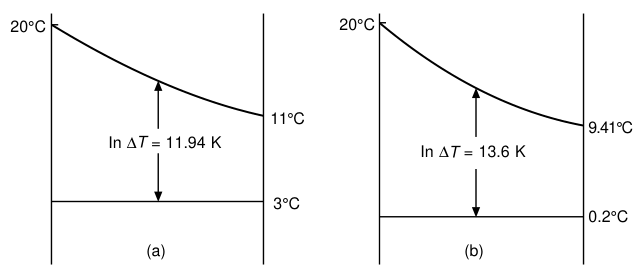
An R.22 direct expansion coil evaporates at 3 °C when cooling air from 20 °C to 11 °C. Condensing is at 35 °C. If the air flow is reduced by 15 % because of a dirty filter, what is the approximate increase in running cost?
Air entering coil                              = 20 °C
Air off coil at full air flow                  = 11 °C
Evaporating temperature at full air flow       = 3 °C
ln MTD at full air flow = (17 − 8) / ln(17/8)  = 11.94 K

Air off coil at 85 % air flow = 20 − (20 − 11)/0.85 = 9.41 °C
Coil performance at 85 % air flow = (0.85)^0.8 = 0.88
ln MTD at 85 % air flow = 11.94 / 0.88 = 13.6 K

The evaporating temperature will now fall to about 0.2 °C.
Compressor tables show 10.3 % loss in duty for 1.5 % less power
at the new condition — an overall power increase of 9 %.
The operational lesson: a 15 % air flow loss costs about 9 % extra power, and it happens silently. Manometers across filters give a positive indication of the need to clean or replace. Such resistances can be estimated from the filter manufacturer's data and should be recorded at the time of commissioning and also marked at the filter.
5. Defrosting
Air cooling evaporators working below 0 °C will accumulate frost which must be removed periodically, since it will obstruct heat transfer.
5.1 Why defrosting is necessary
Defrosting should be done before snow thickness exceeds ¼ inch.
Reasons for defrosting:
- Affecting heat transfer properties.
- Affecting air flow and circulation.
- Liquid back to compressor — a frosted coil reduces superheat, so the TEV closes in, so the evaporator starves, so the compressor may draw liquid.
McGeorge puts the mechanism precisely: frost on the evaporator coils reduces the efficiency of the plant by acting as an insulator between the evaporator and the air in a direct expansion system. The air flow is also restricted by the blockage. Automatic defrosting keeps the coils free of ice, but failure of the defrost arrangement allows excessive icing. The result is that cold room temperature gradually rises and the compressor runs continuously at first. Later the compressor will cut out as the result of low suction pressure, and then restart as the refrigerant passing through the still open solenoid builds up pressure. Suction pressure is low because the thermostatic valve, controlled by the evaporator gas outlet temperature (which due to icing will be low), will reduce refrigerant flow.
Removal: ice on the evaporator can be removed by washing it off with a hot water hose with the plant shut down, after clearing the drip tray drain if necessary.
5.2 Defrosting systems
Shipboard list:
- Water wash defrosting
- Hot gas defrosting
- Electric defrosting
- Manual shutdown defrosting
- Warm brine defrosting
Methods by system type:
| System | Defrost method |
|---|---|
| Direct expansion grid system | Hot gas defrosting |
| Battery cooling system | Water spray, electrical or steam heater |
| Brine cooling | Hot brine thawing |
5.3 Brine system defrosting — three methods compared
5.4 Cargo fridge defrosting (battery system)
In the battery system, hot brine passing through a brine heater is used. Steam is released to the brine heater and the brine flow is restricted by the brine inlet valve, until the brine temperature has risen above 0 °C. A brine temperature of 43 °C is suitable for defrosting.
5.5 Cold room defrosting
The coil is required to be defrosted to gain more heat transfer efficiency. Methods:
- Plant stopped and manual watering
- Hot gas circulating
- Electric heater
McGeorge adds the automatic arrangement: regular defrosting by means of electric heating elements keeps the evaporator free from ice. The time switch de-energizes the solenoids to shut down the system and supplies the power to the heaters instead.
6. Heat Exchanger Cleaning — the Maintenance That Pays
- The correct and efficient operation of any plant requires full flow at all times through the heat exchangers. Air and water filters need to be kept clean. Finned coils, especially outdoor condenser coils, must be cleaned frequently.
- The water side of heat exchanger coils should be cleaned of any accumulations of scale or algae as soon as a change in working conditions shows that they are getting dirty.
- Accumulated dirt on air filters will increase the resistance and lead to reduced air flow. This is by far the most frequent cause of malfunction of air-conditioning equipment.
- Aqueous circuits (evaporator or condenser) can be cleaned with a chemical such as sulphamic acid, brushed, or subjected to high-pressure water jets. In each case all traces of dirt and chemical need to be removed from the circuit before it is put back to work. In cases of doubt, the manufacturer's advice should be sought.
- A layer of scale 2 mm thick on a condenser tube can cause a power increase of 16 %, and the need to clean a condenser can usually be deduced from the condensing pressure.
- Persons using high-pressure water jets should wear face masks to avoid inhaling aerosol droplets.
- Heat exchange would be reduced by oil deposits in condensers (and evaporators), but this is not usually a problem when suitable oils are used. Oil carry-over is cut down by the separators fitted on some compressor discharges. Oil deposit is removed by chemical cleaning.
If the condensing pressure is rising and the cooling water is clean and flowing, suspect fouling, scale or non-condensables — in that order of likelihood.