
Oil in Refrigerant Systems
The component most often neglected and the one that causes the most subtle faults — oil that stays in the compressor is doing its job.
Key Principles at a Glance 5 points
- Oil has three jobs — reduce friction, remove frictional heat, and seal between the compression stages; the type is chosen so as not to react with the refrigerant.
- Miscibility decides everything: ammonia is non-miscible so oil sinks and must be drained by hand weekly or even daily; halocarbons are miscible so oil must be carried back by gas velocity.
- The critical section of a dry expansion circuit is where no liquid refrigerant is left to move the oil — the evaporator outlet and suction pipe — and it needs 5–7 m/s of entrainment velocity.
- Pour point applies to all oils, but floc point only to oils in freon systems — the temperature at which wax precipitates from a 10 % solution of oil in freon.
- Feel the oil return line from the separator: warm is normal; cold means liquid refrigerant is vaporising in it and carrying over.
1. What the Engineer Must Understand
The maker's manual and the SMS override. Only the manufacturer's prescribed oil may be used. Only clean oil from sealed containers may be used. No refrigerant is allowed to be released to atmosphere.
The behaviour of lubricating oil in a refrigerant circuit and its physical interaction with the refrigerant itself is a dominant factor in the design of circuits in general and evaporators in particular.
Why the compressor needs oil at all:
Refrigeration compressors are mechanical devices with component parts which slide together, so requiring lubrication to reduce friction, remove frictional heat and assist with gas sealing.
The shipboard statement of oil's three functions:
The compressor's own three reasons for lubrication:
- Reduce the frictional wear on bearings and moving parts
- Cool the refrigerant gas during compression
- Seal against refrigerant gas leakage
The critical concept: miscibility. Whether the oil dissolves in the liquid refrigerant or separates out decides the whole oil-return strategy. Oil that is in solution does not settle out on to surfaces, but oil that is not miscible collects at the lowest point and must be drained manually.
2. Oil Specification
2.1 Required properties
Lubricants for general commercial systems are based on mineral oils, and the following properties are required of the lubricant selected:
A large variety of oils is available; recommendations for any set of conditions, compressor type and refrigerant can be obtained from the refiners. They are naphthene or paraffin-based oils. Synthetic lubricants have been developed for ultra-low- and high-temperature systems, especially for process heat pumps.
2.2 Shipboard properties
The refrigeration compressor lube oil should have:
- Outstanding low-temperature fluidity
- Outstanding oxidation resistance and thermal stability at high temperatures
- Excellent deposit control
- Low volatility for lower oil consumption and less make-up oil
- Protection against rust and corrosion
Preferred specification:
| Property | Value |
|---|---|
| ISO Viscosity Grade | 68 |
| Viscosity Index | 143 |
| Density @ 15 °C, g/cm³ | 830 |
| Flash Point, °C | 230 |
| Viscosity at 40 °C, cSt | 70 |
| Pour Point, °C | −42 |
2.3 Typical analysis and the reason for a low pour point
| Property | Value |
|---|---|
| Density | 900 kg/m³ |
| Flashpoint | 235 °C |
| Viscosity | 12 cSt at 50 °C |
| Pour point | −42 °C |
The first essential for such an oil is that it should have a low pour point — i.e. it must remain fluid with good lubrication properties at low temperatures.
- Oils which are miscible with the refrigerant can be carried round the circuit and could congeal on the evaporator coils, so drastically reducing heat transfer rates.
- The oil should be free from moisture under all conditions, to prevent plant corrosion and freezing at the expansion valve.
- The viscosity should not be seriously affected at low temperature.
- A pure mineral oil is advised (Arctic, Seal oil, etc.). The above is suitable for reciprocating compressors.
- Compressors should not be run too hot, otherwise there is a danger of oil vaporisation and subsequent ignition by the heat of compression.
2.4 Oil classification
The lubricating substances could be divided into natural mineral oils, synthetic oil and half-synthetic oil. The mineral oils could further be divided into:
- oils with a small amount of aromatic hydrocarbons, known as paraffin oils;
- oils with a majority of aromatic hydrocarbons, known as naphthalene oils;
- oils with a majority of aromatic hydrocarbons supplemented by groups of simple or alkyl rings.
Practical selection rule: a naphthenic oil may be used for low temperatures. These have generally a lower pour point than the corresponding grades of paraffinic oils. Either may be used because they are refined and dewaxed to the lowest pour point possible, and pour point depressants are also used as additives.
2.5 How the oil behaves inside the compressor
In the cylinder of a positive displacement compressor, where the lubricating substance is used for sealing, cooling and lubricating, during the lubricating of the cylinder's smooth surface an oil film emerges on the cylinder wall. A partial dispersion of lubricating substance takes place in the working space of the compressor, resulting in the appearance of an aerosol.
As a consequence of the piston's forward–backward movement and its friction against the cylinder wall, the wall's temperature rises. If the temperature is high enough, the wall "dries out". The oil takes over the heat from the cylinder wall (cooling function) and turns into vapour. In the compressor cylinder a structure of flux of the air and lubricating substance mixture in the form of liquid, steam and aerosol emerges.
The type of oil is chosen so as not to react with the refrigerant type and other components in the system.
3. Pour Point against Floc Point
| Term | Applies to | Definition |
|---|---|---|
| Pour point | All oils | The lowest temperature at which the oil will still flow |
| Floc point | Oils in freon systems only | The temperature at which wax precipitates out of a solution of oil in freon |
Floc point explained: cooling of oil in solution with freon causes a wax to precipitate initially to produce a cloudy appearance and finally as crystals of wax. In this state the wax is called a flocculant, hence the term floc point. Tests for wax precipitation are carried out with a 10 per cent solution of oil in freon, which is cooled until wax appears; the temperature at which this occurs is the floc point. Flocculation in a system can cause wax to deposit on regulating valves and interfere with operation.
In the source's own words:
Pour point applies to all oils but floc point to oils in freon systems.
Why the distinction matters: Freon 12 is miscible with oil at the working temperatures and pressures in the system, and the pour point of the mixture tends to be lower than the evaporator temperature. Oil pour point is therefore less important in an installation using R 12 than in those using a refrigerant which is not miscible such as CO₂. Because the oil is in solution it does not settle out on to surfaces. When the refrigerant boils off in the evaporator the agitation and velocity of the gas carries the oil mist along to the compressor suction.
Oil viscosity is important because of the variation produced by miscibility with the gas.
4. Miscibility and Density — the Table That Decides the Oil-Return Strategy
| Refrigerant | At 0 °C | At 35 °C | Specific mass (kg/m³) |
|---|---|---|---|
| R134a | Fully miscible | Fully miscible | 1295 |
| R.22 | Separates into oil-rich mixture at top and refrigerant-rich mixture at bottom | Fully miscible | 1177 |
| R.717 ammonia | Non-miscible | Non-miscible | 596 |
| Oil | — | — | 910 |
The extent of miscibility and the consideration of liquid density divides the problem of oil separation and circulation into two distinct classes.
4.1 Ammonia — non-miscible
With ammonia, oil sinks to the bottom and does not go into solution with the refrigerant. Ammonia condensers, receivers and evaporators can be distinguished by the provision of oil drainage pots and connections at the lowest point. Automatic drainage and return of the oil from these would have to depend on the different densities, and is very rarely fitted. The removal of oil from collection pots and low-point drains is a periodic manual function and is carried out as part of the routine maintenance.
Ammonia systems, even those with the most sophisticated separators, have continuous oil migration and require attention every week or, in some cases, every day, to ensure maximum working efficiency. Plant operators need to be well trained and practised in this simple maintenance task, to minimize loss of refrigerant. In larger plants, the oil removed can be filtered and used again. It is useful to enter in the running log the quantities of oil removed and put in, since it has been known for large amounts of oil to accumulate in an evaporator without operators being aware of it.
4.2 Halocarbons — miscible, so oil is returned by velocity
The halocarbons are all sufficiently miscible with oil to preclude the possibility of separate drainage in this way. Two strategies exist:
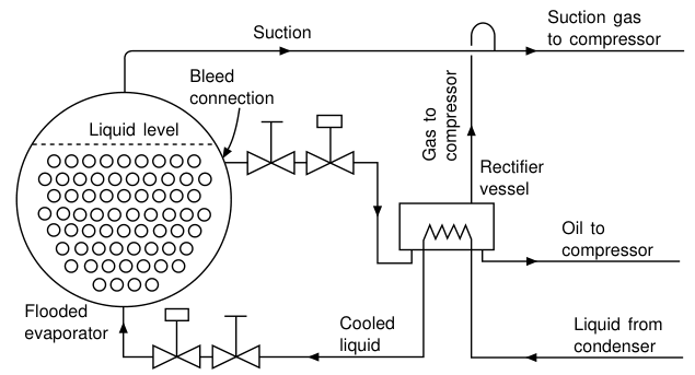
(a) R.22 flooded evaporators — bleed and rectify. Evaporators containing a large body of R.22 will have a greater concentration of oil in the upper layers. By bleeding off a proportion of the mixture (about 10 % of the mass flow) and separating the oil from this by distillation, the concentration can be held to an acceptable working limit. Since the addition of outside heat for this distillation would be a direct waste of energy, the heat is obtained from the warm liquid passing from the condenser to the expansion valve.
(b) Dry expansion circuits — keep the oil moving. The alternative method of returning oil from the evaporator to the compressor is to keep it moving by ensuring a minimum continuous fluid velocity in all parts of the circuit. This is termed the dry expansion circuit. This dynamic circulation method is the decisive factor in the design of nearly all halocarbon evaporators, the exceptions being "flooded" evaporators.
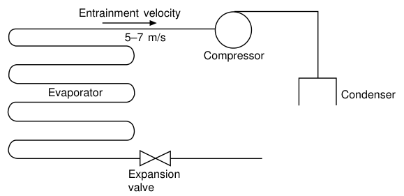
The numbers to remember: the critical section of the circuit is where there is no liquid refrigerant left to help move the oil — i.e. the evaporator outlet and the suction pipe back to the compressor. Entrainment velocities of 5–7 m/s are required to ensure that oil droplets will be carried back by the dry refrigerant gas to the compressor.
- The principle of continuous fluid velocity means that the evaporator will be in a continuous circuit. This does not imply that it has to be one pipe, since many pipes may be arranged in parallel to get the required heat transfer surface, providing the minimum velocity criteria are met.
- Some small cooling circuits have reversing refrigerant flow (cooling/heat pump) and may work at reduced gas flow for capacity control. Under such conditions it may not be possible to maintain the minimum velocity to carry oil back to the compressor, and it will settle in the circuit. Arrangements must be made to increase or reverse the gas flow periodically to move this oil.
- Migration of oil over a long period in a dry expansion circuit should be treated as a design fault, and some action taken to put it right.
Where halocarbon refrigerants are used in a low-pressure receiver system, an oil distillation device is fitted, working on the same principle as the R.22 rectifier.
5. Oil Separators
5.1 Why an oil separator is fitted
During the compression stroke of a reciprocating machine, the gas becomes hotter and some of the oil on the cylinder wall will pass out with the discharge gas. To reduce the amount of this oil which will be carried around the circuit, an oil separator is frequently fitted in the discharge line.
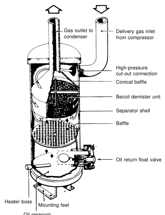
Some 95–98 % of the entrained oil may be separated from the hot gas and fall to the bottom of the drum, and can be returned to the crankcase. The hot entering gas is made to impinge on a plate, or may enter a drum tangentially to lose much of the oil on the surface by centrifugal force.
The oil return line will be controlled by a float valve, or may have a bleed orifice. In either case this metering device must be backed up by a solenoid valve to give tight shut-off when the compressor stops, since the separator is at discharge pressure and the oil sump at suction.
The dilution problem and the heater: on shut-down, high-pressure gas in the separator will cool and some will condense into liquid, to dilute the oil left in the bottom. When the compressor restarts, this diluted oil will pass to the sump. In order to limit this dilution, a heater is commonly fitted into the base of the separator.
Two-stage separators: for installations which might be very sensitive to accumulations of oil, a two-stage oil separator can be fitted. The second stage cools the gas to just above condensing temperature, and up to 99.7 % of the entrained oil can be removed. Even so, a small quantity will be carried over.
Note for screw and sliding-vane machines: sliding vane and screw compressors may have extra oil injected into the casing to assist with sealing, and this must be separated out and re-cooled.
5.2 The shipboard description of the separator
To enable the oil ejected from the compressor to return to the crankcase, it is necessary:
- to respect the speed in the pipes in order to ensure the circulation of oil — especially when the refrigerant is in the gas stage, as its miscibility with oil is low;
- to use an oil separator, whose function is to recover a substantial quantity of oil and to make it return to the compressor as soon as possible.
In small refrigeration systems, the oil is allowed to circulate throughout the whole circuit, but care must be taken to design the pipework and components such that oil can drain back under gravity to the compressor. In larger more distributed systems, especially in retail refrigeration, oil is normally captured at an oil separator immediately after the compressor, and is in turn re-delivered, by an oil level management system, back to the compressor(s).
5.3 The four separation techniques
| Technique | Principle |
|---|---|
| Coalescence | The phenomenon in which two substances, identical but separated, tend to concentrate |
| Centrifugation | Uses centrifugal force to separate refrigerants with different densities |
| Speed reduction | Enables the heaviest molecules to follow their trajectory by inertia, while the lightest molecules scatter into the internal volume of the oil separator |
| Change of direction | In association with the previous technique, improves the efficiency of droplet separation (heavy molecules) present in the steam (light molecules). The droplets keep their initial trajectory because of their mass and initial speed, while steam is directed towards the outlet connection |
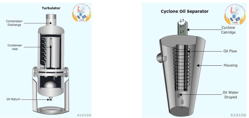
Manufacturers of oil separators select one or several separation techniques according to the level of efficiency required. Coalescence can be obtained with metallic sieves or coalescent cores which will then need to be replaced regularly.
5.4 How an oil separator works — the mechanism, step by step
5.5 The oil return line — a diagnostic indicator you can feel
The oil return line from the oil separator to the crankcase should be just above room (ambient) temperature. This is caused from heat conduction to the line from the hot oil separator. If the oil return line is cool or cold to the touch, there may be liquid refrigerant vaporizing in it as it passes oil. This problem can result from the oil separator's shell being poorly insulated and becoming too cool. If the shell is too cool, it can cool discharge gases too much, resulting in condensed (liquid) refrigerant in the bottom of the oil separator. This will cause the float to rise too often because of increased levels of an oil and liquid refrigerant mixture in the bottom of the separator.
Once the float rises and the orifice opens, the mixture of liquid refrigerant and oil passes through the oil return line. The liquid refrigerant will vaporize from the sudden pressure drop and cause the cool temperatures in the return line.
This is a first-class practical check: feel the oil return line. Warm is normal. Cold means liquid refrigerant is carrying over.
6. The Oil Trap
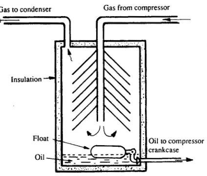
Cylinder walls are splash lubricated and some of the oil is carried around with the refrigerant. A float-controlled oil trap may be fitted to reduce carry-over from the larger machines, but they are not always considered necessary.
- When used, the oil trap is fitted in the discharge pipe close to the compressor.
- The heat of the freon must be retained to prevent it from condensing and returning with the oil to the compressor crankcase. Thus the casing is insulated.
- Oil and refrigerant enter the trap by a pipe which runs down towards the bottom. The gas leaving this pipe changes direction but the heavier oil tends to drop to the bottom.
- The float rises as the oil collects, lifting a valve which allows the oil to be fed back to the compressor sump.
- Operation is improved by fitting a demister or scrubber unit.
7. The Oil Rectifier
In some installations there may be a problem caused by a tendency for oil to collect in the evaporator under certain conditions — such as at low load, when the speed of movement and agitation of the evaporating refrigerant are insufficient to keep the oil moving. To prevent loss of oil from the sump to the system, an oil rectifier may be fitted.
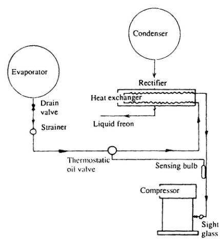
How it works:
- The oil is automatically bled from the evaporator to a heat exchanger in which liquid refrigerant mixed with the oil is vapourized.
- The heat for vapourizing the refrigerant is obtained by passing warm liquid freon from the condenser through the heat exchanger.
- Vapour and oil are passed to the compressor, where the oil returns to the sump while the freon passes to the compressor suction.
- The regulator is a thermostatically controlled valve which operates in the same way as the expansion valve on the main system. It automatically bleeds the oil from the evaporator so that the gas leaves the rectifier heat exchanger in a superheated condition.
The advantage over the oil trap: the rectifier acts automatically, whereas the trap is float-operated and mechanical.
8. Oil Circulation Through the Circuit
Why a build-up in the evaporator is so damaging: oil acts as an insulator on the evaporator surface. The shipboard symptom is precise: temperature is not dropping in the cold rooms as normal, due to the fact that oil acts as insulation in the evaporator. It may cause excessive frost on the suction line. The refrigerant compressor runs for an extended period of time. Lubricating oil level in the compressor will drop. Refrigerant level will fall if oil has caused blockage.
9. Contaminants in Oil
The oil in a refrigeration system should remain as clean as it is when it enters the compressor — unlike that of the automobile engine, which is quickly contaminated by fuel, water, carbon and atmospheric dust. The condition of the compressor oil is therefore a direct indication of the physical and chemical cleanliness of the system.
- Lubricating oil should be kept in tightly sealed containers to exclude atmospheric moisture.
- Oil drained from oil pots and drains is not used again unless it can be properly filtered and kept dry.
- The oil as seen through the crankcase sight glass should remain transparent. If it takes on a white, emulsified appearance it is wet and should be drained and discarded.
- Overheating or an electrical fault in the winding of a hermetic or semi-hermetic compressor motor will produce contaminants, including the halogen acids, which can be detected by their acrid smell, litmus paper or other tests. Eye goggles and rubber gloves should be worn when handling such suspect oil. If shown to be acid, the oil must be removed and carefully disposed of, and the system thoroughly cleaned out.
Water contamination effects:
- Water contamination may cause the oil to emulsify.
- With some refrigerants, water contamination produces acidity and corrosion.
- Because the system must be moisture free, it is important that oils are supplied with no water content.
10. Shipboard Oil Procedures
10.1 Adding oil to the system
Alternative method:
- During running: make vacuum pressure in the crankcase and let it suck oil in itself. Ensure the oil pipe is immersed in oil to prevent air ingress.
- Stop condition: tight-shut both inlet and outlet valves of the compressor. Open the filling plug and fill to the required level. Air purge to be done when the plant resumes.
10.2 Cleaning the oil strainer
10.3 Oil in the refrigeration system — the fault
| Item | Detail |
|---|---|
| Indication | Temperature is not dropping in the cold rooms as normal, because oil acts as insulation in the evaporator; excessive frost on the suction line; compressor runs for an extended period; lubricating oil level in the compressor will drop; refrigerant level will fall if oil has caused blockage |
| Causes | Oil separator not working properly; oil carried over from the compressor and not returning due to blockage in the system; defective piston rings or worn-out liner causing oil carry-over with the refrigerant; compressor may take high capacity current during starting |
| Action | Check the oil separator for proper functioning; check the drier for proper cleaning; evaporator coil should be drained to remove any trace of oil; if there is oil in the cooling coils, increase the condenser and evaporator temperature differentials and remove excess frost on the suction pipe; heat pipes with a blow torch |
10.4 Compressor oil pressure — what to watch
- Oil pressure is about 2 bar above crankcase pressure, and the differential oil pressure switch compares oil pressure with that of the gas in the crankcase. There is a relief valve in the oil system set to about 2.5 bar above crankcase pressure.
- Shipboard trip setting: if the lube oil differential pressure falls below 1.2 bar the compressor trips and requires a manual reset. A time delay is built in to allow the lube oil pressure to build up while starting.
- Oil loss from the compressor is sometimes the result of it being carried into the system by the refrigerant.
11. Summary — the Oil-Return Decision Tree
| Refrigerant | Miscible? | Oil-return method |
|---|---|---|
| R12 | Miscible at working conditions; pour point of mixture lower than evaporator temperature | Velocity return; pour point less critical |
| R22 | Miscible in condenser, two layers in the cold evaporator | Dry expansion velocity return (5–7 m/s); or bleed and rectify about 10 % of mass flow on flooded evaporators |
| R134a | Fully miscible at 0 °C and 35 °C | Velocity return |
| CO₂ | Non-miscible | Oil drainage pots; low critical temperature limits application |
| R717 ammonia | Non-miscible; oil sinks | Oil drainage pots and low-point drains — manual, weekly or daily |
One-line summary for the oral: the refrigerant decides whether the oil will be carried back by gas velocity or drained out by hand, and that decision dictates the design of the evaporator.