
Refrigeration Principles and the Vapour Compression Cycle
One idea runs the whole plant: a fluid changes state at a temperature fixed by its pressure.
Key Principles at a Glance 5 points
- A fluid boils or condenses at its saturation temperature, and that temperature varies with pressure. Everything else in refrigeration follows from this one fact.
- Latent heat is many times larger than sensible heat — which is why a refrigerant circuit moves large quantities of energy for a modest mass flow.
- The expansion valve causes no energy input or loss, so the points either side of it lie on a line of equal enthalpy.
- COP falls as condensing temperature rises: a 350 kW plant drops from 4.73 at 25 °C to 3.41 at 35 °C. "Run the condenser as cold as the plant will allow" is an operating rule, not a platitude.
- High compression ratio costs volumetric efficiency and produces a high discharge temperature — that is the reason for multistage compression and for the low-pressure cut-out setting.
1. Why a Ship Refrigerates
Refrigeration is used on board for two distinct duties:
- Refrigeration proper — prolong the storage life of perishable cargo and ship's stores by lowering temperature so that metabolic deterioration is prevented.
- Air conditioning — modify and maintain the condition of air for human comfort.
Both use the same physical process, but the plant, the temperature levels and the control philosophy differ. Refrigeration is a food-safety and cargo-care function; air conditioning is a habitability function.
2. Heat, Enthalpy and Phase Change
The preferred term for heat energy in a liquid or vapour is enthalpy; heat per kilogram is specific enthalpy.
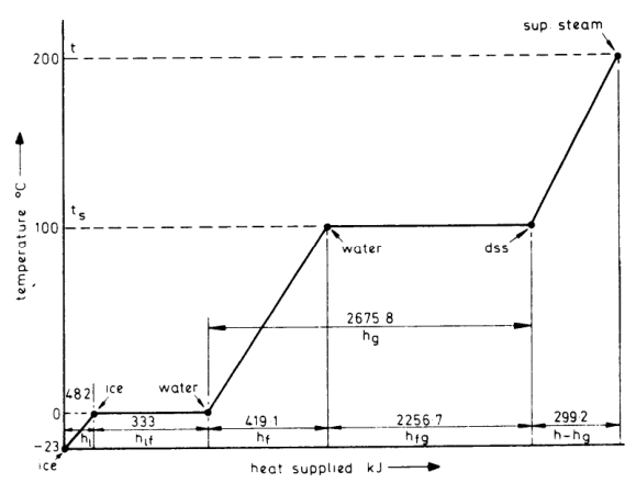
Worked through for 1 kg of ice at −23 °C raised to superheated steam at 200 °C:
| Step | Change | Heat |
|---|---|---|
| 1 | Ice −23 °C → 0 °C (sensible) | 48.2 kJ |
| 2 | Ice 0 °C → water 0 °C (latent heat of fusion) | 333 kJ |
| 3 | Water 0 °C → 100 °C (sensible, hf = 419.1 kJ) | 419.1 kJ |
| 4 | Water 100 °C → steam 100 °C (latent heat of vaporisation, hfg) | 2256.7 kJ |
| 5 | Steam 100 °C → 200 °C (superheat) | 299.2 kJ |
| 6 | Water 0 °C → dry saturated steam at 100 °C (hg) | 2675.8 kJ |
The engineer's take-away: steps 2 and 4 do the work. Step 4 — the latent heat of vaporisation — is the one the evaporator lives on, and step 2's equivalent on the condenser side is where the heat is thrown away. Latent heat is many times larger than sensible heat, which is why a refrigerant circuit moves large quantities of energy for a modest mass flow.
For a substance with constant specific heat capacity, sensible heat is Q = m · cp · (θ₂ − θ₁).
The datum for water is taken as 0 °C because that is where the state change occurs. For refrigerants the datum is often taken at −40 °C. This has no physical significance — it just avoids a mass of negative numbers.
3. Saturation Temperature — the Single Most Important Idea
The temperature at which a fluid boils or condenses is known as the saturation temperature, and it varies with pressure.
Everything else follows from this:
- Raise the pressure of a vapour → its saturation temperature rises.
- Lower the pressure of a liquid → its saturation temperature falls.
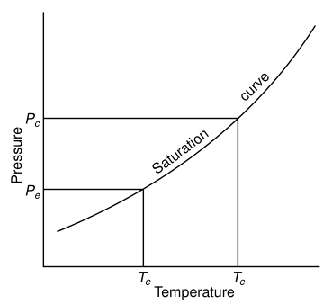
So the job of the four main components is simply to make a fluid boil at a low temperature (so it absorbs heat from the cold space) and condense at a high temperature (so it rejects heat to sea water or air):
1. Compressor
Raises the pressure of the vaporised refrigerant, so raising its saturation temperature above that of the sea water or air cooling the condenser. It also promotes circulation of the refrigerant by pumping it round the system.
2. Condenser
The refrigerant is liquefied and subcooled below the saturation temperature by the circulating sea water or air. The latent heat originally taken in at the evaporator is thus transferred to the cooling medium.
3. Expansion valve
The regulator through which refrigerant flows from the high-pressure side to the low-pressure side. The pressure drop causes the saturation temperature to fall below the actual temperature, so some liquid flashes off, taking latent heat from the remainder and cooling it. It also maintains the pressure difference between condenser and evaporator and meters refrigerant to the evaporator at the correct rate.
4. Evaporator
Refrigerant entering at a temperature lower than the secondary coolant (air or brine) receives latent heat and evaporates.
The temperature above which a gas cannot be liquefied by isothermal compression, however hard it is compressed. Every refrigerant must have its critical temperature comfortably above the normal condensing temperature. CO₂ is the classic offender: critical temperature 31 °C, so once the sea water reaches about 23 °C (31 °C less an 8 °C differential) the critical point has been reached and the efficiency of the plant steadily decreases.
4. The Vapour Compression Cycle
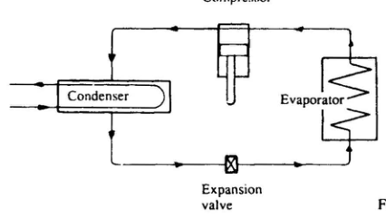
A liquid boils and condenses at a temperature which depends on its pressure. In boiling it must obtain the latent heat of evaporation; in condensing the latent heat must be given up again. The basic refrigeration cycle makes use of the boiling and condensing of a working fluid at different temperatures and therefore at different pressures.
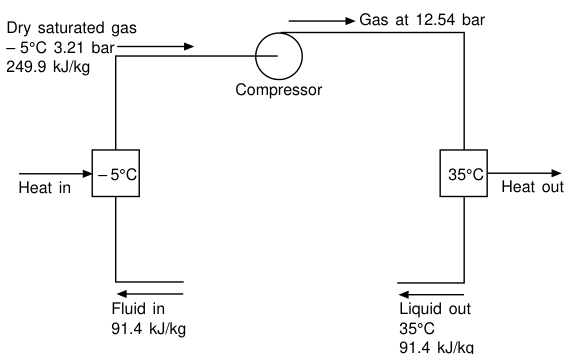
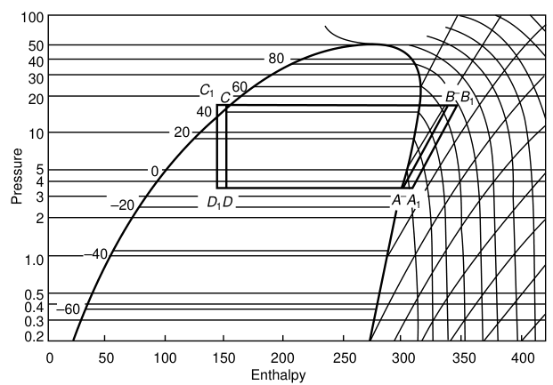
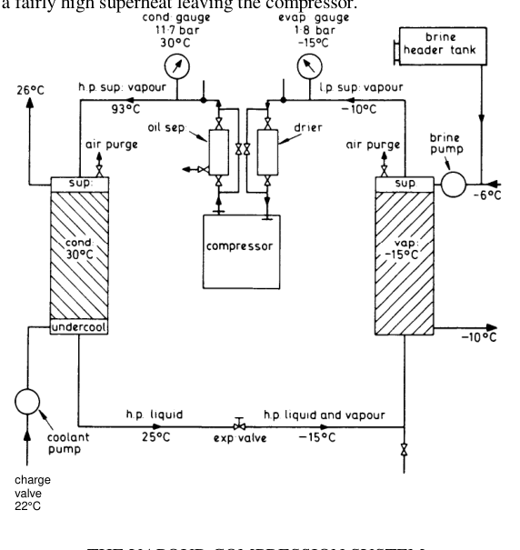
Worked example from the figure — a typical R.22 circuit:
A working system needs a connection between the condenser and the inlet to the evaporator to complete the circuit. Since these are at different pressures, this connection requires a pressure-reducing and metering valve. Because the reduction in pressure at this valve must cause a corresponding drop in temperature, some of the fluid flashes off into vapour to remove the energy for this cooling. The volume of working fluid therefore increases at the valve by this amount of flash gas — which gives rise to the name expansion valve.
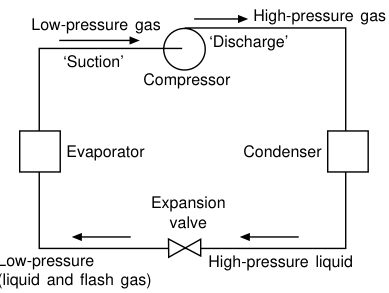
The four process steps in order, as they will be described in an oral:
Evaporation at low pressure/temperature — absorbs latent heat from the load.
Compression — raises pressure and saturation temperature.
Condensation at high pressure/temperature — rejects superheat, then latent heat, then a little subcooling, to sea water or air.
Expansion — throttles back to evaporator pressure; flash gas cools the remaining liquid.
5. Coefficient of Performance
Since the vapour compression cycle uses energy to move energy, the ratio of the two is a direct measure of performance. This ratio — the coefficient of performance (COP) — was first expressed by Sadi Carnot in 1824 for an ideal reversible cycle, based on the two temperatures of the system and assuming all heat is transferred at constant temperature.
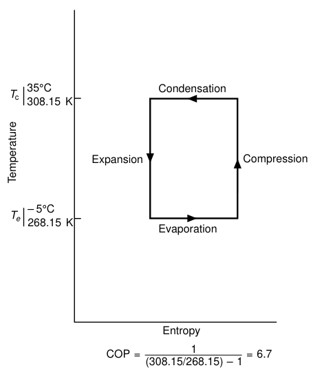
For the −5 °C / 35 °C case (268.15 K / 308.15 K):
Because there are mechanical and thermal losses in a real circuit, the actual COP is always less than the ideal Carnot figure. For practical purposes it is the ratio of the cooling effect to the input compressor power.
Transfer of heat through the walls of the evaporator and condenser requires a temperature difference. With a 5 K difference on each, the fluid operating temperatures become 263.15 K and 313.15 K and the COP falls to 5.26.
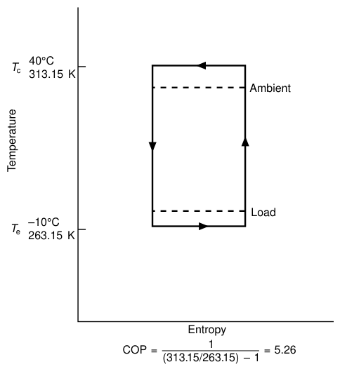
Effect of exchanger size — worth memorising
| Change | Effect 1 | Effect 2 |
|---|---|---|
| Larger evaporator | Higher suction pressure → denser gas entering the compressor → greater mass of gas for a given swept volume → higher refrigerating duty | Higher suction pressure → lower compression ratio → less power for a given duty |
| Larger condenser | Lower condensing temperature → colder liquid entering the expansion valve → more cooling effect | Lower discharge pressure → lower compression ratio → less power |
The practical COP / condensing-temperature trade (a favourite oral)
A 350 kW air-conditioning plant:
| Condensing temperature | COP | Weekly electricity cost |
|---|---|---|
| 35 °C (summer maximum) | 3.41 | 256 |
| 30 °C | 4.00 | 219 |
| 25 °C (probable minimum) | 4.73 | 184 |
This is why "run the condenser as cold as the plant will allow" is a real operating rule, not a platitude. It is also why the condenser pressure regulator should be set at the lowest pressure that gives satisfactory operation, and why a dirty condenser costs money.
6. Reading the Pressure–Enthalpy (Mollier) Chart
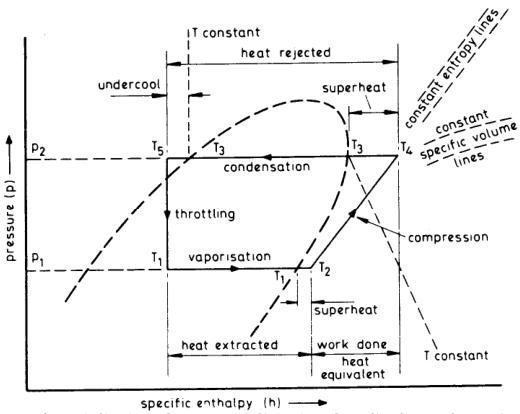
Once basic theory is established on T–s charts, the emphasis in practice shifts to the p–h (Mollier) chart, because heat extracted, heat rejected and the work-done heat equivalent can all be read off directly from the h axis in kJ/kg.
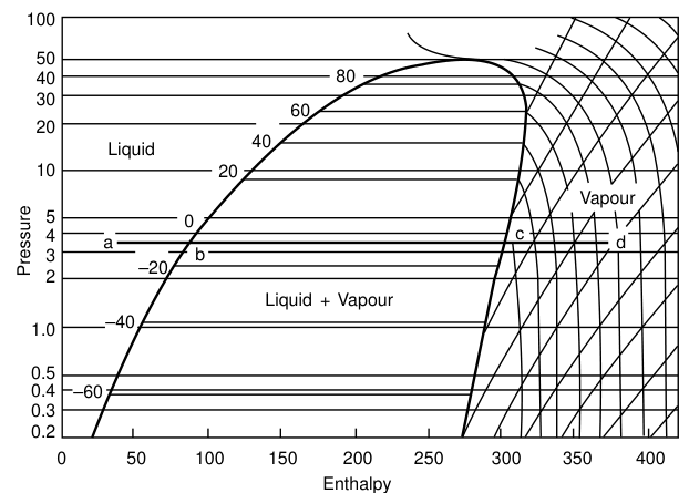
How to read the cycle:
- A→B, compression. Taken as adiabatic (isentropic) for calculation work — a vertical line. In reality it alters according to compressor type and is never perfectly vertical.
- B→C, condensation. The condenser receives high-pressure superheated gas, cools it to saturation temperature, condenses it to liquid, then subcools it slightly. The energy removed is the refrigerating effect PLUS the heat of compression.
- C→D, expansion. There is no energy input or loss within the expansion valve, so C and D lie on a line of equal enthalpy.
- D→A, evaporation. The distance D to the saturated-vapour curve indicates the proportion of flash gas at that point.
In a working circuit, the vapour leaving the evaporator will be slightly superheated (point A moves to A1) and the liquid leaving the condenser subcooled (C moves to C1). Pressure losses also occur across the gas inlet and outlet and through the heat exchangers and piping. Taking all this into account, the refrigerating effect (A1 − D1) and the compressor energy (B1 − A1) can be read off directly in kJ/kg.
Undercooling before the expansion valve reduces flash-off after the throttle, so lowering the quality and increasing the refrigerating effect in the evaporator. The practical flash-off loss is about 20 % of refrigerating effect for Freon, which does not justify the complexity of fitting two expansion valves with an intermediate liquid valve between them.
For Freon this is approximately 4.7.
7. Volumetric Efficiency
In a reciprocating compressor there is always a small clearance space at the top of the stroke, arising from gas ports, manufacturing tolerances, and an allowance for thermal expansion and contraction in operation. High-pressure gas left in this space at the end of the discharge stroke must re-expand to suction pressure before a fresh charge of gas can be drawn in.
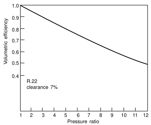
- Clearance space is usually 4–7 % of swept volume; it is possible to design compressors with less.
- The loss of useful working stroke increases with the ratio of suction to discharge absolute pressures, so compressor efficiency falls off.
- Reed's adds the practical limit: all reciprocating compressors should have the minimum reasonable piston clearance, 1.5 mm maximum, so as to give maximum efficiency.
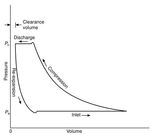
This is the reason for multistage compression and for the low-pressure cut-out setting. A high compression ratio costs volumetric efficiency and produces a high discharge temperature.
8. Multistage Cycles
Where the ratio of suction to discharge pressure is high enough to cause a serious drop in volumetric efficiency or an unacceptably high discharge temperature, vapour compression must be carried out in two or more stages. Two basic systems are used.
Compound system
Uses the same refrigerant throughout a common circuit, compressing in two or more stages. Discharge gas from the first stage is too hot to pass directly to the high-stage compressor, so it is cooled in an intercooler, using some of the available refrigerant from the condenser. The opportunity is also taken to subcool the liquid passing to the evaporator. Small compound systems may cool the interstage gas by direct injection of liquid refrigerant into the pipe.
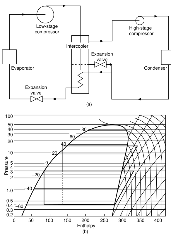
Reed's describes the same arrangement in shipboard terms: an 8-cylinder unit can operate single-stage down to −20 °C, and for temperatures below this, 6 cylinders perform the initial compression and the remaining 2 cylinders perform the final compression, with special changeover valves.
Cascade system
Two separate refrigeration systems, one acting as a condenser to the other. This permits the use of different refrigerants in the two systems; high-pressure refrigerants such as R.13 are common in the lower stage.
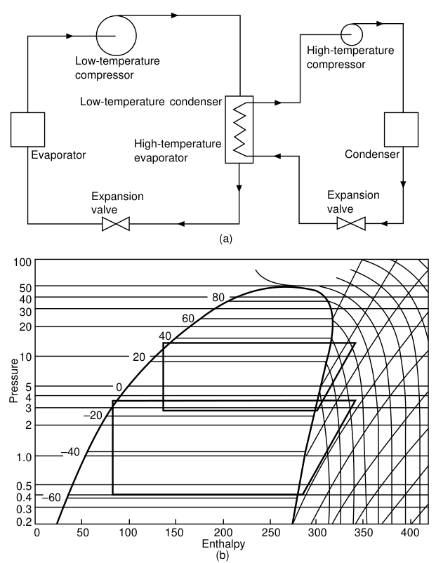
The Mollier diagrams for compound and cascade systems indicate the enthalpy change per kilogram of circulated refrigerant, but the mass flows are different for the low and high stages. Do not add them naively.
9. Alternative Cycles — Know Them, But Know They Are Alternatives
Absorption cycle
Vapour is withdrawn from an evaporator by absorption into a liquid. Two combinations are in use: ammonia gas into water, and water vapour into lithium bromide (non-toxic, so used for air conditioning — but restricted to systems above the freezing point of water).
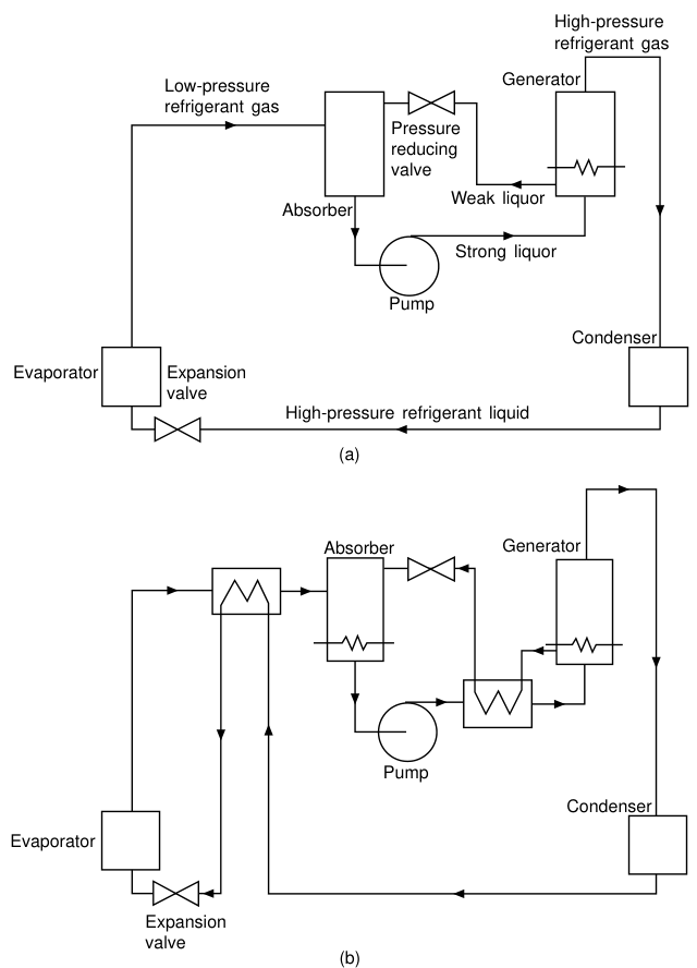
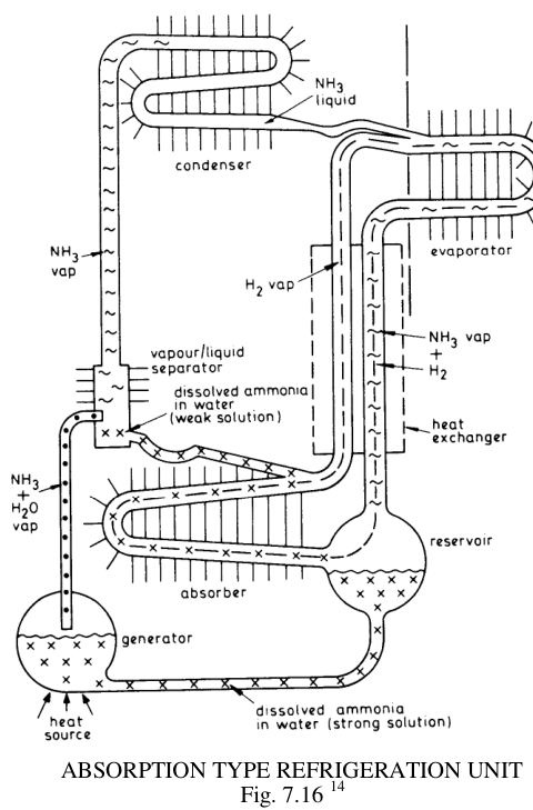
Refrigerant vapour from the evaporator is drawn into the absorber by the liquid absorbent, which is sprayed into the chamber. The resulting solution (liquor) is pumped up to condenser pressure and the vapour is driven off in the generator by direct heating. The high-pressure refrigerant gas given off is condensed in the usual way and passed back through the expansion valve into the evaporator. Weak liquor from the generator passes through another pressure-reducing valve to the absorber. Overall thermal efficiency is improved by a heat exchanger between the two liquor paths and a suction-to-liquid heat exchanger for the refrigerant. Power to the liquor pump is usually electric, but the heat to the generator may be any form of low-grade energy — oil, gas, hot water or steam (solar radiation can also be used).
The overall energy used is greater than with the compression cycle, so the COP is lower:
| Per 100 kW cooling at 3 °C evaporation, 42 °C condensation | Absorption | Vapour compression |
|---|---|---|
| Load | 100.0 | 100.0 |
| Pump / compressor (electricity) | 0.1 | 30.0 |
| Low-grade heat | 165 | — |
| Heat rejected | 265.1 | 130.0 |
The absorption system is used to advantage where there is a cheap source of low-grade heat or where there are severe limits on electrical power available.
Reed's describes the domestic absorption unit in detail — the hydrogen/ammonia/water system with no moving parts, continuous in operation when provided with a heat source such as a town gas burner or electric element. Total pressure (sum of partial pressures) is constant through the system. It requires no compressor or pump, and is silent and vibrationless. It is fairly often used in domestic units ashore but rarely on board ship, because the correct and steady level is critical for correct working.
Steam ejector system
The low pressures (8–22 mbar) required to evaporate water as a refrigerant at 4–7 °C for air-conditioning duty can be obtained with a steam ejector; high-pressure steam at 10 bar is commonly used. The COP is somewhat less than with the absorption system, so its use is restricted to applications where large volumes of steam are available when required (large, steam-driven ships) or where water is to be removed along with cooling, as in freeze-drying and fruit juice concentration.
Air cycle
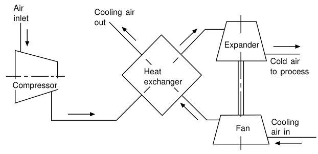
Any gas, when compressed, rises in temperature; conversely, if it is made to do work while expanding, the temperature drops. Use is made of the sensible heat only. The main application is the air-conditioning and pressurisation of aircraft. The turbines turn at very high speeds to obtain the necessary pressure ratios and are consequently noisy. The COP is lower than with other systems. The normal cycle uses the expansion of the air to drive the first stage of compression, so reclaiming some of the input energy.
Thermoelectric (Peltier) cooling
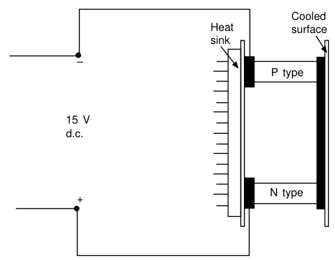
Passage of an electric current through junctions of dissimilar metals causes a fall in temperature at one junction and a rise at the other — the Peltier effect. Improvements have been made possible by suitable semiconductors. Applications are limited in size owing to the high electric currents required; practical uses are small cooling systems for military, aerospace and laboratory use.
Total-loss refrigerants
Some volatile fluids are used once only and then escape to atmosphere. Two are in general use:
- Carbon dioxide — stored as liquid under pressure and low temperature, released when cooling is required. Below its critical point at atmospheric pressure, so it can only exist as "snow" or a gas. Released at −78.4 °C.
- Nitrogen — released at −198.8 °C.
- Water ice can also be classified as a total-loss refrigerant.
Since both gases come from the atmosphere, there is no pollution hazard.
10. Requirements for a Working Fluid
Ten requirements for a refrigerant in a vapour compression cycle:
A high latent heat of vaporisation
High density of suction gas
Non-corrosive, non-toxic and non-flammable
Critical temperature and triple point outside the working range
Compatibility with materials of construction, with lubricating oils, and with other materials present in the system
Convenient working pressures — not too high, and preferably not below atmospheric
High dielectric strength (for compressors having integral electric motors)
Low cost
Ease of leak detection
Environmentally friendly
No single working fluid has all these properties. The present situation has been dominated by the need for environmentally friendly fluids.